Page is loading ...

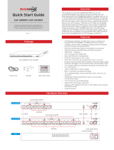
Package
ITS-100 Quick Start Guide
Hardware Overview
Right
Left
Error
Watt
Volt
Ohm
UnitDisplay
ECP
Termination Mode
Bypass Mode
ETPEUP
PoE IN PoE Out
Bypass Mode
Termination Mode
Overview
This product is a device used to check the power consumption
available at the place where a camera is installed. The ITS-100
measures and displays the cable resistance from the receiver
to the location of the tester, and the power consumption of the
transmitter that can be used there.
As the tester can check the power supply and the cable status
where the camera is placed, it is also possible to use the ITS-100 for
installation and maintenance.
Features
■ Termination Mode
(B-Linx Termination Mode, ECP/EUP/ETP products)
Provides information about the cables used where the camera
will be installed.
Shows the power consumption (Watt) available for the measured
cable (Review of the PoE cameras that can be installed is possible).
Cable resistance (Ohm) from the receiver (Rx) to the tester.
Voltage supplied from the receiver (Rx) to the tester (The tester
measures overvoltage and undervoltage, not the supply voltage).
Shows an Error when an operation failure is likely to happen on a
PoE product (based on the cable voltage drop).
Shows the measurement information (periodic measure, shown
on the Display window).
ÎThe tester does not work if it is not connected to a receiver (Rx).
The tester does not have a battery, and operates with the output
voltage of the receiver (Rx).
■ Bypass Mode (cable connection mode, PoE)
The tester is set in the middle of the PoE cable and measures the
cable performance while the camera is in operation.
Measures the power consumption (Watt) while the camera is in
operation.
Measures the cable voltage (Volt) while the camera is in operation.
Measures the power consumption of the camera when the tester
is installed on the camera side.
Shows real-time measurements (periodic measure, shown on the
Display window).
Operates when a PoE camera (PD device) is connected to the PoE
Output terminal.
ÎThe tester might not work if it is not used with a PD device. (The
tester does not have a battery, and operates with the output
voltage from the PSE).
Rev.2.0
Specifications
Termination Mode Bypass Mode (PoE) Remarks
Operating
Voltage
(VDC)
12~60V 38~60V
Bypass Mode is limited to
the PoE operating range
(af/at)
Display
FND 2 digits, Red 2 digits, Red 7-segment display, 2
digits
LED
Red: Error
Yellow: Wattage (W)
Green: Voltage (V)
Orange: Resistance
(Ω)
Red: Error
Yellow: Wattage (W)
Green: Voltage (V)
Orange: Resistance
(Ω)
The LED shows the unit
corresponding to the FND
value displayed.
Error: If the tester is
out of the operating
range, the LEDs for the
measurement units
will flash in sequence
repeatedly.
Display
range
PoE Budget: 1-99W
Voltage: 38-58V
Resistance: 1-200 Ω
Error: 2 digits
PoE Budget: 1-60W
Voltage: 38-58V
Resistance: 1-200 Ω
Error: 2 digits
Input
terminal
ECP: BNC
EUP: RJ45 (red)
ETP: 2P Terminal model
PoE IN: RJ45 (metal)
PoE model
Output
terminal None
PoE OUT: RJ45
(metal) connection to
PoE camera
Repetition
of the
Measurement
5s interval 3~5s interval Information displayed
sequentially
Detection
function
No Smart detection
No PD function
None
The PSE recognizes
the connected PD
camera
The bypass Mode bypasses
the PoE signal to the
output, so it only measures
power, not speed
Measurement Display
The measurement value and the unit of measurement appear
sequentially (Integer only).
While the measure is being calculated, a small dot LED will be “On”
at the bottom of the FND.
Measurements above 100 will be displayed in two times (the first
time shows the hundreds, the second time shows digits from
00~99. The unit LED stays on while the measure is displayed).
Voltage (ex.: 38V display) Resistance (ex.: 123 Ohm display)
"38" + "Volt LED" "01" + "23" + "Ohm LED"
Error
Watt
Volt
Ohm
Error
Watt
Volt
Ohm
Error
Watt
Volt
Ohm
Error
Watt
Volt
Ohm
Error
Watt
Volt
Ohm
Fault Indication
There will be an error message if the measure is out of the
product specification range.
Error display: Display (FND) + Error LED + Unit LED
Failure Display LED
Over Load (99W and over) Ou +
Low voltage (38V and under) Lo +
Over voltage (58V and over) Ou +
Over current (1.2A and over) Oc +
Quick Start Guide
ITS-100
Cable & Power Budget Tester
Please read carefully the instruction manual before use.
Contents of this manual are subject to change without prior
notice for reasons such as functionality enhancements.

Installation Guide
ÎDo not use the Termination Mode and Bypass Mode at the same
time. The measurements will not be accurate.
■ Termination Mode
The termination mode is used to check the cable status where the
camera and transmitter (Tx) are connected. The measurement is
possible when connected to an Intercoax ECP, ETP, EUP product
while in normal operation.
1. Connect the ITS-100 to the transmitter (Tx) using the correct
terminal.
ÎDo not connect ECP, ETC and EUP terminals at the same time.
Connect and measure one by one.
Error
Watt
Volt
Ohm
Error
Watt
Volt
Ohm
Power Supply
ITS-100
Tx / 카메라 설치 장소
ITS-100
ITS-100
ECP/EUP/ETP
Receiver
PoE Camera
PoE Camera
ⓐ ⓑ
ⓐ ⓑ
PoE IN
EUP ETP ECP
PoE OUT
PoE IN PoE OUT
PoE
Switch
PoE
Switch
Tx / Camera location
2. Once the ITS-100 is connected and running, the measurement
will appear.
3. Categories
Type of
measurement Content Unit LED
Power
available at
installation
place
Shows the standard voltage range of the PoE product
when operating normally. The value for the “Available
Power Consumption” where the tester (ITS-100)
is installed must be greater than the total power
consumption of the transmitter (Tx) and the camera
to avoid problems when installing the product
Watt
Voltage at
Installation
place
Shows the Voltage where the tester is installed
Shows the Voltage drop when the tester (ITS-100) is
on “Load”, not the Voltage at the Rx output, nor the
voltage at the maximum load
Volt
Cable
Resistance
Shows the cable resistance, measures from the
receiver (Rx) to the tester (ITS-100) Ohm
■ Bypass Mode
It is used to check the cable connection to a PoE camera (PoE
product). The measurement is possible when PoE equipment
(product with PSE function such as a PoE switch for example) is
connected to a PoE camera and operating normally.
Do not connect products from the EUP series in this
mode, as it may cause damages to the device.
1. Connection
[CASE 1]: The ITS-100 tester is connected at the end of
the LAN cable, on the side of the PoE (PD) camera
ⓐ Connect the long-distance LAN cable to the ITS-100 Tester’s
PoE IN where the camera will be installed.
ⓑ Connect the PoE camera to the ITS-100 Tester’s PoE OUT.
Error
Watt
Volt
Ohm
Error
Watt
Volt
Ohm
Power Supply
ITS-100
Tx / 카메라 설치 장소
ITS-100
ITS-100
ECP/EUP/ETP
Receiver
PoE Camera
PoE Camera
ⓐ ⓑ
ⓐ ⓑ
PoE IN
EUP ETP ECP
PoE OUT
PoE IN PoE OUT
PoE
Switch
PoE
Switch
[CASE 2]: The ITS-100 tester is connected to the PoE [PSE]
ⓐ Connect the PSE product or the output terminal of the PoE
switch to the ITS-100 Tester’s PoE IN.
ⓑ Connect the long-distance LAN cable to the ITS-100 Tester’s
PoE OUT, then connect the PoE camera at the end of the cable.
Error
Watt
Volt
Ohm
Error
Watt
Volt
Ohm
Power Supply
ITS-100
Tx / 카메라 설치 장소
ITS-100
ITS-100
ECP/EUP/ETP
Receiver
PoE Camera
PoE Camera
ⓐ ⓑ
ⓐ ⓑ
PoE IN
EUP ETP ECP
PoE OUT
PoE IN PoE OUT
PoE
Switch
PoE
Switch
2. Once the ITS-100 tester is connected, wait a few moments
before the measurement appears.
3. Categories
Type of
Measurement Content Unit LED
Power
consumption
while in
operation
CASE 1: Shows the power consumption of the
camera (cable loss value not included).
CASE 2: Shows the cable specifications and total
power consumption, including the camera.
Watt
Voltage at
installation
place
Measures the voltage where the ITS-100 tester is
installed.
CASE 1: Shows the cable’s voltage drop when the
PoE camera is in operation.
CASE 2: Shows the output voltage of the PSE or the
PoE Switch.
Volt
Cable
resistance
Measures the cable resistance from the PSE or PoE
switch to the ITS-100 tester. If the LAN cable is
removed from the PoE OUT while the ITS-100 tester
is in operation, the resistance of the cable connected
to the PoE IN will be displayed (The resistance of the
cable connected to the PoE OUT is not measured).
Ohm
Display
Information
If the camera LAN cable is connected to the PoE OUT,
the display voltage drop and power consumption
supplied to the camera is displayed. If the camera
LAN cable is disconnected from the PoE OUT, the
PoE Output voltage and the cable resistance up to
the ITS-100 Tester’s PoE IN are displayed.
- -
Remarks
Because of the cable voltage drop, the measurement in wattage/
voltage decreases compared to the power supplied to the cable
by the receiver (Rx).
This product is not a precision measuring device. The measurements
have a tolerance and are not guaranteed values.
The tester should be used during short periods of time, especially
when using the Termination Mode. The possibility of measurement
differences is greater if the tester is connected for a long time in
Termination Mode, because of heat generation.
Caution
Make sure to follow the instructions of the user manual when
installing and using the device.
Do not use the product for projects requiring guaranteed
measurements as this is not a precision measuring device.
Do not use the product for long periods of time.
Do not touch or handle the product and cables with wet hands,
as there are risks of electrocution.
Keep away from moisture and shocks.
This product is designed for indoor use. Do no use outdoors.
Do not use the product for any other purpose than that for which
it is designed.
Do not disassemble or modify this device.
Do not put any sticker or paint on the device.
If the device shows signs of defects or malfunctions, contact the
dealer where your purchased it or the service center.
Warranty
This device has passed the quality control and product inspection.
Please install and use according to the installation guide.
The warranty period for this product is 24 months from the date
of purchase.
If this device is defective or malfunctioning, please unplug the
power adapter immediately and contact dealer or service center.
Any damages or breakage from user’s abuse, accident,
modification or natural disasters will not be covered
manufacturer’s warranty.
Please visit below website for more detailed information.
Web: http://www.intercoax.com Tel: +82. 31. 365. 3133~4
E-mail: [email protected] Fax: +82. 31. 365. 3135
This device complies with part 15 of the fcc rules. Operation is subject to the
following two conditions :
(1) This device may not cause harmful interference, and
(2) This device must accept any interference received including interference
that may cause undesired operation
© Intercoax Co., Ltd.
/