Page is loading ...

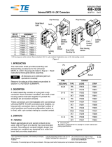
Through-Hole
Contacts
Locking
Tab Locking
Latch
Panel Stop
(4 Places)
Mounting Ear
(2 Places)
Vertical
Pin Header
(770875-1)
Right Angle
Pin Header
(770969-1, Ref)
Plug Housing
(172339-1, Ref) Cap Housing
(172331-1, Ref)
© 2012 Tyco Electronics Corporation, a TE Connectivity Ltd. company
All Rights Reserved
*Trademark
TE Connectivity, TE connectivity (logo), and TE (logo) are trademarks. Other logos, product and/or Company names may be trademarks of their respective owners.
1 of 3
Instruction Sheet
TOOLING ASSISTANCE CENTER
1-800-722-1111
PRODUCT INFORMATION
1-800-522-6752
This controlled document is subject to change.
For latest revision and Regional Customer Service,
visit our website at www.te.com
408-3234
Mini-Universal MATE-N-LOK*
Connectors 24 FEB 12 Rev F
Figure 1
1. INTRODUCTION
Mini-Universal MATE-N-LOK connectors, shown in
Figure 1, are available in plug housings and cap
housings for wire-to-wire free-hanging and panel
mount applications, and vertical pin headers and right-
angle pin headers for wire-to-printed circuit (pc) board
applications.
NOTE
i
A complete list of current connector and contact
part numbers cannot be maintained in this
document. For all part numbers and their
description, refer to the applicable catalog, or call
PRODUCT INFO at the number at the bottom of
this page.
NOTE
i
Dimensions in this instruction sheet are in
millimeters [with inches in brackets]. Figures are
not drawn to scale.
Read these instructions, and those referenced, before
assembling or disassembling the connectors.
Reasons for reissue of this instruction sheet are
provided in Section 6, REVISION SUMMARY.
2. DESCRIPTION
The housings accept pin or socket contacts crimped
onto stranded wire, and the pin headers contain
through hole contacts for soldering onto the pc board.
The connectors (except the hermaphroditic) are
polarized for proper mating. Keying plugs are available
for the connectors to provide additional polarization for
mating. The positive locking mechanisms (locking
latch and locking tab) prevent accidental
disengagement of mated connectors.
The cap housing features mounting ears and panel
stops to aid in mounting to a panel.
3. ASSEMBLY
NOTE
i
For specific application and inspection
requirements, refer to Application Specification
114-16017.
3.1. Housings
A. Selection and Preparation
1. Select the appropriate contact according to the
wire size and insulation diameter to be used. Refer
to Figure 2.
Pin Socket
WIRE CONTACT † (Loose Piece) ‡
SIZE (AWG)
RANGE INSUL DIA
RANGE PIN SOCKET
30 - 26 0.89 - 1.27
[.035 - .050] 794059-[ ] 794058-[ ]
26 - 22 1.19 - 1.75
[.047 - .069] 770985-[ ] 770986-[ ]
22 - 18 or
22 (2 Wires) 1.49 - 2.79
[.059 - .110] or
3.38 [.133] Max 770987-[ ] 770988-[ ]
20 - 16 or
20 (2 Wires) 2.00 - 3.20
[.079 - .126] or
4.78 [.188] Max 171638-[ ] 171639-[ ]
† Contact part numbers listed are not intended to be a complete
list. Refer to the applicable catalog.
‡ If using strip form contacts, make sure that the cutoff tab length
conforms to the requirements in 114-16017.
Figure 2

408-3234
2 of 3
Rev F
2. Strip the wire 3.20 to 3.71 [.126 to .146] for one-
wire application and 3.50 to 3.99 [.138 to .157] for
two-wire application. Reasonable care must be
taken not to nick, scrape, or cut any strands during
stripping.
3. Crimp the contact using the appropriate hand tool
(for loose piece contacts) or machine (for strip form
contacts). Refer to the instructions packaged with
the tool or machine for crimping procedures.
NOTE
i
For available tooling, refer to 114-16017. Consult
your local representative for assistance in selecting
the tool or machine that will best suit your needs.
B. Contact Insertion and Removal
Insert the contacts into the housing according to the
following:
1. Align the contact with the desired contact cavity
at the BACK (wire side) of the housing.
2. Grasp the wire-directly behind the contact
insulation barrel-and push the contact straight into
the cavity until it bottoms (there should be an
audible click). Pull back lightly on the wire to be sure
the contact is locked in place. See Figure 3.
Contact Insulation Barrel
Contact Cavity
Back (Wire Side)
of Housing
Figure 3
NOTE
i
Insertion Tool 455830-1 is available for inserting
contacts crimped onto small wire sizes or when the
wire bundle is too large for hand insertion. For
information on using the tool, refer to 408-7984.
3. If removal is necessary, use Extraction Tool
189727-1 to remove the contact from the housing.
For information on using the tool, refer to 408-4118.
C. Keying Plug Insertion and Removal
Determine the applicable contact cavity to be keyed,
and make sure that the cavity is empty. Then install
the keying plug according to the following.
NOTE
i
Corresponding cavities in the pin header or cap
housing must be empty.
1. Align the tapered end of the keying plug with the
desired contact cavity at the FRONT (mating face)
of the housing. Insert the keying plug straight into
the cavity until it snaps into position. Refer to
Figure 4.
Front (Mating Face)
of Housing
Empty Contact
Cavity
Tapered End
of Keying Plug
Keying Plug
(174670-1, Ref)
Figure 4
2. If removal is necessary, grip the keying plug
with pliers at the FRONT of the housing, and pull
straight out.
D. Panel Mounting (Cap Housing Only)
1. Design the panel using the dimensions
provided on the customer drawing for the
specific cap housing.
2. Insert the cap housing (mating face first) through
the panel cutout in the same direction as the punch.
Make sure that the panel stops are flush with the
panel, and the mounting ears are against the panel.
Refer to Figure 5.
3. If removal is necessary, deflect the mounting ears
until they clear the panel, then pull the cap housing
through either the front or back of the panel.
Panel Stops Flush
with Panel
Mounting Ears
Against Panel
Figure 5

408-3234
3 of 3
Rev F
3.2. Pin Headers
1. Design the pc board using the dimensions
provided on the customer drawing for the specific
pin header.
2. Solder the pin header to the pc board according
to Application Specification 114-16017.
3. If removal is necessary, use standard de-
soldering methods.
3.3. Mating Connectors
NOTE
i
Check to be sure mating connectors have identical
number of circuit positions.
1. Align the mating faces of the connectors.
NOTE
i
The end contact cavities of the cap housing are
marked with the circuit position, and along the side
of the plug housing is a raised alignment rib
indicating Position 1.
2. Insert the plug housing straight into the mating
connector until it bottoms and the locking latch
engages and is fully seated on the locking tab of the
mating connector. Refer to Figure 6.
Locking Tab and Locking
Latch Engaged
Cable Tie
(Ref)
76.2 [3.00] Min
Distance
Free Hanging Application Shown
Requirements Apply Equally to PC Board Applications
Figure 6
3. If necessary, bundle wires together and support
with cable ties or similar device. Make sure that the
distance of the cable tie from the wire end of the
connector is a minimum of 76.2 [3.0]. Refer to
Figure 6. Keep the wires perpendicular to the
connectors and avoid an excessively sharp bend
radius. DO NOT stretch or confine the wires in
any way.
4. DISASSEMBLY
To disengage mating connectors, release the locking
latch of the plug housing from the locking tab of the
mating connector, and pull the connectors apart.
CAUTION
!
DO NOT pull the connectors by the wires.
5. REPLACEMENT AND REPAIR
The contacts and connectors are not repairable.
Discard and replace any defective or damaged
contacts or connectors. DO NOT re-use a terminated
contact by removing the wire.
DO NOT re-use pin headers after removal from the pc
board.
6. REVISION SUMMARY
Since the previous version of this document, the
following changes were made:
•Updated document to corporate requirements.
/


