Page is loading ...

M-Series Meters
M-5®, M-7®, M-10®, M-15®, M-25®, M-30®, M-40®, M-60®, M-80®
MA®-Series Meters
MA-4®, MA-5®, MA-7®, MA-15®
Installation
Manual
& Setup Guide
M-Series Meters
MA®-Series Meters
LC_IOM_M/MA Meters 09202021

2 WWW.LCMETER.COM
Be Prepared
TABLE OF CONTENTS
INTRODUCTION
Safety Procedures ................................................... 3
Owner’s Information Packet ..................................... 4
Serial Number Plate Locations ................................ 5
How LC Meters Work............................................... 6
INSTALLATION & OPERATION
Installation Requirements ........................................ 7
Operation Requirements.......................................... 8
Meter Start Up and Operation .................................. 9
Reversing the Meter Registration ........................... 10
Setting the Standard Adjuster ................................. 11
MAINTENANCE
Maintenance Requirements .................................... 12
Relieving Internal Pressure ..................................... 13
Servicing the Drive Components ............................. 13
Removing the Dust Cover ............................................. 13
Removing the Adjuster and Adjuster Drive Assembly ..... 14
Servicing the Packing Gland ......................................... 15
Packing Gland Retaining Plate ...................................... 15
Disassembling the Meter ......................................... 16
Removing Non-Corroded Rotor Gears .......................... 17
Removing Corroded Rotor Gears .................................. 17
Reassembling the Meter ......................................... 18
Timing the Rotor Gears ................................................. 19
Torque Chart ................................................................ 21
Wrench and Socket Size Chart ..................................... 21
Troubleshooting ...................................................... 22
How to Order Replacement Parts ........................... 23
BILL OF MATERIALS
Bill of Materials ........................................................ 24
!
WARNING
•
Before using this product, read and understand the instructions.
•
All work must be performed by qualified personnel trained in the proper application, installation, and
maintenance of equipment and/or systems in accordance with all applicable codes and ordinances.
•
When handling electronic components and boards, always use proper Electrostatic Discharge (ESD)
equipment and follow the proper procedures
•
Make sure that all necessary safety precautions have been taken.
•
Provide for proper ventilation, temperature control, fire prevention, evacuation, and fire management.
•
Provide easy access to the appropriate fire extinguishers for your product.
•
Consult with your local fire department, state, and local codes to ensure adequate preparation.
•
Read this manual as well as all the literature provided in your owner’s packet.
•
Save these instructions for future reference.
•
Failure to follow the instructions set forth in this publication could result in property damage, personal injury,
or death from fire and/or explosion, or other hazards that may be associated with this type of equipment.
Publication Updates and Translations
The most current English versions of all Liquid Controls publications are available on our web site, www.lcmeter.com. It is the
responsibility of the local distributor to provide the most current version of LC manuals, instructions, and specification sheets in
the required language of the country, or the language of the end user to which the products are shipping. If there are questions
about the language of any LC manuals, instructions, or specification sheets, please contact your local distributor.

WWW.LCMETER.COM 3
Safely Evacuate
Piping System
NOTICE
This manual provides warnings and procedures that are intended to inform the owner
and/or operator of the hazards present when using the Liquid Controls Meter on LP-
Gas and other products. The reading of these warnings and the avoidance of such
hazards is strictly in the hands of the owner-operators of the equipment. Neglect of
that responsibility is not within the control of the manufacturer of the meter.
SAFETY PROCEDURES
!
WARNING
Before disassembly of any meter or accessory component:
• All internal pressures must be relieved and all liquid drained from the system in
accordance with all applicable procedures.
• Pressure must be 0 (zero) psi.
• Close all liquid and vapor lines between the meter and liquid source.
For Safety Rules, refer to local authorities and relevant NFPA Codes.
Failure to follow this warning could result in property damage, personal injury, or death from
e and/or explosion, or other hazards that may be associated with this type of equipment.
In the Event of
a Gas Fire
!
IN THE EVENT OF LARGE FIRES OR FIRES THAT ARE SPREADING
■
Evacuate the building and notify your local fire department.
■
Stop the leakage only if you can safely reach the equipment.
IN THE EVENT OF SMALL, CONTAINED FIRES THAT YOU CAN SAFELY
CONTROL
■
Stop the leakage if you can safely reach the equipment.
■
Use the appropriate extinguisher: Class B fire extinguisher, water, fog, etc.,
depending on the materials.
■
If in doubt, call your local fire department.
In the Event of
a Gas Leak
!
IN THE EVENT OF A LARGE GAS LEAK
■
Evacuate the area and notify the fire department.
IN THE EVENT OF A SMALL, CONTAINED GAS LEAK
■
Stop the leak and prevent accidental ignition.
■
Prevent the entrance of gas into other portions of the buildings. Some gases, such
as LPG, seek lower levels, while other gases seek higher levels.
■
Evacuate all people from the danger zone.
■
See that the gas is dispersed before resuming business and operating motors.
If in doubt, notify your local fire department.

4 WWW.LCMETER.COM
OWNER’S INFORMATION PACKET
Inquires, Orders, and Service
Please have the following information available when you make inquires, order replacement parts, or schedule
service. If a specific meter accessory is involved, please provide the model and serial number of the accessory in
question.
Your Meter’s Serial Number:
Your Full-Service Distributor:
Your Full-Service Distributor’s Telephone Number:
Owner’s Information Packet
1.
CHECK YOUR OWNER’S INFORMATION PACKET
LC meters come in many variations. The information sent to you depends on the accessories you have ordered
with your meter. Make an inventory of your red Owner’s Information Packet. First, find your LC packing slip with
the computer printout. Locate the serial number and the meter model number on this printout. Cross reference
the packing slip number with the actual meter numbers. The illustration on following page will help you locate the
Specification and Serial Number Plates on the meter and its accessories.
2.
RECORD YOUR METER SERIAL NUMBER
Record your meter serial number and your full-service distributor’s name and telephone number in the space
provided above. Save this information and keep it handy. When calling for service or parts, you will need to
supply your meter serial number and model number. See How to Order Replacement Parts on page 23 for more
information.
3.
IDENTIFY YOUR METER’S MODEL-ACCESSORY LETTER.
Use the diagrams below to familiarize yourself with meter accessories. Find the meter and letter on the diagram
which represents your meter system, then check with the chart below to see that your red owner’s information
packet is complete. Not all accessory levels are available for every model of LC meter.
4.
MAKE SURE ALL DOCUMENTATION IS INCLUDED WITH YOUR METER
Check your red Owner’s Information Packet against the diagrams below to make sure that all the documentation
needed for your meter and accessories is included in your packet. If documentation is missing, contact your
full-service distributor or Liquid Controls or visit www.lcmeter.com where you can find the most up-to-date LC
literature.


6 WWW.LCMETER.COM
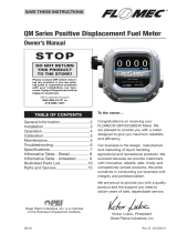
HOW LC METERS WORK
Liquid Controls meters are positive displacement
meters. They are designed for liquid measurement in
both custody transfer and process control applications.
They can be installed in pump or gravity flow systems.
Because of their simple design, they are easy to
maintain, and easy to adapt to a variety of systems.
The meter housing (1) is designed with three cylindrical
bores (2). Three rotors, the blocking rotor (3) and
two displacement rotors (4, 5), turn in synchronized
relationship within the bores. The three rotors are
supported by bearing plates (6, 7). The ends of the
rotors protrude through the bearing plates. The blocking
rotor gear (8) is placed on the end of the blocking
rotor. The displacement rotor gears (9, 10) are placed
on the ends of the displacement rotors. These gears
create the synchronized timed relationship between the
three rotors.
As fluid moves through the meter housing, the rotor
assembly turns. The liquid is broken into uniform
sections by the turning rotors. Fluid displacement occurs
simultaneously. As fluid enters, another portion of the
fluid is being partitioned and measured. At the same
time, the fluid ahead of it is displaced out of the meter
and into the discharge line. Since the volume of the
bores is known, and the same amount of fluid passes
through the meter during each revolution of the blocking
rotor, the exact volume of liquid that has passed through
the meter can be determined with a high degree of
accuracy.
This true rotary motion is transmitted through the
packing gland, the face gear, the adjuster drive shaft,
and the adjuster to the register stack and counter. True
rotary motion output means consistent accuracy since
the register indication is in precise agreement with the
actual volume throughput at any given instant.
At any position in the cycle, the meter body, the blocking
rotor, and at least one of the displacement rotors form
a continuous capillary seal between the unmetered
upstream product and the metered downstream product.
Because the product is separated by the capillary seal,
Meter Element Exploded Line Drawing
no metal-to-metal contact is required within the metering
element. This means no wear. No wear means no
increase in slippage, and no increase in slippage means
no deterioration in accuracy.
Throughout the metering element, the mating surfaces
are either flat surfaces or cylindrical faces and sections
that are accurately machined. These relatively simple
machining operations, plus the fact that there is no
oscillating or reciprocating motion within the device,
permits extremely close and consistent tolerances within
the LC meter.
The product flowing through the meter exerts a
dynamic force that is at right angles to the faces of the
displacement rotors. The meter is designed so that the
rotor shafts are always in a horizontal plane. These two
facts result in no axial thrust; therefore, LC meters do
not need thrust washers or thrust bearings, the rotors
automatically seek the center of the stream between the
two bearing plates, eliminating wear between the ends of
the rotors and the bearing plates. Once again, no wear
results in no metal fatigue and no friction.
Liquid Controls meters are made of a variety of materials
to suit a variety of products. Because of their no-wear
design, capillary seals, and unique rotary metering, LC
meters provide unequalled accuracy, long operating life,
and unusual dependability.

WWW.LCMETER.COM 7
Under normal operation, do not expose any portion
of the LP-Gas system to pressures in excess of rated
working pressures without an automatic safety valve to
vent the over pressure discharge to a place of safety
away from the operator and other people.
Failure to provide such a safety relief
may result in leakage or rupture of one or
more of the components in the system.
This can result in injury of death from the
e, or pieces of bris from
the rupture.
!
WARNING
Class 10 LPG Meters - Codes
Class 10 LPG meters must be installed in accordance with the
requirements of ANSI-NFPA 58 in addition to all other state and
local codes.
▪
TAKE ALL NECESSARY SAFETY PRECAUTIONS
Make sure that all necessary safety precautions have been taken.
Provide for proper ventilation, temperature control, fire prevention,
evacuation and fire management.
▪
PROVIDE ACCESS FOR FIRE EXTINGUISHERS
Provide easy access to the appropriate fire extinguishers for your
product. Consult with your local fire department and state and local
codes to make sure that you are adequately prepared.
▪
READ PROVIDED LITERATURE
Read this manual as well as all the literature provided in your red
Owner’s Information Packet. If you have any questions, consult
with your full-service distributor or call the Service Department at
Liquid Controls.
▪
CONFORM TO ALL CODES
Install the meter and accessories in conformance with applicable
state and federal construction, electrical and safety codes.
▪
LEAVE THREAD CAPS IN PLACE
Before shipment, protective thread caps are placed in all meter
and accessory openings. They should remain in place until you
are ready to attach piping.
▪
FLUSH PIPING
Prior to meter installation, the entire piping system should be
thoroughly flushed of all debris with a liquid that is compatible with
the construction of the meter.
▪
KEEP EXTERNAL SURFACES OF THE METER
CLEAN
▪
MOUNT METER SECURELY
The meter must always be securely bolted to a platform or
supporting member, regardless of the mounting position of the
meter. Never “hang” a meter on the connecting piping.
▪
PREVENT PIPE STRAIN OR STRESS
Prevent pipe strain or stress from occurring when making meter or
accessory repairs. Pipe strain and stress occurs when the pipes
are not supported or are not aligned correctly to the meter. The
weight of the pipes must always be supported independent of the
meter. This means that the meter and accessories can be easily
removed without affecting the pipes or the pipe alignment. Never
leave any of the pipes hanging.
▪
INSTALL METER ONLY ON THE DISCHARGE
SIDE (DOWNSTREAM) OF THE SYSTEM PUMP
▪
APPLY PIPE COMPOUND TO MALE THREADS
ONLY
▪
LEAVE SPACE FOR FUTURE MAINTENANCE
Position the meter with service in mind. Provide ample work
space. Removing covers can be difficult when work space is
not available. Always supply a platform or support for the meter
mounting.
▪
USE METER ONLY WITH SPECIFIED LIQUIDS
A meter is metallurgically designed to be physically compatible
with the type of liquid originally specified by the customer, and
as indicated on the Serial Number Plate. A meter should not be
used with a liquid different from the liquid originally specified,
unless the physical characteristics and pH rating are similar and
the application has been checked with LC Sales and Engineering
through your full-service distributor.
INSTALLATION REQUIREMENTS
▪
INSTALL A STRAINER
Install a strainer on the meter inlet to avoid damage from foreign
matter, such as weld slag, from entering the system. The strainer
must always be located on the inlet side.
▪
TAG FLOW DIRECTION
All meters are tagged identifying their direction of flow. Meters
are set with a flow direction of left to right as standard. However,
when a meter is ordered, the customer can specify that the flow
be set from either direction. If the meter register counts in reverse,
the meter is reading the direction of flow in reverse. If this occurs,
the meter registration must be reset. For mechanical output
meters, see Reversing the Meter Registration on page 10. For
electrical output meters, such as meters equipped with a pulser
or an electronic register, refer to the manual of the electronic
component.
▪
USE CURRENT ENGINEERING DRAWINGS
Always request up-to-date, engineering approved, dimensional
drawings before starting any construction. Do not rely on catalog
pictures or drawings. They are for reference only. After receiving
prints, check to see that all equipment ordered is shown and
that any extra pressure taps, plugs, etc. are noted and their size
specified.

8 WWW.LCMETER.COM
OPERATION REQUIREMENTS
▪
THE METER MUST REMAIN FULL OF PRODUCT
AT ALL TIMES.
An easy way to accomplish this is to put the meter assembly in the
line below the piping center-line (a sumped position). This requires
adding elbows and flanges prior to installing the meter. The meter
should be installed in a bypass loop, below the pipe center-line,
with block valves upstream and downstream of the meter inside
the bypass loop. A block valve should be located in the main
pipeline and labeled as the bypass valve.
▪
PIPING PRESSURE RELIEF
Any portion of pipe system that might isolate or block flow should
be provided with a pressure relief to prevent damage from thermal
expansion. There are excellent benefits to this type of installation.
First, the meter is kept full. Second, this type of installation
allows the meter to be isolated for servicing and calibration while
continuing flow through the bypass valve.
▪
MAINTAIN UPSTREAM LINES
Upstream lines must be maintained full to prevent air from entering
the meter. If upstream or inlet lines are constructed in a manner
which allows reverse flow, foot valves, or back checks must be
installed.
▪
UNDERGROUND TANKS, SUBMERSIBLE PUMPS
Underground tanks that are furnished with a submersible pump
will eliminate many problems that occur with positive displacement
pumps (suction pumps) when suction piping is incorrectly sized or
when the lift is too great.
▪
API MANUAL OF PETROLEUM MEASUREMENT
STANDARDS
Every meter should be calibrated under actual service and
installation conditions per the API Manual of Petroleum
Measurement Standards:
The following chapters of the API Manual of Petroleum Measurement
Standards supersedes the API standard 1101.
Chapter 4 - Proving Systems
Chapter 5 - Metering
Chapter 6 - Metering Assemblies
Chapter 11 Section 2.3 - Water Calibration of Volumetric
Provers
Chapter 12 Section 2 - Calculation of Petroleum Quantities
▪
PROVIDE A MEANS OF CONVENIENTLY
DIVERTING LIQUID FOR CALIBRATION
PURPOSES
▪
EVALUATE PUMPING EQUIPMENT
Give careful attention to your system’s pumping equipment and
piping. Because of their influence on liquid being measured as it
enters the metering assembly, systems should be made free of
conditions that cause or introduce entrained air or vapor.
▪
FOLLOW THE MANUFACTURER’S
RECOMMENDATION FULLY WHEN INSTALLING
PUMPS
Give particular attention to factors like: use of foot valves, pipe
size to the inlet, and conformance to net positive suction head
(NPSH) conditions when suction pumping is required. Follow
the manufacturer’s recommendations to minimize air and vapor
elimination problems.
▪
LIGHT HYDROCARBONS AND SIMILAR LIQUIDS
For liquids such as light hydrocarbons that tend to flash or
vaporize easily at higher ambient temperatures, it is advantageous
to use flooded suctions and piping sized larger than the nominal
pump size.
▪
VEHICLE TANK INSTALLATIONS
On vehicle tank installations, the layout of the system’s piping
is crucial in preventing problems with split compartment
test conformance. Piping should slope away from a positive
displacement pump to prevent resurgent re-priming of the pump
due to drain back.
▪
AVOID HYDRAULIC SHOCK
Hydraulic shock is harmful to all the components of an operating
system, including the valves, the meter, and the pump. Because
of the high precision with which they measure products, meters,
in particular, must be protected against hydraulic shock. The best
protection against hydraulic shock is to prevent it from occurring.
To prevent hydraulic shock, adjust the closing rate of the valve
until shock does not occur.
▪
AVOID THERMAL EXPANSION
Thermal expansion, like hydraulic shock, can easily damage
meters and other components in the system. When designing the
system, include pressure relief valves in any portion or branch of
the system that might be closed off when an operating or block
valve is closed.

WWW.LCMETER.COM 9
METER START UP AND OPERATION
Prior to meter start up, use extreme caution. Make sure that:
1. The meter is properly secured
2. All connections are tight
3. All valves are in the closed position
PLACING YOUR METER IN OPERATION
When placing your meter in operation, the meter and system must be
filled slowly with liquid and be free of air prior to start-up. Extreme care
must be taken to avoid damaging the meter during this time. When filling
the system with liquid for the first time, gravity filling is the preferred
method of filling the system with liquid. Gravity filling uses positive head
pressure from product storage above the inlet port of the meter to fill the system. If necessary, systems can be filled
with the pump.
T
1. Make sure all valves (upstream and downstream of the meter) in the system
are closed.
2. Open the valve located at the storage tank a small amount. Provided there is
not a valve between the tank and the meter inlet, the meter’s register/counter
will start to move and then stop. If there is another valve between the tank and meter, repeat this process with each valve until
the meter is exposed to the liquid.
3. Once you are assured that the meter has registered some volume and stopped, continue to open the tank valve until it is
completely open.
4. With the valve(s) open between the tank and the meter, slowly open the downstream valve until the meter’s register/counter
starts to move. Do not run the meter any faster than 25% of its rated flow during start-up. Once the product is flowing out of the
end of your system, the outlet valve can be opened all the way, provided that the system is designed not to exceed the flow
rate marked on the meter.
▪
NEVER OPERATE THE METER OR SYSTEM
WHEN PARTIALLY FILLED WITH LIQUID, OR
WITH POCKETS OF COMPRESSED AIR OR
VAPOR PRESENT.
If these conditions cannot be avoided, air and vapor elimination
systems may be required. If you cannot fill the meter slowly by
gravity or by using a valve to throttle back the flow, consult the
factory.
▪
DO NOT OPERATE THE METER ABOVE THE
MAXIMUM PRESSURE LISTED ON THE SERIAL
NUMBER PLATE.
Under any and all pressure producing circumstances (for instance,
thermal expansion and hydraulic shock) the working pressure
must not exceed the maximum pressure indicated on the Serial
Number Plate.
▪
DO NOT OPERATE THE METER ABOVE THE
MAXIMUM FLOWRATE LISTED ON THE SERIAL
NUMBER PLATE
If the meter is operated at a rate greater than the maximum
recommended GPM, excessive wear and premature failure may
occur.
▪
THE METER CAN BE CALIBRATED FOR FLOWS
BELOW MINIMUM RATINGS
If the flow remains constant and varies within narrow limits or if
the product is viscous, the meter can be calibrated for flows below
minimum ratings. If the meter is installed in a custody transfer
application (for financial transactions), the flow rate must fall within
flow rate range indicated on the serial number plate. A meter
should never be run beyond the maximum flow rate determined for
that class meter and/or liquid measured.
!
WARNING
Before disassembly of any meter or accessory component:
• All internal pressures must be relieved and all liquid drained from the system in
accordance with all applicable procedures.
• Pressure must be 0 (zero) psi.
• Close all liquid and vapor lines between the meter and liquid source.
For Safety Rules, refer to local authorities and relevant NFPA Codes.
Failure to follow this warning could result in property damage, personal injury, or death from
e and/or explosion, or other hazards that may be associated with this type of equipment.
Dead Head Pressure - Pumps
Make sure that your pump can operate
against a dead head pressure. If not,
consult the factory for assistance.
Prime the Pump First
Prime the pump before using it to fill the
system. Consult the pump manufacturer
for proper pump priming.
If the valves are not manual, consult the
valve manufacturer for slow flow start-up.

10 WWW.LCMETER.COM
For M-15®, M-25®, M-30®, and M-40® models, loosen the single set screw.
REVERSING THE METER REGISTRATION
The direction of flow is specified by the customer when the meter is ordered. The standard direction of flow, facing the
front of the meter, from left to right. A red tag labelled “inlet”, affixed to the meter before shipment, indicates the inlet
side of the meter.
If the meter is equipped with a strainer, air eliminator, and/or valve, each component must be moved to the correct
side of the meter when reversing the direction of flow. The strainer and air eliminator should always be located on the
inlet side of the meter. Valves should always be located on the outlet side of the meter. Some parts of the valve may
require repositioning. See the valve’s manual for more information.
When the meter is first installed, check the register. If the register counts down, meaning that the register numbers
decrease rather than increase, you must reverse the position of the adjuster drive gear.
To reverse the drive to the register, the position of the adjuster drive gear relative to the pinion gear of the packing
gland must be flipped.
To reverse the meter registration:
1. Remove the dust cover. See Removing the Dust Cover on page 13.
2. Remove the retaining ring (4) with a screwdriver or pliers.
3. Remove the two retaining spring screws (1) with a standard
screwdriver.
4. Remove the retaining spring (2).
5. Remove the drive shaft (3) with the adjuster drive gear assembly
including (4) Retaining Ring and (5) Adjuster Drive Gear.
6. Remove the adjuster drive gear (5) and turn it 180° so that it is upside
down from the original installation position. The bushing (7) supports
the adjuster drive gear in the lower position. The retaining ring (4)
supports the adjuster drive gear in the upper position.
7. Reassemble the parts in reverse order. Make sure that the adjuster
drive gear meshes with the packing gland’s pinion gear (6) without
being too tight. There should be a little play in the gear teeth. The
retaining ring (4) should be placed in the groove provided on the drive
shaft (3), regardless of the adjuster drive gear position. The packing
gland pinion gear to adjuster drive gear ratio is either 1:1 or 2:1. In the
2:1 ratio, the pinion of the packing gland is smaller in diameter.
Adjuster drive gear engaged at bottom Adjuster drive gear engaged at top

WWW.LCMETER.COM 11
SETTING THE STANDARD ADJUSTER
To set the standard adjuster:
1. Remove the dust cover. See Removing the Dust Cover on
page 13.
2. Check meter registration by delivering product to a reliable,
accurate prover. Perform multiple delivery tests to verify the
meter repeatability.
3. Record the setting indicated on the adjuster:
4. Note the difference between the volume of the prover and the volume indicated on the meter counter.
Calculate the % correction required using the formula below.
% Correction = Volume in prover - Volume on meter counter x 100
Volume in prover
5. Loosen the adjuster clamp screw.
6. When the prover volume is less than the meter counter volume, add the percentage to the original adjuster setting by turning
the thimble towards the arrow marked larger (volume). Correct the original setting by approaching the number desired from the
next larger number. For example, if the desired adjuster setting is 2.4, turn the adjuster thimble to the left to number 5, then to
the right to obtain the 2.4 setting. Adjuster is currently set at 2.3 in the illustration below.
7. When the prover volume is more than the meter counter volume, subtract the percentage from the original adjuster setting by
turning the thimble in the direction of the arrow marked smaller volume percent.
8. Retighten the adjuster clamp screw. Run product through the meter to allow the adjuster to take a set. Then make several
prover runs to check for accuracy
Mechanical Instructions Only
These instructions apply to meters equipped with mechanical
output accessories only. If your meter is equipped with an
electrical output (i.e., electronic pulser), refer to the manual
for the electrical component your Owner’s Information Packet.

12 WWW.LCMETER.COM
Liquid Controls disclaims all liability for damage to
meter or accessories because of corrosion, salting
out of product, or separation of chemicals whether
occurring during periods of use or storage.
DISCLAIMER
MAINTENANCE REQUIREMENTS
!
WARNING
Before disassembly of any meter or accessory component:
• All internal pressures must be relieved and all liquid drained from the system in
accordance with all applicable procedures.
• Pressure must be 0 (zero) psi.
• Close all liquid and vapor lines between the meter and liquid source.
For Safety Rules, refer to local authorities and relevant NFPA Codes.
Failure to follow this warning could result in property damage, personal injury, or death from
e and/or explosion, or other hazards that may be associated with this type of equipment.
▪
PREVENT PIPE STRAIN OR STRESS
Prevent pipe strain or stress from occurring when making meter or
accessory repairs. Pipe strain and stress occurs when the pipes
are not supported or are not aligned correctly to the meter. The
weight of the pipes must always be supported independent of the
meter. This means that the meter and accessories can be easily
removed without affecting the pipes or the pipe alignment. Never
leave any of the pipes hanging.
▪
SEASONAL METER STORAGE
If the meter is used for seasonal work, the meter should
be removed from the system and thoroughly flushed with a
compatible liquid at the end of each season. To flush the meter,
remove the drain plug on the front and rear covers. Then flush the
product from the front and rear covers. If flushing with water, extra
care should be taken to drain the meter completely and dry all
internal parts. Refill the meter immediately with a compatible liquid
(or oil misting). Refilling is essential to preventing corrosion and
ice damage that can result from any moisture that was overlooked
after flushing and drying.
▪
DO NOT MAR OR SCRATCH
Do not mar or scratch any of the precision machined surfaces by
prying or sanding parts.
▪
TORQUE ALL FASTENERS
Torque all fasteners such as screws and bolts in accordance with
specifications listed in the Torque Chart on page 21.
▪
STONE THE MACHINED SURFACES
Stone the machined surfaces when reassembling the meter to
assure that the machined surfaces are free of burrs and mars.
▪
REPAIR PULLED THREADS
Repair pulled threads with threaded insert fasteners. These can
be used in many instances. Contact your full-service distributor for
advice if this occurs.
▪
COAT THREADS WITH ANTI-SEIZE
Coat threads with anti-seize when removing and replacing bolts
and castings in the meter.
▪
REMOVING FLANGE GASKETS
Remove flange gaskets when removing the flange assembly,
always carefully scrape off the flange gaskets. Make sure that the
flange surface has been scraped clean. Discard the old flange
gasket and install a new flange gasket. Never reuse old flange
gaskets.
▪
EXAMINE ALL FASTENERS
Examine all fasteners to make sure they are not bent, rusted, or
have pulled threads. The threads should all appear evenly placed.
If the bolts are bent, check the housing and cover for flatness. Use
a straight edge to determine flatness.
▪
LOOK FOR GAPS
Look for gaps when disassembling a meter. Use a feeler gauge
to check for gaps between the bearing plate and housing. If you
do find gaps, check the bearing plates for flatness with a straight
edge. Gaps can be caused by shock problems. If shock problems
exist, they must be resolved. Contact your full-service distributor
for assistance if this occurs.
▪
CHECK THE O-RINGS
Check the O-rings for damage. Cracked, rough, or worn O-rings
should be replaced. However, a more serious problem of shock
may be indicated if the O-rings look nibbled. Shock problems must
be verified and resolved. Contact your full-service distributor for
assistance if this occurs.
▪
CHECK THE BEARING PLATES
Check the bearing plates for flatness. Use a straight edge.
Warped bearing plates can be caused by shock problems. If shock
problems exist, they must be resolved. Contact your full-service
distributor for assistance if this occurs.
▪
CHECK WITH REGULATORY AGENCY
Check with regulatory agency that governs Weights & Measures
in your area. Removing the dust cover seal wire or other
maintenance procedures may require Weights & Measures
recalibration.

WWW.LCMETER.COM 13
See Relieving Internal Pressure above and the safety procedures on page 3.
SERVICING THE DRIVE COMPONENTS
!
WARNING
Relieving Internal Pressure
All internal pressure must be relieved to zero pressure before disassembly or inspection of the strainer, vapor eliminator, any
valves in the system, the packing gland, and the front or rear covers.
Serious injury or death from fire or explosion could result in performing maintenance on an
improperly depressurized and evacuated system.
Relieving Internal Pressure Procedure for LPG and NH3 Meters
1. Close the belly valve of the supply tank. 6. Slowly crack the fitting on top of the differential valve to
2. Close the valve on the vapor return line. relieve product pressure in the system. Product will drain
from the meter system.
3. Close the manual valve in the supply line on the inlet 7. As product is bleeding from the differential valve, slowly
side of the meter. If no manual valve exists on the inlet reopen and close the valve/nozzle on the discharge line.
side, consult the truck manufacturer for procedures to Repeat this step until the product stops draining from the
depressurize the system. differential valve and discharge line valve/nozzle.
4. Slowly open the valve/nozzle at the end of the supply 8. Leave the discharge line valve/nozzle open while working
line. on the system.
5. After product has bled off, close the valve/nozzle at the
end of the supply line.
Removing the Dust Cover
To remove the dust cover:
1. Cut the dust cover seal wire with side cutters.
2. Remove the dust cover screws with a 5/16’ wrench or slotted screwdriver.
3. Remove the dust cover.

14 WWW.LCMETER.COM
Reassemble to the Original Position
Make sure to return the adjuster drive gear to its original
position when reinstalling or the meter counter will run
backwards. The gear will be set either below or above
the packing gland pinion.
SERVICING THE DRIVE COMPONENTS
Servicing the Adjuster and Adjuster Drive Assembly
To remove the adjuster and adjuster drive assembly:
1. Record the adjuster micrometer setting and note the
adjuster drive gear position.
2. Use a standard screwdriver to loosen (or remove) the two
retaining spring screws.
3. Swing the retaining spring off the adjuster drive bushing.
4. Loosen the adjuster mounting clamp screw with a phillips
head screwdriver.
5a.
Removing the adjuster from the top of the meter.
1. Remove screws that secure adjuster mounting plate
to counter adapter.
2. Lift adjuster mounting bracket with the adjuster out of
the counter adapter.
3. Remove the adjuster drive assembly from the
housing.
5b.
Removing the adjuster from the front of the meter.
1. Remove the adjuster drive assembly from the adapter
and from the housing.
2. Remove the slotted head screw that secures the
adjuster to the mounting plate.
3. Slowly pull the adjuster out through the front of the
meter, rotating it from left to right to clear the adjuster
mounting plate
4. Pull the adjuster down to remove from the meter.
Removing the adjuster from the top Removing the adjuster from the front
Retaining Spring
Adjuster Drive Bushing

WWW.LCMETER.COM 15
1¹⁄₂"
Servicing the Packing Gland
SERVICING THE DRIVE COMPONENTS
After prolonged use, the packing gland may show leakage from the metering chamber. Leakage is a sign of wear,
resulting from the type of product being metered, the operating temperature, and other system conditions. If the
packing gland shows leakage, it should be replaced or repaired. The packing gland can be serviced in the field.
To remove the packing gland:
1. Remove the two screws on the packing gland retaining
plate with a 5/16” socket and ratchet drive extension or
5/16” nut driver.
2. Pull out the packing gland.
3. Pry off the retaining ring with a standard screwdriver.
4. Pull the driver out from the assembly.
1⁵⁄₈"
Item 11 (below)
PACKING GLAND RETAINING PLATE
The retaining plate for the packing gland has four holes:
two drilled 1½" holes on center and two drilled 1⅝" holes
on center. If your meter has a counter adapter dust cover
(item 0366) shaped like the illustration on the left, mount
the retaining plate using the two 1⅝" holes. If your meter
does not have the counter adapter dust cover like the
illustration on the left, mount the retaining plate using the
two 1½" holes.
Dust Cover for 1⅝" holes
Packing Gland Components
1. Driver
2. Shaft
3. Stainless steel thrust washer
4. Rulon thrust washer
5. Buna/Viton/PTFE “U” Cup
6. Aluminum/stainless housing
7. Washer - Nylon
8. Output gear 2:1
9. Retaining ring
10. Bushing
11. Retaining plate
12. Buna/Viton/PTFE O-ring
13. Two retaining plate screws
14. Output gear 1:1
15. Carbon Guide Bearing
16. Washer - Stainless Steel
Standard Packing Gland LPG Packing Gland
Relieving Internal Pressure
All internal pressure must be relieved to zero pressure
before disassembly or inspection of the strainer, vapor
eliminator, any valves in the system, the packing gland,
and the front or rear covers. See the Relieving Internal
Pressure warning on page 13.
!
WARNING

16 WWW.LCMETER.COM
MA-4®, M-5®, and MA-5® old style models, M-60® and
M-80® current models have a driven reduction gear
attached with a shoulder bolt to the center of the front
O-rings & Flat Gasket Replacement
Undamaged Buna or Viton O-rings may be reused. Flat
gaskets and PTFE O-rings should always be replaced
and never reused.
MA-4®, M-5®, and MA-5® old style models, M-60® and
M-80® current models have rotor gears on the meter
back. All other models have rotor gears are on the front.
DISASSEMBLING THE METER
Disassembling Mechanical Output Meters
1. Remove the counter bracket screws with a box wrench or
socket driver. The counter bracket can be removed with
or without removing the adjuster assembly.
2. Turn the meter on either the inlet or outlet side. Let
it stand to allow the product to drain from the meter
chamber.
3. Locate the drain plugs on the front and rear covers.
Remove the drain plugs using an allen wrench. Let the
meter stand to allow product to drain from the front and
rear covers.
4. Use a socket wrench or box end wrench to remove the
screws securing the front cover. Remove the screws
that hold the rear cover. The number of screws will vary
depending on meter size.
5. Remove the front and rear covers.
6. Carefully remove the O-rings / flat gaskets from front and
rear of the housing.
7. Use the rotor gear wrench (or a socket driver) to remove
the right displacement rotor gear screw and washer.
Hold a spare displacement rotor gear between the right
displacement rotor gear and the blocking rotor gear to
keep them from turning (if unavailable, use a shop rag
between gear teeth).
8. Use the rotor gear wrench (or a socket driver) to remove
the blocking rotor screw and the packing gland driver
held by the screw. Hold the spare gear between the left
displacement rotor gear and blocking rotor gear.
9. Use the rotor gear wrench (or a socket driver) to remove
the left displacement rotor gear screw and washer. Hold
the spare gear between the right displacement rotor gear
and the blocking rotor gear.
Drain Plug

WWW.LCMETER.COM 17
For carbon insert bearing plates, remove the rear plate
first and then each rotor as it is hand supported.
DISASSEMBLING THE METER
Disassembling Mechanical Output
Meters
To remove non-corroded rotor gears:
1. Insert two standard screwdrivers behind the blocking
rotor gear: Gently pry the gear off its rotor tapered end. If
the gears show signs of corrosion, or do not pry off easily,
see To remove corroded rotor gears: below.
2. Use the same method to remove the left rotor gear and
the right rotor gear. If the gears show signs of corrosion,
or do not pry off easily, see To remove corroded rotor
gears: below.
3. As each gear comes off the rotor remove the key (1)
from the rotor keyway (2). Save the key to use when
reassembling the meter.
4. Use the bearing plate wrench (or a socket driver) to
remove the screws that hold the front bearing plate to the
meter housing.
5. Remove the screws that hold the rear bearing plate to the
housing.
To remove corroded rotor gears:
1. On the back of the meter housing, remove the screws
that hold the rear bearing plate to the housing using the
bearing plate wrench (or a socket driver). The number of
screws will vary depending on meter size.
2. Replace all three rotor gear screws, without washers.
Screw them halfway onto each of the rotor ends.
3. With a plastic or non-metallic mallet, tap on the heads of
the screws on the rotor ends lightly and equally, slowly
driving the rotors off of the rotor gears. As you tap on the
screws, the rear bearing plate and the rotor assembly will
separate from the housing.
4. Use the bearing plate wrench (or a socket driver) to
remove the screws that hold the front bearing plate to the
meter housing. The number of screws will vary depending
on meter size.

18 WWW.LCMETER.COM
Be Careful
Be careful not to mar any of the surfaces.
For MA-4®, M-5®, and MA-5® old style models, M-60® and
M-80® current models, pull rotor assembly with the rear
bearing plate from the housing. This will also remove the
drive reduction gear which is attached to the blocking rotor.
MA-4®, M-5®, and MA-5® old style models, M-60® and
M-80® current models have a driven reduction gear
attached by a shoulder bolt in the center of the front
The rotor gears are on the rear bearing plate of MA-4®, M-5®,
and MA-5® old style models, M-60® and M-80® current models.
On all other models, the rotor gears are on the front bearing
DISASSEMBLING THE METER / REASSEMBLING THE METER
Disassembling Mechanical Output Meters
To remove the bearing plates and rotors:
1. Insert a screwdriver into each of the two notches near
the dowel pins. Gently pry the front bearing plate off the
dowel pins.
2. Grab the end of the blocking rotor extending out from the
front bearing plate, and pull the front bearing plate and
rotor assembly straight out from the housing.
3. Remove the remaining bearing plate. Insert a screwdriver
into each of the two notches near the dowel pins. Gently
pry the front bearing plate off the dowel pins.
4. Inspect and clean all critical surfaces: gear teeth, rotors,
and internal housing faces.
• Remove any crystalline formations using fine emery cloth or
a fine wire brush.
• Remove nicks and burrs on metal parts with a stone.
• Remove all grit and other foreign particles.
• Replace all parts that appear worn or damaged.
Reassembling the Meter
To reassemble the bearing plates and rotors:
1. Replace the non-rotor gear bearing plate to the housing
with the bearing plate screws.
2. Insert the non-tapered ends of the three rotors into the
housing and onto its respective bore of the installed
bearing plate.
3. Place the remaining bearing plate over the three tapered
rotor ends and fasten it to the housing with the bearing
plate screws.
For MA-4®, M-5®, and MA-5® old style models, M-60® and
M-80® current models, make sure that the teeth of the driving
reduction gear mesh with the teeth of the driven reduction gear.
Be Careful
Be careful not to mar or alter the shape of any of the
parts. Changing the shape of the parts may interfere
with their operation.

WWW.LCMETER.COM 19
Rotor Keys
TIMING THE ROTOR GEARS
REASSEMBLING THE METER
Reassembling the Meter
To reassemble the bearing plates and rotors:
continued from following page
4. The rotors should have a small amount of end-play and
be easy to turn. Test each rotor, one at a time. Turn the
rotors to make sure that they revolve freely. Jog the rotors
from end to end to check for end-play. If they do not move
easily in both tests, remove the rotors and check for
burrs and corrosion deposits. Clean them thoroughly and
repeat steps 2, 3 and 4.
5. Each rotor has a notch, or “keyway”, to hold a rotor key.
The rotor key is a small wedge of metal. Press a rotor
key into the keyway of each rotor with your thumb and
forefinger.
Before putting the meter into service, the rotors must be timed. Rotors are timed by lining up timing marks stamped
onto the face of the gears. The timing mark on the blocking rotor gear is stamped on a gear tooth. The timing mark on
the displacement rotor gears is stamped on a space between two gear teeth. You may need to remove the gears and
reposition them several times to line up the timing marks correctly.
To time the rotor gears:
1. Slide the blocking rotor gear over the tapered blocking
rotor end and turn it until the timing mark is in position
to line up with the timing mark on the right displacement
rotor gear. Slide the right displacement rotor gear over
the tapered end of the rotor so that the timing mark lines
up with the blocking rotor gear timing mark.
2. Turn the blocking rotor gear (turn the right displacement
rotor gear with it) until the timing mark is in position to
line up with the timing mark on the left displacement
rotor gear. Slide the left displacement rotor gear over the
tapered end of the rotor so that the timing mark lines up
with the blocking rotor gear timing mark.
3. Position the spare displacement rotor gear between
the left displacement rotor gear and the blocking rotor
gear to prevent the gears from moving. Attach the right
displacement gear washer and screw using the rotor gear
wrench.
4. Keep the spare displacement rotor gear positioned by the
left displacement rotor gear. Attach the left displacement
gear washer and screw using the rotor gear wrench.
5. Position the spare displacement rotor gear between the
right displacement rotor gear and the blocking rotor gear.
Attach the blocking rotor gear with the packing gland
driver and screw using the rotor gear wrench.
6. Rotate the gears to make sure that the rotors turn freely.
Burrs, foreign material, or marred surfaces can restrict the
rotor movements. If the rotors do not turn freely, remove
the gears and rotors and deburr and clean the surfaces
again.
Tighten the gear screws to the torque specification
listed in the Torque Chart on page 22.
Torque the Gear Screw

20 WWW.LCMETER.COM
M-60® and M-80® models use a flat gasket.
Tightening Front and Rear Covers
LC recommends tightening the front and rear cover screws
in a criss-cross or “star” pattern with a minimum of two
passes. First pass should be at half-torque. Final pass(es)
should be at full torque. This method will ensure uniform seal
compression on cover O-ring or gasket. See page 21.
M-60® and M-80® models use a flat gasket.
REASSEMBLING THE METER
Reassembling the Meter
To complete meter reassembly:
1. Push the O-ring (1) into the groove (2) on the front of the
meter housing.
2. Fasten the front cover (3) to the housing with the cover
screws (4) using the cover socket or open end/box end
wrench.
3. Screw the front drain plug (6) into the front drain plug hole
(7) using the drain plug allen wrench.
4. Push the O-ring (8) into the groove (9) on the rear of the
meter housing.
5. Fasten the rear cover (10) with the cover screws (11)
using the cover socket or open end/box end wrench.
6. Screw the rear drain plug (not shown) into the rear drain
plug hole using the drain plug allen wrench.
7. Screw the counter bracket (12) onto the front cover using
the counter bracket screws.
8. Insert the packing gland assembly (13) through the
counter bracket and into the cover plate. Make sure the
forks of the packing gland drive are in the slots of the
packing gland driver attached to the blocking rotor gear.
9. Screw the packing gland retaining plate onto the
counter bracket using the two retaining plate screws.
See Servicing the Packing Gland on page 15 for more
information.
10. Return the adjuster drive gear (14), the adjuster drive
shaft (15), and the drive shaft bushing (16) to the inside
of the counter bracket. Make sure the drive gear is in its
original position. See Reversing the Meter Registration on
page 10 for more information.
11. Screw the retaining spring (17) over the drive shaft
bushing and slide the retaining ring back into the slot on
the drive shaft.
12. Screw the standard adjuster (18) onto the adjuster
mounting plate (19).
13. Insert the standard adjuster and adjuster mounting plate
through the top of the counter bracket and onto the
adjuster drive shaft. Screw the mounting plate onto the
counter bracket.
14. Screw the dust cover onto the counter bracket using the
dust cover screws.
Meter Assembly Exploded View
/