Page is loading ...

FR
Comfort
kit
Safety
kit
Moteurs
Armoire
électronique
2 télécommandes
Feu clignotant
Moteurs
Armoire
électronique
2 télécommandes
Feu clignotant
Photocellules
Manuel d’installation et d’utilisation
intensive1A
24V Technologie
par encodage
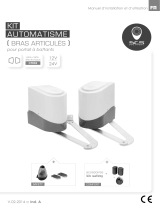
KIT AUTOMATISME
( VÉRINS )
pour portail à battants

TABLE DES MATIÈRES
1.1 PRÉCAUTIONS POUR L'INSTALLATEUR
1.2 INSTALLATION
A. INSTALLATION DE L’AUTOMATISME
B. TABLEAU DE DIMENSIONS
C. FIXATION DU MOTEUR
D. BRANCHEMENT DES FILS
E. DÉVERROUILLAGE D’URGENCE
1.3 CARACTÉRISTIQUES TECHNIQUES
A. DIMENSIONS
B. CARACTÉRISTIQUES TECHNIQUES
1.4 MAINTENANCE
P.1
P.2
P.2
P.2
P.3
P.3
P.4
P.4
P.4
P.5
P.5
Basse tension
24V
24V pour plus
de sécurité
Durable
Matériaux solides
pour usage durable
Facile
L'installation et
l'interface utilisateur
conviviale et simple
Silencieux
Un système
silencieux pour
plus de confort
Déverrouillage manuel
facile pour une
meilleure protection
Déverrouillage

A
1
1.2 INSTALLATION
2x1.5 mm2
4x0.5 mm2
TX - 4x0.5 mm2
RX - 4x0.5 mm2
2x1.5 mm2
2x1.5 mm2
4
6
23
1
4
5
5
1.1 PRÉCAUTIONS POUR L'INSTALLATEUR
ATTENTION !
Ce manuel est uniquement destiné aux techniciens qualifiés, spécialisés
dans les installations d’automatismes de portail.
(1) Toutes les installations, les branchements électriques, les ajustements et les tests ne doivent
être effectués qu'après une lecture attentive et une bonne compréhension des instructions.
(2) Avant de commencer toute opération d'installation ou d'entretien, débranchez l'alimentation
électrique.
(3) Assurez-vous que la structure existante est conforme aux normes en termes de résistance
et de stabilité.
(4) Si nécessaire, raccorder le portail motorisé à la terre pendant la phase de raccordement au
réseau électrique.
(5) L'installation nécessite un personnel qualifié avec des compétences mécaniques et électriques.
(6) Placez les commandes automatiques hors de portée des enfants.
(7) Pour remplacer ou réparer le système motorisé, utilisez uniquement des pièces d’origine.
Aucun dommage causé par l’utilisation de pièces d’autres provenances et des méthodes
non conformes à celles indiquées dans ce manuel ne seront approuvées et reconnues
par le fabricant.
(8) En cas de doute, ne jamais faire fonctionner l’installation au risque de l’endommager.
(9) N’utilisez la télécommande que lorsque vous avez une vue complète du portail.
INSTALLATION DE L’AUTOMATISME
1. 24V DC feu clignotant
antenne intégrée
2. Bouton
3. Centrale de commande
4. Photocellule
5. 24V DC automatimse portail battant
6. Telecommande

B
2
TABLEAU DE DIMENSION
Pour une installation correcte, conformez-vous scrupuleusement aux mesures indiquées
sur le tableau ci-dessous.
Si nécessaire, ajuster la structure du portail pour l'adapter à votre motorisation.
Avant de procéder à l'installation, assurez-vous que votre portail fonctionne librement :
1) Les charnières sont positionnées correctement et sont graissés.
2) Aucun obstacle dans la zone de déplacement.
3) Pas de frictions entre les deux portails ou au niveau du sol pendant l’ouverture.

C
D
3
94
20
82
no.1
Blanc(+)
Jaune(-)
Rouge(5V)
Vert(Signal)
Noir(GND)
Moteur
Moteur
Capteur à encodeur
Capteur à encodeur
Capteur à encodeur
1
2
3
4
5
1
2
3
4
5
A
B
no.2
FIXATION DU MOTEUR
Assembler le support et le fixer sur le pilier.
BRANCHEMENT DES FILS
Retirez le couvercle et fixez le support avec la goupille.
Libérez l'automatisme et placez la goupille selon les plans de montage no. 1 et no. 2.
Assurez-vous que les automatismes de portails soient montés en position horizontale et fonctionnent
mécaniquement jusqu’aux positions suivantes.
1) Portail en position "FERMÉ".
2) Portail en position "OUVERT".
3) Portail en position " angle de 45°.
Pour positionner votre patte de fixation sur le portail, à l’aide d’une batterie, déployez complètement
votre vérin et rentrez-le d’un centimètre.

EDÉVERROUILLAGE D'URGENCE
4
1.3 CARACTÉRISTIQUES TECHNIQUES
Dimensions
Déverrouillage du motoréducteur
1). Insérer la clé de deverrouillage dans la fente.
2). Tourner la clé de déverrouillage dans le sens inverse des aiguilles d'une montre.
3). Tirer sur la barre de deverrouillage.
4). Tourner la clé de déverrouillage dans le sens horaire pour fixer la barre. Lorsque vous
tournez la clé de déverrouillage (dans le sens horaire), la barre doit être en position tirée .
5). La direction de rotation est inversée pour le moteur droit.
1. 2.
3. 4.
675mm
Axé 640mm
117mm
190mm
A

B
5
CARACTÉRISTIQUES TECHNIQUES
1.4 MAINTENANCE
Effectuer les opérations suivantes au moins tous les 6 mois.
En cas d'utilisation fréquente, raccourcir ce délai.
Couper l'alimentation:
(1) Nettoyer et graisser les vis, les chevilles et la charnière.
(2) Vérifier que les points de fixation soient bien serrés.
(3) Vérifier la bonne connexion du câble.
Connecter l'alimentation:
(1) Vérifier les réglages de l'alimentation.
(2) Vérifier le fonctionnement du déverrouillage manuel.
(3) Vérifier le bon fonctionnement des photocellules ou autre dispositif de sûreté.
Moteur
Type
Force de poussée
Course
Tension d’alimentation
Absorption
Intensité
Poids max vantail
Largeur max vantail
Température de fonctionnement
Dimensions
Poids
Moteur 24Vdc avec déverrouillage
Motoréducteur
1500N
350mm
24Vdc
2A
4.2A pour max 10 seconds
200kg
2 m
20oC~+50oC
675mm x 95mm x 190mm
3.1kg
Assistance
téléphonique (Fr)
Du lundi au vendredi : 9h>12h - 14h>18h
Tél. 02 51 61 01 21
0 810 90 24 21
(coût d’un appel local)

Installation and user manual
Comfort
kit
Safety
kit
Motors
Control unit
2 remote control
Blinker
Motors
Control unit
2 remote control
Blinker
Photocells
( CYLINDERS )
for swing gates
24V Encoding
system
intensive1A
AUTOMATION KIT
EN

INDEX
1.1 General Safety Precaution
1.2 Installation
A. Standard Installation
B. Dimension Chart
C. Motor Fixing
D. Wire Connection
E. Emergency Release
1.3 Technical Features
A. Dimension
B. Technical Feature
1.4 Maintenance
P.1
P.2
P.2
P.2
P.3
P.3
P.4
P.4
P.4
P.5
P.5
Low Voltage
24V
24V power supply
for great safety
Durability
Solid material apply
with lasting usage
EZ Instal
Easy installation
and user friendly
interface
Silence
Worm gear application
give silence operation
Manual release device
with easy use and
highly protection
Key Release

ASTANDARD INSTALLATION
1.1 GENERAL PRECAUTION:
1. 24V DC blinker with antenna
2. Push Button
3. Control Box
4. Photo Sensor
5. 24V DC gate opener
6. Transmitter
1
1.2 STANDARD INSTALLATION
2x1.5 mm2
4x0.5 mm2
TX - 4x0.5 mm2
RX - 4x0.5 mm2
2x1.5 mm2
2x1.5 mm2
WARNING :
This user manual is only for qualified technicians who is specialized in installations and automations.
(1) All installations, electrical connections, adjustments and testing must be performed only after
reading and understanding of all instructions carefully.
(2) Before carrying out any installation or maintenance operation, disconnect the electrical power
supply by turning off the magneto thermic switch connected upstream and apply the hazard area
notice required by applicable regulations
(3) Make sure the existing structure is up to standard in terms of strength and stability
(4) When necessary, connect the motorized gate to reliable earth system during electricity connection phase.
(5) Installation requires qualified personnel with mechanical and electrical skills.
(6) Keep the automatic controls (remote, push bottom, key selectors…etc) being placed properly
and away from children.
(7) For replace or repair of the motorized system, only original parts must be applied. Any damage
caused by inadequate parts and methods will not be claimed to motor manufacturer.
(8) Never operate the drive if you have any suspect with what it might be faulty or damage to the system.
(9) The motors are exclusively designed for the gate opening and closing application, any other
usage is deemed inappropriate. The manufacture should not be liable for any damage resulting
from the improper use. Improper usage should void all warranty, and the user accepts sole
responsibility for any risks thereby may accrue.
(10) The system may only be operated in proper working order. Always follow the standard procedures
by following the instructions in this installation and operating manual.
(11) Only command the remote when you have a full view of the gate.
Please keep this installation manual for future reference.
4
6
23
1
4
5
5

BDIMENSION CHART
2
Comply with the measures shown on the chart for proper installation. Adjust the gate structure
to fit it for best automation, if necessary.
Before preceding the installation, be sure that gate moves freely and that:
1) Hinges are properly positioned and greased.
2) No obstacles in the moving area.
3) No frictions between two gate leafs or with the ground while moving

CMOTOR FIXING
Assemble the rear bracket and fix it on the pillar.
DWIRE CONNECTION:
3
94
20
82
Release the gate opener and place the pin into the fitting position no.1 and no. 2.
Make sure the gate openers are mounted in horizontal position especially in those positions.
1) Gate in “CLOSE” position
2) Gate in “OPEN” position
3) Gate at “45。angle” position
Prior to weld the bracket on the gate leaf(if necessary), cover the gate opener to prevent
damages from sparks.
To place your bracket on the gate, with a battery, fully deploy your cylinder and tuck it a centimeter.
no.1
White(+)
Yellow(-)
Red(5V)
Green(Signal)
Black(GND)
Motor
Motor
Hall Sensor
Hall Sensor
Hall Sensor
1
2
3
4
5
1
2
3
4
5
A
B
no.2

EEMERGENCY RELEASE
4
1.3 TECHNICAL FEATURES :
Dimension:
Gear Motor Release (for left motor)
1). Insert the release key to the release slot
2). Turn the release key anti-clockwise
3). Pull out the release bar
4). Turn the release key clockwise to fix the release bar, the release bar has to be in pulled
out position when you turn the release key clockwise
5). The turning direction will be reversed for right motor.
1. 2.
3. 4.
117mm
190mm
A
675mm
Axed 640mm

B
5
Technical Feature:
1.4 Maintenance:
Conduct the following operations at least every 6 months. If in high intensity of use,
shorten the period in between.
Disconnect the power supply:
(1) Clean and lubricate the screws, the pins, and the hinge with grease.
(2) Check the fastening points are properly tightened.
(3) Make the wire connection are in good condition.
Connect the power supply:
(1) Check the power adjustments.
(2) Check the function of the manual release.
(3) Check the function of photocells or other safety devise.
Motor
Gear type
Thrust
Stroke length
Power supply
Maximum operating
Maximum gate weight
Maximum gate length
Operating Temperature
Dimension
Weight
24Vdc motor with mechanical release
Worm gear
1500N
350mm
24Vdc
4.2A for maximum 10 seconds.
200 kg per leaf
2 meters
-20oC~+50oC
675mm x 95mm x 190mm
3.1kg
Hotline (Fr)
From monday to friday : 9
h
>12
h
- 14
h
>18
h
00 33 (0)2 51 61 01 21
(coût d’un appel local)

LIEU D’ACHAT
enseigne : .............................................................................. Date d’achat : ................................
ville : .................................................................................................. CP : .......................................
VOUS
société : ................................................................................... ............................................................
nom : ........................................................... prénom : ....................................................................
siret : ................................................................................... .................................................................
tél. : .................................................. email : ....................................................................................
ville : .............................................................................. CP : ...........................................................
!
VOTRE PRODUIT
nom : kit automatisme pour portail à battants INTENSIVE1A
code barre (numéro à 13 chiffres) : ................................................................................................
N° lot (indiqué dans la zone du code barre du packaging) : .....................................................
GARANTIE 3 ANS
DÉCLARATION DE GARANTIE
À RENVOYER :
auprès de votre installateur ou distributeur
N’oubliez pas d’enregistrer votre garantie dans le mois suivant votre achat.
Conservez soigneusement votre justicatif d’achat, il vous sera demandé pour faire jouer la garantie.

PURCHASE LOCATION
company : .................................................................... date of purchase : .....................................
city : .............................................................................. zip code : .................................................
YOU
company : ................................................................................... .......................................................
name : ........................................................... surname : ................................................................
phone : .................................................. email : .............................................................................
city : .............................................................................. zip code : .................................................
!
YOUR PRODUCT
product name : automation kit for swing gates INTENSIVE1A
gencod (13 numbers) : ......................................................................................................................
batch number (close to gencod location) : ..................................................................................
WARRANTY 3 YEARS
WARRANTY DECLARATION
TO RETURN TO :
your installer or distributor.
To be send at least 1 month after purchasing. Please keep your proof of purchase.

!
MES COORDONNÉES
Entreprise : ....................................................................................... SIRET : ................................................
Nom : ........................................................... Prénom : ................................................................................
Tél. : .................................................. email : ...............................................................................................
adresse .................................................. ..........................................................................................................
Ville : .............................................................................. CP : ......................................................................
À RETOURNER PAR COURRIER À :
Système de Communication et de Sécurité SA
service commande - Rte de St Symphorien - BP 69 - 85130 Les Landes génusson (FRANCE)
BON DE COMMANDE
Référence produit Référence PU TTC Qté Sous-total
TELECOMMANDE INTENSIVE 3760074139910 25,80€ x =
LOT 2 PHOTOCELLULES INTENSIVE 3760074139606 27,80€ x =
SÉLECTEUR À CLÉS 3760074132355 24,40€ x =
CLAVIER CODE XO 006A 3760074130085 32,40€ x =
GACHE APPLIQUE XO 201 3760074130146 30,50€ x =
SERRURE ELECTRIQUE XO 404 3760074131198 42,50€ x =
RADIOCOMMANDE UNIVERSELLE INTENSIVE
3760074139927 56,80€ x =
PANNEAU SOLAIRE 12/24V 3760074131303 141,10€ x =
montant
total produit €
frais de port €
TOTAL €
FRAIS DE PORT*
paiement par chèque
1 produit 7.12€
2-3 produits 9.50€
4-10 produits 11.90€
10+ produits 17.90€
* Les frais de livraison sont exclusivement valables pour la France métropolitaine
Prix valables jusqu’au 1er janvier 2015
certains produits ont une
majoration sur les frais de
livraison, référez-vous au
tableau ci-dessus.


pour tout problème technique,
veuillez contacter votre installateur
ou distributeur.
/