Maintenance Manual
Site Master
Cable and Antenna Analyzer with
Spectrum Analyzer
S331E, 2 MHz to 4 GHz
S332E, 2 MHz to 4 GHz, Spectrum Analyzer, 9 kHz to 4 GHz
S361E, 2 MHz to 6 GHz
S362E, 2 MHz to 6 GHz, Spectrum Analyzer, 9 kHz to 6 GHz
Anritsu Company
490 Jarvis Drive
Morgan Hill, CA 95037-2809
USA
Part Number: 10580-00253
Revision: J
Published: May 2016
Copyright 2010, 2016 Anritsu Company


TRADEMARK ACKNOWLEDGMENTS
Windows, Windows XP, and Windows Vista are all registered trademarks of Microsoft Corporation.
Acrobat Reader is a registered trademark of Adobe Corporation.
Site Master is a trademark of Anritsu Company.
NOTICE
Anritsu Company has prepared this manual for use by Anritsu Company personnel and customers as a guide for the
proper installation, operation and maintenance of Anritsu Company equipment and computer programs. The
drawings, specifications, and information contained herein are the property of Anritsu Company, and any
unauthorized use or disclosure of these drawings, specifications, and information is prohibited; they shall not be
reproduced, copied, or used in whole or in part as the basis for manufacture or sale of the equipment or software
programs without the prior written consent of Anritsu Company.
UPDATES
Updates, if any, can be downloaded from the Documents area of the Anritsu Website at:
http://www.anritsu.com
For the latest service and sales contact information in your area, please visit:
http://www.anritsu.com/contact.asp


S3xxE MM PN: 10580-00253 Rev. J Safety-1
Safety Symbols
To prevent the risk of personal injury or loss related to equipment malfunction, Anritsu Company uses the
following symbols to indicate safety-related information. For your own safety, please read the information
carefully before operating the equipment.
Symbols Used in Manuals
Safety Symbols Used on Equipment and in Manuals
The following safety symbols are used inside or on the equipment near operation locations to provide
information about safety items and operation precautions. Ensure that you clearly understand the meanings of
the symbols and take the necessary precautions before operating the equipment. Some or all of the following
five symbols may or may not be used on all Anritsu equipment. In addition, there may be other labels attached
to products that are not shown in the diagrams in this manual.
Danger
This indicates a risk from a very dangerous condition or procedure that could result in
serious injury or death and possible loss related to equipment malfunction. Follow all
precautions and procedures to minimize this risk.
Warning
This indicates a risk from a hazardous condition or procedure that could result in
light-to-severe injury or loss related to equipment malfunction. Follow all precautions
and procedures to minimize this risk.
Caution
This indicates a risk from a hazardous procedure that could result in loss related to
equipment malfunction. Follow all precautions and procedures to minimize this risk.
This indicates a prohibited operation. The prohibited operation is indicated symbolically
in or near the barred circle.
This indicates a compulsory safety precaution. The required operation is indicated
symbolically in or near the circle.
This indicates a warning or caution. The contents are indicated symbolically in or near
the triangle.
This indicates a note. The contents are described in the box.
These indicate that the marked part should be recycled.

Safety-2 PN: 10580-00253 Rev. J S3xxE MM
For Safety
Warning
Always refer to the operation manual when working near locations at which
the alert mark, shown on the left, is attached. If the operation, etc., is
performed without heeding the advice in the operation manual, there is a
risk of personal injury. In addition, the equipment performance may be
reduced.
Moreover, this alert mark is sometimes used with other marks and
descriptions indicating other dangers.
Warning
When supplying power to this equipment, connect the accessory 3-pin
power cord to a 3-pin grounded power outlet. If a grounded 3-pin outlet is
not available, use a conversion adapter and ground the green wire, or
connect the frame ground on the rear panel of the equipment to ground. If
power is supplied without grounding the equipment, there is a risk of
receiving a severe or fatal electric shock.
Warning
This equipment can not be repaired by the operator. Do not attempt to
remove the equipment covers or to disassemble internal components.
Only qualified service technicians with a knowledge of electrical fire and
shock hazards should service this equipment. There are high-voltage parts
in this equipment presenting a risk of severe injury or fatal electric shock to
untrained personnel. In addition, there is a risk of damage to precision
components.
Warning
Use two or more people to lift and move this equipment, or use an
equipment cart. There is a risk of back injury if this equipment is lifted by
one person.
Caution
Electrostatic Discharge (ESD) can damage the highly sensitive circuits in
the instrument. ESD is most likely to occur as test devices are being
connected to, or disconnected from, the instrument’s front and rear panel
ports and connectors. You can protect the instrument and test devices by
wearing a static-discharge wristband. Alternatively, you can ground
yourself to discharge any static charge by touching the outer chassis of the
grounded instrument before touching the instrument’s front and rear panel
ports and connectors. Avoid touching the test port center conductors
unless you are properly grounded and have eliminated the possibility of
static discharge.
Repair of damage that is found to be caused by electrostatic discharge is
not covered under warranty.

S3xxE MM PN: 10580-00253 Rev. J Safety-3
For Safety
Warning
This equipment is supplied with a rechargeable battery that could potentially leak hazardous
compounds into the environment. These hazardous compounds present a risk of injury or loss
due to exposure. Anritsu Company recommends removing the battery for long-term storage of
the instrument and storing the battery in a leak-proof, plastic container. Follow the
environmental storage requirements specified in the product data sheet.

Safety-4 PN: 10580-00253 Rev. J S3xxE MM

S3xxE MM PN: 10580-00253 Rev. J Contents-1
Table of Contents
Chapter 1—General Information
1-1 Introduction . . . . . . . . . . . . . . . . . . . . . . . . . . . . . . . . . . . . . . . . . . . . . . . . . . . . . . . . . . . . . . . . 1-1
1-2 Anritsu Customer Service Centers . . . . . . . . . . . . . . . . . . . . . . . . . . . . . . . . . . . . . . . . . . . . . . 1-1
1-3 Recommended Test Equipment . . . . . . . . . . . . . . . . . . . . . . . . . . . . . . . . . . . . . . . . . . . . . . . . 1-2
1-4 Replaceable Parts . . . . . . . . . . . . . . . . . . . . . . . . . . . . . . . . . . . . . . . . . . . . . . . . . . . . . . . . . . 1-4
Chapter 2—Spectrum Analyzer Verification
2-1 Frequency Accuracy Verification and Adjustment . . . . . . . . . . . . . . . . . . . . . . . . . . . . . . . . . . 2-1
2-2 Single Side Band (SSB) Phase Noise Verification . . . . . . . . . . . . . . . . . . . . . . . . . . . . . . . . . . 2-3
2-3 Spurious Response (Second Harmonic Distortion) Verification . . . . . . . . . . . . . . . . . . . . . . . . 2-4
2-4 Resolution Bandwidth Accuracy Verification . . . . . . . . . . . . . . . . . . . . . . . . . . . . . . . . . . . . . . 2-6
RBW Test . . . . . . . . . . . . . . . . . . . . . . . . . . . . . . . . . . . . . . . . . . . . . . . . . . . . . . . . . . . . . . 2-6
2-5 Spectrum Analyzer Absolute Amplitude Accuracy Verification. . . . . . . . . . . . . . . . . . . . . . . . . 2-7
50 MHz Amplitude Accuracy Verification. . . . . . . . . . . . . . . . . . . . . . . . . . . . . . . . . . . . . . . 2-7
Amplitude Accuracy Across Frequency Verification . . . . . . . . . . . . . . . . . . . . . . . . . . . . . 2-10
2-6 Residual Spurious Response Verification. . . . . . . . . . . . . . . . . . . . . . . . . . . . . . . . . . . . . . . . 2-14
Residual Spurious Response Test with Preamp Off . . . . . . . . . . . . . . . . . . . . . . . . . . . . . 2-14
Residual Spurious Response Test with Preamp On . . . . . . . . . . . . . . . . . . . . . . . . . . . . . 2-15
2-7 Displayed Average Noise Level (DANL). . . . . . . . . . . . . . . . . . . . . . . . . . . . . . . . . . . . . . . . . 2-16
2-8 Third Order Intercept (TOI) Verification . . . . . . . . . . . . . . . . . . . . . . . . . . . . . . . . . . . . . . . . . 2-18
Chapter 3—Cable and Antenna Analyzer Verification
3-1 Frequency Accuracy Verification . . . . . . . . . . . . . . . . . . . . . . . . . . . . . . . . . . . . . . . . . . . . . . . 3-1
3-2 Return Loss Accuracy Verification . . . . . . . . . . . . . . . . . . . . . . . . . . . . . . . . . . . . . . . . . . . . . . 3-2
Chapter 4—Option Verification
4-1 Introduction . . . . . . . . . . . . . . . . . . . . . . . . . . . . . . . . . . . . . . . . . . . . . . . . . . . . . . . . . . . . . . . . 4-1
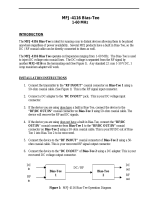
4-2 Option 10, Bias Tee Verification . . . . . . . . . . . . . . . . . . . . . . . . . . . . . . . . . . . . . . . . . . . . . . . . 4-1
Low Current Test Verification . . . . . . . . . . . . . . . . . . . . . . . . . . . . . . . . . . . . . . . . . . . . . . . 4-1
High Current Test Verification . . . . . . . . . . . . . . . . . . . . . . . . . . . . . . . . . . . . . . . . . . . . . . . 4-2
Fault Verification . . . . . . . . . . . . . . . . . . . . . . . . . . . . . . . . . . . . . . . . . . . . . . . . . . . . . . . . . 4-3
4-3 Option 21, Transmission Measurement, System Dynamic Range . . . . . . . . . . . . . . . . . . . . . . 4-4
4-4 Option 29, Power Meter Level Accuracy . . . . . . . . . . . . . . . . . . . . . . . . . . . . . . . . . . . . . . . . . 4-5
4-5 Option 31, GPS Verification . . . . . . . . . . . . . . . . . . . . . . . . . . . . . . . . . . . . . . . . . . . . . . . . . . . 4-7
Frequency Accuracy Verification (Only for models S332E and S362E) . . . . . . . . . . . . . . . 4-7
GPS Antenna Bias Tee Verification. . . . . . . . . . . . . . . . . . . . . . . . . . . . . . . . . . . . . . . . . . . 4-8
Chapter 5—Battery Information
5-1 General Information . . . . . . . . . . . . . . . . . . . . . . . . . . . . . . . . . . . . . . . . . . . . . . . . . . . . . . . . . 5-1
5-2 Battery Pack Removal and Replacement . . . . . . . . . . . . . . . . . . . . . . . . . . . . . . . . . . . . . . . . 5-2

Contents-2 PN: 10580-00253 Rev. J S3xxE MM
Table of Contents (Continued)
Chapter 6—Assembly Replacement
6-1 Opening the Site Master Case . . . . . . . . . . . . . . . . . . . . . . . . . . . . . . . . . . . . . . . . . . . . . . . . . 6-1
6-2 PCB Assembly Removal. . . . . . . . . . . . . . . . . . . . . . . . . . . . . . . . . . . . . . . . . . . . . . . . . . . . . . 6-3
6-3 SPA Assembly Replacement . . . . . . . . . . . . . . . . . . . . . . . . . . . . . . . . . . . . . . . . . . . . . . . . . . 6-4
6-4 SPA and MB/VNA N Connector Replacement . . . . . . . . . . . . . . . . . . . . . . . . . . . . . . . . . . . . . 6-5
6-5 GPS (Opt. 31) Replacement. . . . . . . . . . . . . . . . . . . . . . . . . . . . . . . . . . . . . . . . . . . . . . . . . . . 6-6
6-6 Option Assembly Replacement. . . . . . . . . . . . . . . . . . . . . . . . . . . . . . . . . . . . . . . . . . . . . . . . . 6-7
6-7 Motherboard/VNA Assembly Replacement . . . . . . . . . . . . . . . . . . . . . . . . . . . . . . . . . . . . . . . 6-7
6-8 Fan Assembly Replacement . . . . . . . . . . . . . . . . . . . . . . . . . . . . . . . . . . . . . . . . . . . . . . . . . . 6-8
6-9 LCD Assembly Replacement . . . . . . . . . . . . . . . . . . . . . . . . . . . . . . . . . . . . . . . . . . . . . . . . . . 6-9
6-10 LCD Backlight PCB Removal and Replacement . . . . . . . . . . . . . . . . . . . . . . . . . . . . . . . . . . 6-11
6-11 Keypad and Keypad PCB Replacement . . . . . . . . . . . . . . . . . . . . . . . . . . . . . . . . . . . . . . . . 6-12
6-12 Touch Screen Replacement . . . . . . . . . . . . . . . . . . . . . . . . . . . . . . . . . . . . . . . . . . . . . . . . . 6-13
Chapter 7—Troubleshooting
7-1 Introduction . . . . . . . . . . . . . . . . . . . . . . . . . . . . . . . . . . . . . . . . . . . . . . . . . . . . . . . . . . . . . . . . 7-1
7-2 Turn-on Problems . . . . . . . . . . . . . . . . . . . . . . . . . . . . . . . . . . . . . . . . . . . . . . . . . . . . . . . . . . . 7-1
7-3 Other Problems. . . . . . . . . . . . . . . . . . . . . . . . . . . . . . . . . . . . . . . . . . . . . . . . . . . . . . . . . . . . . 7-2
Appendix A—Test Records
A-1 Test Records for Spectrum Analyzer Verification . . . . . . . . . . . . . . . . . . . . . . . . . . . . . . . . . . A-2
A-2 Test Records for Cable and Antenna Analyzer Verification . . . . . . . . . . . . . . . . . . . . . . . . . . A-12
A-3 Test Records for Options Verification . . . . . . . . . . . . . . . . . . . . . . . . . . . . . . . . . . . . . . . . . . . A-13

S3xxE MM PN: 10580-00253 Rev. J 1-1
Chapter 1 — General Information
1-1 Introduction
This manual provides maintenance instructions for Anritsu Site Master Models S331E, S332E, S361E and
S362E. The manual includes:
• General information in this chapter, including:
• Lists of necessary test equipment to perform verification testing
(Table 1-1, Table 1-2, and Table 1-3)
• Replaceable parts list (Table 1-4)
• Performance verification procedures:
• Chapter 2, “Spectrum Analyzer Verification”
• Chapter 3, “Cable and Antenna Analyzer Verification”
• Chapter 4, “Option Verification”
• Battery pack information (Chapter 5, “Battery Information”)
• Parts replacement procedures (Chapter 6, “Assembly Replacement”)
• Blank test records are included in Appendix A.
• Copy the blank test records from Appendix A and use them to record measured values. These test
records form a record of the performance of the instrument. Anritsu recommends that you make a
copy of the blank test records to document the measurements each time a Performance
Verification is performed. Continuing to document this process each time it is performed provides
a detailed history of instrument’s performance, allowing trends to be observed.
Familiarity with the basic operation of the front panel keys (for example, how to change measurement mode,
preset the unit, or the meaning of soft key or submenu) is assumed.
1-2 Anritsu Customer Service Centers
For the latest service and sales information in your area, please visit the following URL:
http://www.anritsu.com/Contact.asp
Choose a country for regional contact information.
Caution Before making any measurement, verify that all equipment has warmed up for at least 30 minutes.

1-3 Recommended Test Equipment General Information
1-2 PN: 10580-00253 Rev. J S3xxE MM
1-3 Recommended Test Equipment
The following test equipment is recommended for use in testing and maintaining Anritsu Site Master
Model S3xxE. Table 1-1 is a list of test equipment that is required for verifying the Spectrum Analyzer
functions. Table 1-2 is a list of test equipment that is required for verifying the Cable and Antenna Analyzer.
Table 1-3 is a list of test equipment that is required for verifying the functions of installed options.
a. MG3692A models require Option 15 to achieve power of +16 dBm at 3.5 GHz. MG3692B models do not require Option 15 to
achieve power of +16 dBm at 3.5 GHz.
Table 1-1. Test Equipment Required for Verifying Spectrum Analyzer Functions
Instrument Critical Specification
Recommended
Manufacturer/Model
Synthesized Signal Generator Frequency: 0.1 Hz to 20 GHz,
Power Output: +16 dBm,
Step attenuator installed
Anritsu Model MG3692A/B/C
(Qty 2)
with Options 2A, 3, 4, 22, 15x
a
Power Meter Power Range: –70 dBm to +20 dBm Anritsu Model ML2438A
Power Sensor Frequency: 10 MHz to 18 GHz
Power Range: –67 dB to +20 dB
Anritsu Model MA2442D (Qty 2)
Frequency Reference Frequency: 10 MHz Symmetricom RubiSource T&M
Fixed Attenuator 10 dB Attenuation Aeroflex/Weinschel Model 44-10
Fixed Attenuator 2 dB Attenuation Aeroflex/Weinschel Model 44-2
(Qty 2)
Fixed Attenuator 6 dB Attenuation Aeroflex/Weinschel Model 44-6
(Qty 2)
Fixed Attenuator 20 dB Attenuation Aeroflex/Weinschel Model 44-20
(Qty 2)
Low Pass Filter 50 MHz Low Pass Filter Anritsu Model 1030-96
Power Splitter Frequency: DC to 18 GHz Aeroflex/Weinschel Model 1870A
Adapter Frequency: DC to 20 GHz
N(m) to N(m), 50 ohm
Anritsu Model 34NN50A
Adapter Frequency: DC to 20 GHz
N(m) to N(m), 50 ohm
Anritsu Model 34RKNF50
50 ohm Termination Frequency: DC to 18 GHz Anritsu Model 28N50-2
RF Coaxial Cable Frequency: DC to 18 GHz
N(m) to N(m), 50 ohm
Anritsu Model 15NN50-1.5C
Coaxial Cable BNC(m) to BNC(m), 50 ohm Anritsu Model 2000-1627-R

General Information 1-3 Recommended Test Equipment
S3xxE MM PN: 10580-00253 Rev. J 1-3
Table 1-2. Test Equipment Required for Cable and Antenna Analyzer Verification
Instrument Critical Specification Recommended Manufacturer/Model
Frequency Counter Frequency: 2 GHz Anritsu Model MF2412B
Open/Short Frequency: DC to 18 GHz Anritsu Model 22N50
Termination Frequency: DC to 18 GHz
Return Loss: 40 dB min.
Anritsu Model 28N50-2
RF Coaxial Cable Frequency: DC to 18 GHz
N(m) to N(f), 50 ohm
Anritsu Model 15NN50-1.5C
6 dB Offset Termination Frequency: DC to 6.0 GHz Anritsu Model SC7424
20 dB Offset Termination Frequency: DC to 6.0 GHz Anritsu Model SC7423
Table 1-3. Test Equipment Required for Verifying Options
Instrument Critical Specification Recommended Manufacturer/Model
Termination Frequency: DC to 18 GHz
Return Loss: 40 dB min.
Anritsu Model 28N50-2
Termination Frequency: DC to 18 GHz
Return Loss: 40 dB min.
Anritsu Model 28NF50-2
Adapter 40 ohm Load Anritsu Model T2904
Adapter 78 ohm Load Anritsu Model T3536
Adapter 105 ohm Load Anritsu Model T3377
Adapter SMA to BNC(f) Pomona 4290 or equivalent
Adapter GPS Terminator Amphenol B1004A1-ND3G-93R-0.05-1W
or equivalent
Adapter Frequency: DC to 20 GHz
N(m) to N(m), 50 ohm
Anritsu Model 34NN50A
Adapter Frequency: DC to 20 GHz
K(m) to N(f), 50 ohm
Anritsu Model 34RKNF50
GPS Antenna Anritsu 2000-1528-R
Coaxial Cable Frequency: DC to 18 GHz
N(m) to N(m), 50 ohm
Anritsu Model 15NN50-1.5C
Coaxial Cable BNC(m) to BNC(m), 50 ohm Any (Qty 2) Anritsu Model 2000-1627-R
Synthesized Signal Source Frequency: 0.1 Hz to 20 GHz
Power Output to +13 dBm
Anritsu Model MG3692A or B with
Options 2A, 4, 22, 15
a
a. Option 15 is required for MG3692A models to achieve power of +13 dBm. MG3692B models do not require Option 15.
Power Meter Power Range: − 70 to +20 dBm Anritsu Dual Channel Model ML2438A
Power Sensor Frequency: 10 MHz to 18 GHz
Power Range: –67 to +20 dB
Anritsu Model MA2442D (quantity 2)
Fixed Attenuator 10 dB Attenuation Aeroflex/Weinschel Model 44-10
Power Splitter Frequency: DC to 18 GHz Aeroflex/Weinschel Model 1870A
Frequency Reference Frequency: 10 MHz Symmetricom Model RubiSource T&M

1-4 Replaceable Parts General Information
1-4 PN: 10580-00253 Rev. J S3xxE MM
1-4 Replaceable Parts
Table 1-4. List of Replaceable Parts
Part Number Description
ND70931 S331E MB/VNA PCB Assembly (units without Option 21)
a
s/n < 1128048 and 1128247,
1129004
ND73215 S331E MB/VNA PCB Assembly (units without Option 21)
a
s/n > 1128047 except
1128247, 1129004, and s/n < 1226201, plus some additional units per Service Note
S3xxE-035
ND75282 S331E MB/VNA PCB Assembly with Locking connector (units without Option 21)
a
1233006 < s/n < 1608000, and some additional units per Service Note S3xxE-035
ND82168 S331E MB/VNA PCB Assembly(units without Option 21)
a
s/n > 1608000
ND70932 S331E MB/VNA PCB Assembly (units with Option 21)
a
s/n < 1123047 and 1123058
ND73217 S331E MB/VNA PCB Assembly (units with Option 21)
a
s/n > 1123046 except 1123058,
and s/n < 1226201, plus some additional units per Service Note S3xxE-035
ND75284 S331E MB/VNA PCB Assembly with Locking connector (units with Option 21)
a
1233006 <
s/n < 1608000, plus some additional units per Service Note S3xxE-035
ND82169 S331E MB/VNA PCB Assembly(units with Option 21)
a
s/n > 1608000
ND70929 S361E MB/VNA PCB Assembly (units without Option 21)
a
s/n < 1128183 except 1127057
and 1125052
ND73216 S361E MB/VNA PCB Assembly (units without Option 21)
a
s/n > 1128182 and also
1127057, 1125052, and s/n < 1229073, except for 1228080, 1228175, 1229063
ND75283 S361E MB/VNA PCB Assembly with Locking connector (units without Option 21)
a
1229072 < s/n < 1606000, and also 1228080, 1228175, 1229063
ND82170 S361E MB/VNA PCB Assembly(units without Option 21)
a
s/n > 1606000
ND70933 S361E MB/VNA PCB Assembly (units with Option 21)
a
s/n < 1128183 except 1127057
and 1125052
ND73218 S361E MB/VNA PCB Assembly (units with Option 21)
a
s/n > 1128182 and 1127057,
1125052, and s/n < 1229073, except for 1228080, 1228175, 1229063
ND75285 S361E MB/VNA PCB Assembly with Locking connector (units with Option 21)
a
1229072 <
s/n < 1606000, and also 1228080, 1228175, 1229063
ND82171 S361E MB/VNA PCB Assembly(units with Option 21)
a
s/n > 1606000
ND70934 S332E MB/VNA PCB Assembly
a
s/n < 1124046 and 1126145
ND73219 S332E MB/VNA PCB Assembly
a
s/n > 1124045 except 1126145 and s/n < 1227030, plus
some additional units per Service Note S3xxE-035
ND75286 S332E MB/VNA PCB Assembly with Locking connector
a
1230095 < s/n < 1606000, and
some below s/n 1230095 per Service Note S3xxE-035
ND82172 S332E MB/VNA PCB Assembly
a
s/n > 1606000
ND70936 S362E MB/VNA PCB Assembly
a
s/n < 1125034
ND73220 S362E MB/VNA PCB Assembly
a
1125033 < s/n < 1230104, except 1228065
ND75287 S362E MB/VNA PCB Assembly with Locking connector
a
1230103 < s/n < 1606000, and
also 1228065
ND82173 S362E MB/VNA PCB Assembly
a
s/n > 1606000
ND70937 S332E/S362E SPA Assembly s/n < 1124046 and 1126145 for S332E, s/n < 1125034 for
S362E
ND73221 S332E/S362E SPA Assembly s/n > 1124045 except 1126145 for S332E, s/n > 1125033
for S362E

General Information 1-4 Replaceable Parts
S3xxE MM PN: 10580-00253 Rev. J 1-5
3-67304-9 Model S331E ID Label
3-67304-6 Model S332E ID Label
3-67304-5 Model S361E ID Label
3-67304-7 Model S362E ID Label
ND70320 GPS Module (Opt 31)
ND72101 Ethernet PCB Assy (Opt 411)
ND82421 CPRI PCB Assy (Opt 751)
3-15-147 LCD Display, used with Inverter PCB (all unit s/n < 1329107, and some units with s/n
< 1334000)
3-15-165 LCD Display for S331E unit serial number range: 1334000 < s/n < 1608000, All other
S3xxE unit serial number range 1334000 < s/n < 1606000
3-15-174 LCD Display for S331E unit s/n > 1608000, all other S3xxE unit s/n > 1606000
3-68567-3 Inverter PCB (only used on all units with s/n < 1329107 and some units with s/n <
1334000)
2000-1654-R Soft Carrying Case
ND73191 Front Case with Gasket (Excludes LCD, touch screen, encoder and keypad assemblies.)
ND74508 Front Case Kit (Includes Keypad PCB, Rubber Keypad, Encoder, Encoder knob and
Speaker assy
ND73199 Back Case (Excludes Tilt Bail)
ND73201 Battery Door
633-75 7500 mAH Li-ion Battery Pack
3-513-100 RF In Connector and RF Out Connector
40-187-R AC to DC Power Converter
3-410-103 Encoder (excluding knob)
3-61360-2 Knob (excluding encoder)
ND73200 Tilt Bail Assembly
3-69770-2 Top Bumper (Gray)
3-69771-2 Bottom Bumper (Gray)
ND81940 Fan Assembly
ND75294 Main Numeric Keypad PCB (Non-Locking connector)
ND75295 Main Numeric Keypad PCB (Locking connector)
3-72773 Rubber Keypad
3-72767 Keypad Washer
3-905-2744 Keypad Screw
ND73192 Speaker
3-72758 Vent 1 (Fan Vent, above battery door)
3-72759 Vent 2 (Intake Vent, top vent on keypad side)
3-72760 Vent 3 (Battery Vent, bottom vent on keypad side)
3-72771 Cable, Keypad to Main PCB, 15 cm, white (Non-locking connectors)
3-74842-3 Cable, Keypad to Main PCB, 15 cm, white (Locking connectors)
3-72770 Cable, Keypad to Inverter PCB, 6cm, white
Table 1-4. List of Replaceable Parts
Part Number Description

1-6 PN: 10580-00253 Rev. J S3xxE MM
3-71625-1 Cable, LCD to Keypad, units with LCD Display 3-15-165
3-70675-1 Cable, LCD to Keypad, units with LCD Display 3-15-174
3-72621-4 Cable, LCD to Main PCB, units with LCD Display 3-15-147 and 3-15-165
3-70674-4 Cable, LCD to Main PCB, units with LCD Display 3-15-174
3-803-110 Cable, Ribbon, 2x20, Main PCB to SPA
3-806-197 Cable, MMCX-MMCX, DSP to SPA, 23.5 cm coaxial
ND80480 Touch Screen with Protective Film
2000-1797-R Protective Film (Touch Screen not included)
a.When ordering the Main/VNA PCB Assembly, in order to ensure installation of correct options, all options installed on the
instrument must be declared on the order. The options are listed and shown in the System (Shift-8) / Status display.
Table 1-4. List of Replaceable Parts
Part Number Description

S3xxE MM PN: 10580-00253 Rev. J 2-1
Chapter 2 — Spectrum Analyzer Verification
2-1 Frequency Accuracy Verification and Adjustment
The following procedure is used to verify and adjust the CW frequency accuracy of the Spectrum Analyzer in
the S332E and S362E Site Master. Adjustment to the frequency accuracy can be performed on units using
Application Package version 1.56 or greater.
Equipment Required
• Anritsu MG3692X Synthesized Signal Source
• 10 MHz Reference Standard
• Anritsu 34RKNF50 50 ohm Adapter
• Anritsu 15NN50-1.5C RF Coaxial Cable
• BNC male to BNC male Coaxial Cable
Procedure
1. Connect the 10 MHz Reference source to the Anritsu MG3692X Synthesized Signal Source.
2. Turn on the 10 MHz Reference Standard and the Anritsu MG3692X Synthesized Signal Source.
3. Set the MG3692X output to 1GHzCW, with an RF Output Level of –30 dBm.
4. Connect the output of the source to the RF In of the Site Master.
5. Turn on the Site Master.
6. Press the Shift key and then the Mode (9) key. Rotate the knob to highlight Spectrum Analyzer and then
press the Enter key to switch to Spectrum Analyzer mode.
7. Press the Shift key, the Preset (1) key, and then the Preset soft key to reset the instrument to the default
starting conditions.
8. Press the Shift key, the Sweep (3) key, then the Sweep Mode soft key, and press the Performance soft key.
9. Press the Amplitude soft key and then press the Reference Level soft key.
10. Use the keypad to enter –10 and press the dBm soft key.
11. Press the Span soft key, use the keypad to enter 10, and press the kHz soft key.
12. Press the BW soft key and press the RBW soft key.
13. Use the keypad to enter 100 and press the Hz soft key.
14. Press the VBW soft key, use the keypad to enter 30 and then press the Hz soft key.
15. Press the Freq soft key and press the Center Freq soft key.
16. Use the keypad to enter 1 and press the GHz soft key.
17. Press the Marker soft key, then the More soft key, set Counter Marker to On, press the Back soft key, and
then press the Peak Search soft key.
18. Verify that the marker frequency is 1 GHz ± 1.5 kHz (± 1.5 ppm). If the marker frequency is within the
specification, then record in Table A-1, “Spectrum Analyzer Frequency Accuracy”, skip Step 19 through
Note Do not connect the external 10 MHz Reference to the Site Master.
Note Without the Counter Marker On the frequency resolution will not allow viewing to kHz accuracy.

2-1 Frequency Accuracy Verification and Adjustment Spectrum Analyzer Verification
2-2 PN: 10580-00253 Rev. J S3xxE MM
Step 21, and proceed to Step 22. If the marker frequency is outside the specification, proceed to the next
step for adjustment.
19. Perform Step 19 through Step 21 only if the previous step is out of specification. Press and hold the Shift
key while simultaneously pressing the 9-5-3 keys all at once. Three quick beeps sound, and a Frequency
Calibration soft key is displayed.
20. Press the Frequency Calibration soft key. The 10 MHz Ref DAC number will be shown and can be adjusted
to bring the marker frequency within specification. Larger DAC numbers will decrease the measured
frequency and smaller DAC numbers will increase the measured frequency.
21. Adjust the DAC number by entering a new DAC value and pressing the Decimal soft key. The instrument
will take a few seconds to update, and then the peak can be remeasured using Marker, Peak Search. The
System menu will return the Frequency Calibration soft key if readjustment is necessary. Continue
adjusting the DAC value until the peak search marker value is within specification. After the
instrument is adjusted, turn the instrument power off and back on to remove the Frequency Calibration
menu. Record the marker frequency in Table A-1, “Spectrum Analyzer Frequency Accuracy”.
22. Set the MG3692X frequency to 3.9 GHz and then 5.9 GHz (for S362E only).
23. Set the S332E or S362E center freq to 3.9 GHz and then 5.9 GHz (for S362E only).
24. Press the Marker soft key, then the More soft key, set Counter Marker to On, press the Back soft key, and
then press the Peak Search soft key.
25. Verify that the marker frequency is 3.9 GHz ± 5.85 kHz (± 1.5 ppm) and then 5.9 GHz ± 8.85 kHz
(± 1.5 ppm) for the S362E only, and record in Table A-1.
Note
The following steps to adjust the frequency accuracy can be performed on instruments with
Application Package 1.56 or greater. The Application Package version can be found in the
System > Status menu as “Package Version”.
Note
If the instrument fails the Section 2-1 “Frequency Accuracy Verification and Adjustment” test, then
contact your local Anritsu Service Center (http://www.anritsu.com/Contact.asp).
Page is loading ...
Page is loading ...
Page is loading ...
Page is loading ...
Page is loading ...
Page is loading ...
Page is loading ...
Page is loading ...
Page is loading ...
Page is loading ...
Page is loading ...
Page is loading ...
Page is loading ...
Page is loading ...
Page is loading ...
Page is loading ...
Page is loading ...
Page is loading ...
Page is loading ...
Page is loading ...
Page is loading ...
Page is loading ...
Page is loading ...
Page is loading ...
Page is loading ...
Page is loading ...
Page is loading ...
Page is loading ...
Page is loading ...
Page is loading ...
Page is loading ...
Page is loading ...
Page is loading ...
Page is loading ...
Page is loading ...
Page is loading ...
Page is loading ...
Page is loading ...
Page is loading ...
Page is loading ...
Page is loading ...
Page is loading ...
Page is loading ...
Page is loading ...
Page is loading ...
Page is loading ...
Page is loading ...
Page is loading ...
Page is loading ...
Page is loading ...
Page is loading ...
Page is loading ...
Page is loading ...
Page is loading ...
Page is loading ...
Page is loading ...
Page is loading ...
Page is loading ...
Page is loading ...
Page is loading ...
Page is loading ...
Page is loading ...
Page is loading ...
Page is loading ...
Page is loading ...
Page is loading ...
Page is loading ...
Page is loading ...
/