Page is loading ...

Installation and
maintenance manual
for automations for
sectional overhead doors
and spring balanced
up-and-over doors.
(Original instructions)
GLOBE
IP1839EN- rev. 2012-07-31
DITEC S.p.A.
Via Mons. Banfi, 3 - 21042 Caronno Pertusella (VA) - ITALY
Tel. +39 02 963911 - Fax +39 02 9650314
www.ditec.it - [email protected]
EN

2
IP1839EN • 2012-07-31
INDEX
Subject Page
1. General safety precautions 3
2. Declaration of incorporation of partly completed machinery 4
2.1 Machinery Directive
4
3. Technical data 5
3.1 Operating instructions
6
3.2 Dimensions
6
4. Standard installation 7
5. Main components 8
6. Assembling belt and chain 9
7. Assembling the automation 10
8. Tensioning belt and chain 11
9. Mechanical installation 12
10. Fastening the arm 13
11. Installation of the end stops 14
12. Installation of the manual release 14
13. Installation of the GLOBEC adapter for up-and-over doors 15
14. Installation of the GLOBESI intermediate support 16
15. Electrical connections 17
16. Commands 18
17. Outputs and accessories 19
18. Settings 20
19. Radio receiver operation 22
20. Start up 23
21. Troubleshooting 24
22. Routine maintenance plan 24
23. Operating instructions 25
23.1 General safety precautions
25
23.2 Manual release instructions
26
CAPTION
i
STOP
This symbol indicates instructions or notes regarding safety issues which require particular attention.
This symbol indicates informations which are useful for correct product function.
This symbol indicates options and parameters which are only available with the indicated item.
This symbol indicates options and parameters which are not available with the indicated item.
This symbol indicates instructions or notes intended for technical and expert personnel.
This symbol indicates operations not to be effected for not compromise the correct operation of the
automation.
All right reserved
All data and specications have been drawn up and checked with the greatest care. The manufacturer cannot
however take any responsibility for eventual errors, ommisions or incomplete data due to technical or illustrative
purposes.

3
IP1839EN • 2012-07-31
1. GENERAL SAFETY PRECAUTIONS
This installation manual is intended for professionally competent personnel only.
Installation, electrical connections and adjustments must be performed in accordance with Good Working
Methods and in compliance with applicable regulations.
Before installing the product, carefully read the instructions. Bad installation could be hazardous. The packaging
materials (plastic, polystyrene, etc.) should not be discarded in the environment or left within reach of children,
as these are a potential source of hazard.
Before installing the product, make sure it is in perfect condition.
Do not install the product in an explosive environment and atmosphere: gas or inammable fumes are a serious
hazard risk.
Before installing the motors, make all structural changes relating to safety clearances and protection or segre-
gation of all areas where there is risk of being crushed, cut or dragged, and danger areas in general.
Make sure the existing structure is up to standard in terms of strength and stability. The motor manufacturer
is not responsible for failure to use Good Working Methods in building the frames to be motorized or for any
deformation occurring during use.
The safety devices (photocells, safety edges, emergency stops, etc.) must be installed taking into account:
applicable laws and directives, Good Working Methods, installation premises, system operating logic and the
forces developed by the motorized barrier.
The safety devices must protect any areas where the risk exists of being crushed, cut or gragged, or where
there are any other risks generated by the motorized barrier.
Apply hazard area notices required by applicable regulations.
Each installation must clearly show the identication details of the motorized barrier.
Before making power connections, make sure the plate details correspond to those of the power mains.
Fit an omnipolar disconnection switch with a contact opening gap of at least 3 mm.
Make sure an adequate residual current circuit breaker and overcurrent cutout are tted upstream of the elec-
trical system. When necessary, connect the motorized barrier to a reliable earth system made in accordance
with applicable safety regulations.
During installation, maintenance and repair, interrupt the power supply before opening the lid to access the
electrical parts.
To handle electronic parts, wear earthed antistatic conductive bracelets. The motor manufacturer decli-
nes all responsibility in the event of component parts being tted that are not compatible with the safe
an correct operation.
For repairs or replacements of products only original spare parts must be used. The installer shall provide all
information relating to automatic, manual and emergency operation of the motorized barrier, and provide the
user with operating instructions.

4
IP1839EN • 2012-07-31
2. DECLARATION OF INCORPORATION OF PARTLY COMPLETED MACHINERY
(Directive 2006/42/EC, Annex II-B)
The manufacturer DITEC S.p.A. with headquarters in Via Mons. Ban, 3 - 21042 Caronno Pertusella (VA) -
ITALY declares that the automation for sectional doors type GLOBE:
- has been constructed to be installed on a manual gate to construct a machine pursuant to the Directive
2006/42/EC. The manufacturer of the motorized gate shall declare conformity pursuant to the Directive
2006/42/EC (annex II-A), prior to the machine being put into service;
- conforms to applicable essential safety requirements indicated in annex I, chapter 1 of the Directive
2006/42/EC;
- conforms to the Low Voltage Directive 2006/95/EC;
- conforms to the Electromagnetic Compatibility Directive 2004/108/EC;
- technical documentation conforms to annex VII-B to the Directive 2006/42/EC;
- the technical le is managed by Renato Calza with ofces in Via Mons. Ban, 3 - 21042 Caronno Pertu-
sella (VA) - ITALY;
- a copy of technical documentation will be provided to national competent authorities, following a suitably
justied request.
Caronno Pertusella, 13-12-2010 Silvano Angaroni
(Managing Director)
2.1 Machinery Directive
Pursuant to Machinery Directive (2006/42/CE) the installer who motorises a door or gate has the same obliga-
tions as the manufacturer of machinery and as such must:
- prepare the technical le which must contain the documents indicated in Annex V of the Machinery Directive;
(The technical le must be kept and placed at the disposal of competent national authorities for at least
ten years from the date of manufacture of the motorized gate);
- draft the EC declaration of conformity in accordance with Annex II-A of the Machinery Directive and deliver
it to the customer;
- afx the CE marking on the power operated gate in accordance with point 1.7.3 of Annex I of the Machinery
Directive.

5
IP1839EN • 2012-07-31
3. TECHNICAL DATA
GLOBE7 GLOBE10
Power supply 230 V~ / 50-60 Hz 230 V~ / 50-60 Hz
Absorption 0,7 A 1,2 A
Thrust 500 N 900 N
Opening speed 0,18 m/s
0,15 m/s [chain]
0,18 m/s [belt]
Closing speed 0,12 m/s
0,10 m/s [chain]
0,12 m/s [belt]
Maximum load 7 m
2
10 m
2
Carriage maximum stroke
2760 mm
3820 mm [GLOBELV1]
2760 mm
3820 mm [GLOBEL1-GLOBELV1]
Service class 3 - FREQUENT 3 - FREQUENT
Intermittence
S2 = 30 min
S3 = 50%
S2 = 30 min
S3 = 50%
Temperature -20° C / +55° C -20° C / +55° C
Degree of protection IP10 IP10
GLOBE7J GLOBE10J
Power supply 120 V~ / 50-60 Hz 120 V~ / 50-60 Hz
Absorption 1,4 A 2,4 A
Thrust 500 N 900 N
Opening speed 0,18 m/s
0,15 m/s [chain]
0,18 m/s [belt]
Closing speed 0,12 m/s
0,10 m/s [chain]
0,12 m/s [belt]
Maximum load 7 m
2
10 m
2
Carriage maximum stroke
2760 mm
3820 mm [GLOBELV1]
2760 mm
3820 mm [GLOBEL1-GLOBELV1]
Service class 3 - FREQUENT 3 - FREQUENT
Intermittence
S2 = 30 min
S3 = 50%
S2 = 30 min
S3 = 50%
Temperature -20° C / +55° C -20° C / +55° C
Degree of protection IP10 IP10
Control panel 70R 71R
F1 fuse F1,6A F1,6A
Motor power supply 24 V= / 8 A 24 V= / 12 A
Accessories power supply 24 V= / 0,3 A 24 V= / 0,3 A
Control panel 70R 71R
F1 fuse F3,15A F3,15A
Motor power supply 24 V= / 8 A 24 V= / 12 A
Accessories power supply 24 V= / 0,3 A 24 V= / 0,3 A

6
IP1839EN • 2012-07-31
3.2 Dimensions
NOTE: unless otherwise specied, all measurements are expressed in millimetres (mm).
i
208
124
490
3.1 Operating instructions
Service class: 3 (minimum 10÷5 years of working life with 30÷60 cycles per day).
Applications: FREQUENT (for multi-family entrances or small condominiums with frequent vehicle or pede-
strian access).
- Performance characteristics are to be understood as referring to the recommended weight (approx. 2/3 of
maximum permissible weight). When used with the maximum permissible weight a reduction in the above
mentioned performance can be expected.
- Service class, running times, and the number of consecutive cycles are to be taken as merely indicative.
Having been statistically determined under average operating conditions, and are therefore not necessarily
applicable to specic conditions of use.
- Each automatic entrance has variable elements such as: friction, balancing and environmental factors,
all of which may substantially alter the performance characteristics of the automatic entrance or curtail
its working life or parts thereof (including the automatic devices themselves). The installer should adopt
suitable safety conditions for each particular installation.

7
IP1839EN • 2012-07-31
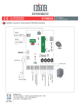
4. STANDARD INSTALLATION
Ref. Code Description
1 GLOBE7
GLOBE10
Motor + control panel
2 GLOBEL1
GLOBELV1
GLOBESI
Extension set for chain automation
Extension set for belt automation
Intermediate guide support
3 LAMPH Flashing light
4 ASB1
ASB2
GLOBESB
Kit for the external release cord with lock
Cord blocking device (2000 mm)
Cord blocking device (5000 mm)
5 GOL4 Radio
6 XEL2
LAB4
LAB4S
Photocells
7 Safety edge
8 BATK1 Buffer battery kit
A Connect the power supply to an approved omnipolar switch with an opening distance
of the contacts of at least 3mm (not supplied).
The connection to the mains must be made via an independent channel, separated
from the connections to command and safety devices.
i
NOTE: the given operating and performance features can only be guaranteed with the use of DITEC
accessories and safety devices.
A
5
7
2x1.5 mm²
RG58 + 2x1.5 mm²
4x0.5 mm²
4x0.5 mm²
6
1
2
4
3
8
6

8
IP1839EN • 2012-07-31
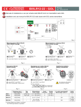
5. MAIN COMPONENTS
Ref. Code Description
1 24 V= motor with encoder
2 Fastening bracket
3 Slide carriage
4 Sliding guide
5 Fastening arm
6 Door section retention bracket
7 Control panel
2
1
4
3
5
6
7
30
2010
500

9
IP1839EN • 2012-07-31
6. ASSEMBLING BELT AND CHAIN
- Attach the belt or chain [A] to the transmission [B] and slide [C].
- Assemble the belt stop [D].
- Fasten the two ends of the belt [A] to the release pin [E] through the couplings [F] in the direction of the
pin, as shown in the gure.
- Fasten the two ends of the chain [A] to the release pin [E] through the couplings [F] in the direction of the
pin, as shown in the gure.
1
C
B
2
D
A
A
F
E
AE
3B
3A
F
FE
E
F

10
IP1839EN • 2012-07-31
7. ASSEMBLING THE AUTOMATION
- Insert the guide [B] into the non-bevelled side of the coupling [C] until it reaches the stop.
- Insert the guide [D] into the bevelled side of the coupling [C] until it reaches the stop.
- Insert the guide [D] into the non-bevelled side of the coupling [E] until it reaches the stop.
- Lay out the belt or chain [A] and insert it into the carriage side of assembled guide [B]+[C]+[D]+[E].
- Mount the guide [B] on the drive unit and pass the belt or chain [A] over the pulley [H], blocking it with the
pin [I]. Attach the guide [B] to the drive unit using the screw [J].
- Place the guide [F] over the coupling [E].
- Insert the transmission [G] correctly into the guide [F], raising the guide to facilitate insertion.
- Insert the guide [F] into the coupling [E].
- the coupling [E] towards the transmission [G] until its reaches the guide stop [F].
E
F
D
B B
C C
C
D
1 2 3
A
370
1066 1066
205400 370205400 370
1066
205
B D F
G
C E
A
H
I
B
J
NOTE: the correct direction for inserting the guide in shown in the gure.
i

11
IP1839EN • 2012-07-31
8. TENSIONING BELT AND CHAIN
- Assemble the transmission unit as indicated in the gure.
- To tension the chain or belt correctly, 1÷2 mm should be left between the spring retainer [A] and the stop
[B], so that the spring [C] can function properly.
WARNING: over-tensioning the chain or belt will prevent the automatic system from functioning properly.
1 2
A
B
C A
C
1÷2
B

12
IP1839EN • 2012-07-31
9. MECHANICAL INSTALLATION
- Select and mark the point where the guide will be mounted on the wall and ceiling.
- Leaving the control unit on the oor, mount the guide [A] on the wall using the transmission support bracket
[B].
- Insert the retention brackets [C] and lock them in place with the screws provided.
- Raise the control unit and bend the brackets as necessary (excess parts can be removed), then attach to
the ceiling.
A
B
C
10÷100
45°
min 680

13
IP1839EN • 2012-07-31
10. FASTENING THE ARM
- Mount the door section retention bracket [A] on the top of the door, using the reinforcement angle brackets
[B] provided, if necessary.
- Release the automation as shown on page 27. Bring the slide [C] to the closed door and attach the arm [D]
to the slide [C] so as to form approximately a 45° angle with the upright section of the door. If necessary
adjust the length of the arm [D] using the extension [E].
WARNING: in order to open particularly high sectional doors completely, the attachment point [F] can be
moved 20 mm to 100 mm inwards from the point where the door section retention bracket [A] is fastened,
inserting a shim [G] if necessary (not provided, max. 200 mm), so as to increase the slide stroke and use
all of the available guide.
An angle of approximately 45° should always be kept between the arm and upright section of the sectional door.
A
B
B
A
C
A
D
F
45°
C
45°
D
E
F
G
max
200
20÷100
A

14
IP1839EN • 2012-07-31
11. INSTALLATION OF THE END STOPS
- Insert the opening end stop [A] in the guide [B], as shown in the gure, and fasten it in place, where pre-
ferred.
- Insert the closing end stop [C] in the guide [B], as shown in the gure, and fasten it in place, where pre-
ferred.
DOOR TYPE
YEAR OF MANUF
A
CTURE
V
OL T
A
GE SUPPL
Y
SERIAL
NUMBER
2
1
12. INSTALLATION OF THE MANUAL RELEASE
In order to facilitate the release and movement of the sectional door, position the cord release near the handle,
as shown in the gure.
AC B
L
L = max 2760
max 3820 [GLOBEL1-GLOBELV1]

15
IP1839EN • 2012-07-31
13. INSTALLATION OF THE GLOBEC ADAPTER FOR UP-AND-OVER DOORS
max 210
min 20
min 900

16
IP1839EN • 2012-07-31
14. INSTALLATION OF THE GLOBESI INTERMEDIATE SUPPORT
1
220
50
30 75
2
1
2

17
IP1839EN • 2012-07-31
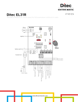
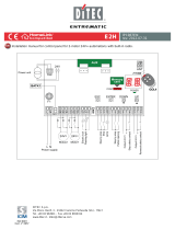
15. ELECTRICAL CONNECTIONS
The gure shows the main connections of the control panel 70R-71R.
-
+
Output 24 V= / max 0.3 A
Stop
Safety re-opening
Step-by-step
Lamp
Electric lock
Flashing light
TCR1
SIG
ON
OFF
123 4 5 6
PRG
SA
POWER
ALARM
1515 13 14 0 89
ENC
BATK1
Transformer
24V=
Motor
GOL4
COM
BIXMR2
M+
M
-
24 V~
AUX
ANT
F1
Power supply
SO
JR4
JR3
JR2
Courtesy
light
5
6
Black
Blue
GLOBE10
15
13
GLOBE10

18
IP1839EN • 2012-07-31
16. COMMANDS
Command Function Description
1
5 N.O. STEP-BY-STEP With DIP1=OFF, the closing of the contact activates opening
or closing operations in the following sequence: open-stop-
close-open.
Note: if automatic closing is enabled, the stop is not permanent
but lasts for a duration set by TC.
OPENING WITH
AUTOMATIC
CLOSING
With DIP1=ON and TC<MAX, the closing of the contact acti-
vates the opening operation.
OPENING WITHOUT
AUTOMATIC
CLOSING
With DIP1=ON and TC=MAX, the closing of the contact acti-
vates the opening operation.
Note: once the automation stops, the closing of the contact
performs the opposite operation to the one performed before
stop.
1
8 N.C. REVERSE
SAFETY CONTACT
The opening of the safety contact triggers a reversal of motion
(re-opening) during closing.
1
9 N.C. STOP The opening of the safety contact stops the current operation.
PRG
N.O. TRANSMITTERS
STORAGE AND
CANCELLATION
WARNING: the BIXMR2 storage module must be inserted.
Transmitter storage:
- press the PRG key (the SIG LED comes on),
- transmit the transmitter to be stored (the SIG LED ashes),
- wait 10 s to complete storage (the SIG LED goes out).
Transmitter cancellation:
- press the PRG key for 3 sec (the SIG LED ashes),
- press the PRG key for another 3 sec (the SIG LED ashes
quickly).
WARNING: make a jumper for all the N.C. contacts if not in use. The terminals with the same number
are equal.

19
IP1839EN • 2012-07-31
17. OUTPUTS AND ACCESSORIES
Output Value - Accessories Description
4901 23
+
-
24 V= / 0.3 A
Accessories power supply. Power supply output for external ac-
cessories, including automation status lamp.
0
14
LAMPH
24 V= / 25 W
Flashing light. Activated during opening and closing operations.
24 V= / 25 W
Internal courtesy light. A courtesy light that turns on for 180 se-
conds with every opening (total or partial), step-by-step and closing
command can be connected.
1
13
24 V= / 3 W
Automation status lamp (proportional).
The light switches off when the automation is closed; the light
switches on when the automation is open; the light ashes with a
variable frequency while the automation is operating.
0
15 24 V= / 1.2 A max
Electric lock. With DIP5=ON, on with the door closed.
0
15 12 V / 15 W
Electric lock. With a 12V electric lock, connect the supplied 8.2 Ω /
5 W resistance in series.
With DIP5=ON, on with the door closed.
ANT
BIXAL
Connect the supplied antenna wire (173 mm), or alternatively the
BIXAL antenna, using a coaxial cable, type RG58.
AUX
The control panel has one housing for plug-in cards such as a radio
receiver type, magnetic loops, etc.
Plug-in card operating is selected using DIP1.
WARNING: the plug-in cards must be inserted and removed with
the power supply disconnected.
COM
BIXMR2
The BIXMR2 storage module allows remote controls to be stored.
If the control panel is replaced, the BIXMR2 storage module being
used can be inserted in the new control panel.
WARNING: the storage module must be inserted and removed with
the power supply disconnected.
BAT
BATK1
2 x 12 V / 2 Ah
Battery operating. The batteries are kept charged when the power
supply is on. If the power supply is off, the control panel is powered
by the batteries until power is re-established or until the battery
voltage drops below the safety threshold. If this occurs, the control
panel turns off.
WARNING: the batteries must always be connected to the control
panel for charging. Periodically check the efciency of the batteries.
NOTE: the operating temperature of the rechargeable batteries is
approximately +5°C/+40°C.
GLOBE10

20
IP1839EN • 2012-07-31
18. ADJUSTMENTS
Description OFF ON
DIP1 Command 1-5 operation.
NOTE: it also sets operating mode of the
plugin cards connected on AUX.
Step-by-step. Opening.
DIP2 Direction selection. Opening towards gearmotor. Closing towards gearmotor.
DIP3 Disengagement on the closing stop
with JR2=ON.
2 mm. 0,5 mm.
NOTE: use of the selection
is recommended to prevent
the sectional door from clo-
sing incompletely.
Disengagement on the closing stop
with JR2=OFF.
5 mm. 5 mm.
DIP4 Automation status at power on.
Indicates how the control panel considers
automation when powered up.
Open. Closed.
NOTE: if the automatic clo-
sing function is not used,
preferably set DIP4=ON.
DIP5 Electric lock release.
Before opening from closed door, a thrust
is included in closing to facilitate electric
lock release.
Disabled. Enabled.
DIP6 3 seconds preashing. Disabled during opening.
Enabled only with automatic
closing with TC>3 s.
Enabled for both opening
and closing.
GLOBE10
Description OFF ON
SO Reversal safety switch function. With the automation blocked,
if the contact 1-8 is open, it
is possible to activate the
opening operation.
With the automation blocked,
if the contact 1-8 is open,
any operation is impossible.
JR2 Automation type selection. Up and over door with
counterweights.
Sectional door or up and
over door with springs.
JR3 Selection of maximum working force
limit.
Normal closing force. Reduced closing force.
JR4 Incorporated radio receiver. Disabled. Enabled.
Trimmer Description
R1
minmax
Force adjustment.
The control panel is equipped with a safety system that stops motion if an obstacle is
encountered during an opening operation and inverts the movement during a closing
operation.
TC
0 s Disabled
120 s
Setting automatic closing time. From 0 to 120 s.
The counter starts when automation is opened and lasts for the entire duration set with
TC trimmer (100%).
Once a safety switch has been activated, the counter starts as soon as the safety
switch is released (for example, after passing through the photocells), and lasts for the
entire time set with TC trimmer (100%).
Note: after the activation of the stop command, once contact 1-9 has closed again,
automatic closing is only enabled after a total, partial or step-by-step opening com-
mand.
/