VDS Utile is an operator for sectional and counterweight garage doors. It ensures compliance with norms UNI EN 12453, EN 12445 and the CE mark. VDS Utile's features include:
- Emergency release: Allows for manual operation of the door in case of power failure.
- Adjustable opening force: Can be adjusted to accommodate different door weights (up to 100Kg).
- Built-in limit switch: Automatically stops the door at the desired open and close positions.
- Easy installation: Comes with a mounting accessory kit and detailed instructions.
- Wide compatibility: Can be used with both sectional and counterweight garage doors.

UTILE
OPERATOR FOR SECTIONAL
AND COUNTERWEIGHT
GARAGE DOORS
WARNING!! Before installing, thoroughly read this manual that is an integral
part of the pack
The CE mark conforms to European directive
EEC 89/336 + 92/31 + 93/68 D.L. 04/12/1992 N. 476.
Our products if installed by qualified personnel capable to evaluate risks,
comply with norms UNI EN 12453, EN 12445

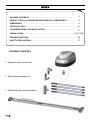
PACKING CONTENTS ............................................................................
2
VIEW OF TYPICAL AUTOMATION AND NAMES OF COMPONENTS ............
3
DIMENSIONS .........................................................................................
4
TECHNICAL DATA..................................................................................
4
CONSIDERATIONS FOR INSTALLATION..................................................
4
INSTALLATION......................................................................................
5-6-7-8-9
TROUBLESHOOTING..............................................................................
10
SAFETY PRECAUTIONS ........................................................................
11
1- Operator with control unit
1- Mounting accessory kit
1- Guide with pre-mounted chain
PACKING CONTENTS

D
E
F
C
G
H
B
I
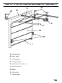
VIEW OF TYPICAL AUTOMATION AND NAMES OF COMPONENTS
A
A = Flashing light
B = Door frame
C = Pulling guide
D = Fixing brackets
E = Operator with control unit
F = Manual release
G = Door
H = Photocells
I = Rubber edge

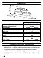
DIMENSIONS
Maximum height counterweight door
3000mm
Maximum height sectional door
2700mm
Door max width
3000mm
4500mm
Supply
230Vac
Motor power supply
24Vdc
Motor RPM
220
Emergency release Mechanical internal-external
Working temperature
-20° C / +55° C
Weight
4 Kg
Protection rating
IP 30
Opening time
22 sec
Force of thrust
700 N
1000 N
Motor current input
0,7 A
1,2 A
100Kg70Kg
TECHNICAL DATA
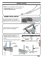
CONSIDERATIONS FOR INSTALLATION
150 mm
330 mm
230 mm
Ÿ
The installation and testing operations must be performed solely by qualified
personnel in order to guarantee the proper and safe operation of the automatic gate.
Ÿ The company declines any responsibility for damage caused by incorrect
installations due to incompetence and/or negligence.
Ÿ Before the installation of the automation, check that the door is fully functional
and balanced.

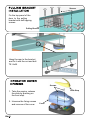
INSTALLATION
NOTE: For the installation of the operator on
counterweight doors you must use the
CURVED ARM (optional)
Fix the front support of the guide on
the door frame or on the wall
depending on the measurement taken.
Insert and lock the preassembled
guide into the front support
Bend the brackets according to the
measure A.This measure is
obtained leveling the guide with the
ceiling
Fix the brackets on the guide support
and motor support
A
Ceiling
Brackets
Guide
Guide
support
Motor
support
Brackets
Brackets

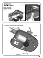
Fix the top panel of the
door to the pulling
bracket with self tapping
screws
Hang the arm to the bracket
and fix it with the nut and bolt
TE 8x25
1. Take the engine, release
the slide by pushing on
the front stop.
2. Unscrew the fixing screws
and remove of the cover.
Slide Stop
Cover
Screws
Screws
TE Bolt
Nut
Pulling Bracket

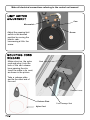
Insert the motor
bringing the shaft
into the seat of the
gear
Fix the motor with three self tapping screws
Screw
Screw
Screw
Gear Seat
Motor Shaft

Adjust the opening limit
switch in the desired
position by moving the
plastic cam,
unscrewing a little the
screw
Make all electrical connections referring to the control unit manual
Cam
Screw
Microswitch
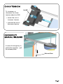
Make a knot on the nylon
cord and plug it into the
hole of the cart release
lever passing the site.
Insert the cable in its seat,
as shown in the picture
Take a release plate
and tie the other end of
the cord
Release Plate
Nylon Cord
Release Lever
Cord Passage Seat
Cart

To increase or
decrease the chain
tension adjust nut M8
Ÿ screw the nut to
increase tension
Ÿ unscrew the nut to
decrease tension
Nut M8
In case of emergency to
unlock the operator pull
the release plate
Release Plate

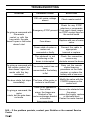
TROUBLESHOOTING
PROBLEM PROBABLE CAUSE
SOLUTION
On giving a command with
the remote
control or with the
key-switch, the gate
doesn’t open or the motor
doesn’t start
230 volt mains voltage
absent
Check master switch
Emergency STOP present
Check for any STOP
selectors or commands.
If not used, check jumper
on STOP contact input on
the control board
Fuse blown
Replace with one of same
value.
Power cable of motor or
motors not
connected or faulty.
Connect the cable to
appropriate
terminal or replace.
The photocell is not
functioning or the
beam is interrupted
Check the connection,
remove any
obstacle across the beam
On giving a command with
the remote control, the
door doesn’t open but
works with the key
command
The remote control has not
been
memorised or the battery
is flat
Carry out the remote
control learning
procedure on the radio
receiver or replace the
battery with a new one..
The door starts, but stops
immediately
The force of the motor or
motors is insufficient
Modify the value with the
FORCE trimmer on the
control unit
On giving a command, the
motor
starts, but the gate does
not move
There is an obstacle in
front of the
wings, the hinges are
blocked or the
motor anchorage bracket
or brackets
have come loose
Remove the obstacle from
the wings,
restore the hinges, replace
or lubricate them.
Fasten the motor bracket
N.B. - If the problem persists, contact your Retailer or the nearest Service
Centre

SAFETY PRECAUTIONS
These warnings are an essential, integral part of the product and must be given to the user. They
provide important indications on the installation, use and maintenance and must be read carefully.
This form must be preserved and passed on to subsequent users of the system. The incorrect
installation or improper use of the product may be dangerous.
INSTALLATION INSTRUCTIONS
• The installation must be performed by professionally skilled personnel and in compliance with
current local, state, national and European legislation.
• Before beginning the installation, check the integrity of the product.
• The laying of cables, electrical connections and adjustments must be workmanlike performed.
• The packing materials (cardboard, plastic, polystyrene, etc.) are a potential hazard and should
be disposed of correctly and not left within reach of children.
• Do not install the product in potentially explosive environments or environments disturbed by
electromagnetic fields. The presence of inflammable gases or fumes is a grave danger to
safety.
• Set up a safety device for overvoltage, a disconnecting and/or differential switch suitable for
the product and conforming to current standards.
• The manufacturer declines any and all responsibility for product integrity, safety and operation
in the event incompatible devices and/or components are installed.
• Solely original spare parts should be used for repairs and replacements.
• The installer must provide all the information relating to the operation, maintenance and use of
the individual parts, components and system as a whole.
WARNINGS FOR THE USER
• Read the instructions and enclosed documentation carefully.
• The product must be used for the express purpose for which it was designed. Any other use is
considered improper and therefore hazardous. In addition, the information given in this
document and in the enclosed documentation may be subject to modifications without prior
notice. It is given as an indication only for product application. The company declines any
responsibility for the above.
• Keep products, devices, documentation and anything else provided out of reach of children.
In the event of maintenance, cleaning, breakdown or faulty operation of the product, cut off the
power and do not attempt to operate on the product. Contact solely the professionally skilled
personnel responsible for these operations. Failure to adhere to the above indications may be
dangerous.

Via Circolare p.i.p. N° 10
65010 Santa Teresa di Spoltore (PE) - ITALY
Tel. +39 085 4971946 - FAX +39 085 4973849
www.vdsconsorzio.it - [email protected]
Rev. 0-12/11 Ing
The data and images are for guidance only
VDS reserves the right to change at any time characteristics of the products described in
its sole discretion, without notice.
-
 1
1
-
 2
2
-
 3
3
-
 4
4
-
 5
5
-
 6
6
-
 7
7
-
 8
8
-
 9
9
-
 10
10
-
 11
11
-
 12
12


VDS Utile is an operator for sectional and counterweight garage doors. It ensures compliance with norms UNI EN 12453, EN 12445 and the CE mark. VDS Utile's features include:
- Emergency release: Allows for manual operation of the door in case of power failure.
- Adjustable opening force: Can be adjusted to accommodate different door weights (up to 100Kg).
- Built-in limit switch: Automatically stops the door at the desired open and close positions.
- Easy installation: Comes with a mounting accessory kit and detailed instructions.
- Wide compatibility: Can be used with both sectional and counterweight garage doors.
Ask a question and I''ll find the answer in the document
Finding information in a document is now easier with AI
Related papers
Other documents
-
CAME V900E Specification
-
-
-
-
 DITEC CROSS 18-19 Owner's manual
-
 Mhouse WU2S Owner's manual
-
BFT TIR60, TIR120 Owner's manual
-
Chamberlain LiftMaster BAR Owner's manual
-
-
Nice X-BAR Instructions And Warnings For Installation And Use

