
AC Power
For Business-Critical Continuity™
Liebert
®
PSI
™
User Manual–750/1000/1500/2200/3000, 230VAC


i
TABLE OF CONTENTS
IMPORTANT SAFETY INSTRUCTIONS . . . . . . . . . . . . . . . . . . . . . . . . . . . . . . . . . . . . . . . . . . . . . . . .1
GLOSSARY OF SYMBOLS . . . . . . . . . . . . . . . . . . . . . . . . . . . . . . . . . . . . . . . . . . . . . . . . . . . . . . . .3
1.0 I
NTRODUCTION . . . . . . . . . . . . . . . . . . . . . . . . . . . . . . . . . . . . . . . . . . . . . . . . . . . . . . . . . .4
2.0 W
HAT’S INCLUDED . . . . . . . . . . . . . . . . . . . . . . . . . . . . . . . . . . . . . . . . . . . . . . . . . . . . . . .5
3.0 INSTALLATION . . . . . . . . . . . . . . . . . . . . . . . . . . . . . . . . . . . . . . . . . . . . . . . . . . . . . . . . . .6
3.1 Preparation . . . . . . . . . . . . . . . . . . . . . . . . . . . . . . . . . . . . . . . . . . . . . . . . . . . . . . . . . . . . . . . . . 6
3.2 Tower UPS Installation . . . . . . . . . . . . . . . . . . . . . . . . . . . . . . . . . . . . . . . . . . . . . . . . . . . . . . . 7
3.3 Rack-Mount UPS Conversion and Installation . . . . . . . . . . . . . . . . . . . . . . . . . . . . . . . . . . . . 8
3.4 Orient Display for Installation . . . . . . . . . . . . . . . . . . . . . . . . . . . . . . . . . . . . . . . . . . . . . . . . . 9
3.5 Connect Input Power and Load . . . . . . . . . . . . . . . . . . . . . . . . . . . . . . . . . . . . . . . . . . . . . . . . . 9
3.6 Connect Network Surge protection . . . . . . . . . . . . . . . . . . . . . . . . . . . . . . . . . . . . . . . . . . . . . 10
3.7 Connect Communication Interface . . . . . . . . . . . . . . . . . . . . . . . . . . . . . . . . . . . . . . . . . . . . . 10
3.8 Set Up Liebert MultiLink software . . . . . . . . . . . . . . . . . . . . . . . . . . . . . . . . . . . . . . . . . . . . . 11
3.9 EPO Switch. . . . . . . . . . . . . . . . . . . . . . . . . . . . . . . . . . . . . . . . . . . . . . . . . . . . . . . . . . . . . . . . 11
4.0 CONTROLS AND INDICATORS. . . . . . . . . . . . . . . . . . . . . . . . . . . . . . . . . . . . . . . . . . . . . . .12
4.1 Control Buttons . . . . . . . . . . . . . . . . . . . . . . . . . . . . . . . . . . . . . . . . . . . . . . . . . . . . . . . . . . . . 13
4.1.1 On/Alarm Silence/Manual Self-Diagnostic Test . . . . . . . . . . . . . . . . . . . . . . . . . . . . . . . . . . . . 13
4.1.2 Off Button . . . . . . . . . . . . . . . . . . . . . . . . . . . . . . . . . . . . . . . . . . . . . . . . . . . . . . . . . . . . . . . . . . 13
4.2 Status Indicators . . . . . . . . . . . . . . . . . . . . . . . . . . . . . . . . . . . . . . . . . . . . . . . . . . . . . . . . . . . 13
4.2.1 Status Change Button . . . . . . . . . . . . . . . . . . . . . . . . . . . . . . . . . . . . . . . . . . . . . . . . . . . . . . . . 13
4.2.2 Load Level Indicator. . . . . . . . . . . . . . . . . . . . . . . . . . . . . . . . . . . . . . . . . . . . . . . . . . . . . . . . . . 13
4.2.3 Battery Level Indicator . . . . . . . . . . . . . . . . . . . . . . . . . . . . . . . . . . . . . . . . . . . . . . . . . . . . . . . 14
4.2.4 UPS Status Indicators . . . . . . . . . . . . . . . . . . . . . . . . . . . . . . . . . . . . . . . . . . . . . . . . . . . . . . . . 14
5.0 OPERATIONAL MODES . . . . . . . . . . . . . . . . . . . . . . . . . . . . . . . . . . . . . . . . . . . . . . . . . . .15
5.1 Normal Mode . . . . . . . . . . . . . . . . . . . . . . . . . . . . . . . . . . . . . . . . . . . . . . . . . . . . . . . . . . . . . . 15
5.2 Buck/Boost Mode . . . . . . . . . . . . . . . . . . . . . . . . . . . . . . . . . . . . . . . . . . . . . . . . . . . . . . . . . . . 15
5.3 Battery Mode . . . . . . . . . . . . . . . . . . . . . . . . . . . . . . . . . . . . . . . . . . . . . . . . . . . . . . . . . . . . . . 15
5.4 Battery Recharge Operation . . . . . . . . . . . . . . . . . . . . . . . . . . . . . . . . . . . . . . . . . . . . . . . . . . 15
6.0 COMMUNICATION . . . . . . . . . . . . . . . . . . . . . . . . . . . . . . . . . . . . . . . . . . . . . . . . . . . . . . .16
6.1 DB-9 Connector . . . . . . . . . . . . . . . . . . . . . . . . . . . . . . . . . . . . . . . . . . . . . . . . . . . . . . . . . . . . 16
6.2 Remote Shutdown Via the DB-9 Connector . . . . . . . . . . . . . . . . . . . . . . . . . . . . . . . . . . . . . . 16
6.2.1 Any Mode Shutdown Via Pins 5 & 6 . . . . . . . . . . . . . . . . . . . . . . . . . . . . . . . . . . . . . . . . . . . . . 16
6.2.2 Battery Mode Shutdown Via Pins 4 & 5 . . . . . . . . . . . . . . . . . . . . . . . . . . . . . . . . . . . . . . . . . . 16
6.3 RJ-45 Data Line Protection Connectors . . . . . . . . . . . . . . . . . . . . . . . . . . . . . . . . . . . . . . . . . 16
6.4 UPS Communications . . . . . . . . . . . . . . . . . . . . . . . . . . . . . . . . . . . . . . . . . . . . . . . . . . . . . . . 17
6.5 UPS Inverter/Transfer Voltage Configurations . . . . . . . . . . . . . . . . . . . . . . . . . . . . . . . . . . . 17

ii
7.0 BATTERY MAINTENANCE. . . . . . . . . . . . . . . . . . . . . . . . . . . . . . . . . . . . . . . . . . . . . . . . . .18
7.1 Battery Charging, Storage. . . . . . . . . . . . . . . . . . . . . . . . . . . . . . . . . . . . . . . . . . . . . . . . . . . . 18
7.2 Internal Battery Replacement Procedure . . . . . . . . . . . . . . . . . . . . . . . . . . . . . . . . . . . . . . . . 18
8.0 SPECIFICATIONS . . . . . . . . . . . . . . . . . . . . . . . . . . . . . . . . . . . . . . . . . . . . . . . . . . . . . . . .19
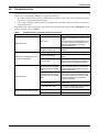
9.0 TROUBLESHOOTING . . . . . . . . . . . . . . . . . . . . . . . . . . . . . . . . . . . . . . . . . . . . . . . . . . . . .21
FIGURES
Figure 1 Front view of UPS . . . . . . . . . . . . . . . . . . . . . . . . . . . . . . . . . . . . . . . . . . . . . . . . . . . . . . . . . . . . . . . . 4
Figure 2 750, 1000 and 1500—rear view . . . . . . . . . . . . . . . . . . . . . . . . . . . . . . . . . . . . . . . . . . . . . . . . . . . . . 4
Figure 3 2200 and 3000—rear view . . . . . . . . . . . . . . . . . . . . . . . . . . . . . . . . . . . . . . . . . . . . . . . . . . . . . . . . . 4
Figure 4 Accessories. . . . . . . . . . . . . . . . . . . . . . . . . . . . . . . . . . . . . . . . . . . . . . . . . . . . . . . . . . . . . . . . . . . . . . 5
Figure 5 Placing the Liebert PSI. . . . . . . . . . . . . . . . . . . . . . . . . . . . . . . . . . . . . . . . . . . . . . . . . . . . . . . . . . . . 6
Figure 6 Tower configuration—attach Tower Stand . . . . . . . . . . . . . . . . . . . . . . . . . . . . . . . . . . . . . . . . . . . . 7
Figure 7 Convert the Liebert PSI for rack installation . . . . . . . . . . . . . . . . . . . . . . . . . . . . . . . . . . . . . . . . . . 8
Figure 8 Orienting the UPS display . . . . . . . . . . . . . . . . . . . . . . . . . . . . . . . . . . . . . . . . . . . . . . . . . . . . . . . . . 9
Figure 9 Connect mains power and load. . . . . . . . . . . . . . . . . . . . . . . . . . . . . . . . . . . . . . . . . . . . . . . . . . . . . . 9
Figure 10 Connect network surge protection . . . . . . . . . . . . . . . . . . . . . . . . . . . . . . . . . . . . . . . . . . . . . . . . . . 10
Figure 11 Connect communication interface . . . . . . . . . . . . . . . . . . . . . . . . . . . . . . . . . . . . . . . . . . . . . . . . . . 10
Figure 12 EPO connection for normally open operation . . . . . . . . . . . . . . . . . . . . . . . . . . . . . . . . . . . . . . . . . 11
Figure 13 Display and status indicators. . . . . . . . . . . . . . . . . . . . . . . . . . . . . . . . . . . . . . . . . . . . . . . . . . . . . . 12
Figure 14 DIP switch settings for 230V system . . . . . . . . . . . . . . . . . . . . . . . . . . . . . . . . . . . . . . . . . . . . . . . . 17
Figure 15 Battery replacement . . . . . . . . . . . . . . . . . . . . . . . . . . . . . . . . . . . . . . . . . . . . . . . . . . . . . . . . . . . . . 18
TABLES
Table 1 Display and status indicators function, legend . . . . . . . . . . . . . . . . . . . . . . . . . . . . . . . . . . . . . . . . 12
Table 2 Status indicators—color, illumination mode . . . . . . . . . . . . . . . . . . . . . . . . . . . . . . . . . . . . . . . . . . 14
Table 3 DB-9 pin assignment . . . . . . . . . . . . . . . . . . . . . . . . . . . . . . . . . . . . . . . . . . . . . . . . . . . . . . . . . . . . 16
Table 4 Voltage configurations . . . . . . . . . . . . . . . . . . . . . . . . . . . . . . . . . . . . . . . . . . . . . . . . . . . . . . . . . . . 17
Table 5 Liebert PSI specifications . . . . . . . . . . . . . . . . . . . . . . . . . . . . . . . . . . . . . . . . . . . . . . . . . . . . . . . . . 19
Table 6 Load Autonomy - Liebert PSI 750VA-3000VA . . . . . . . . . . . . . . . . . . . . . . . . . . . . . . . . . . . . . . . . 20
Table 7 Troubleshooting—problems, causes and solutions . . . . . . . . . . . . . . . . . . . . . . . . . . . . . . . . . . . . . 21

1
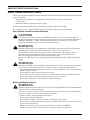
IMPORTANT SAFETY INSTRUCTIONS
SAVE THESE INSTRUCTIONS
This manual contains important instructions that should be followed during installation and mainte-
nance of the UPS.
• Intended for installation in a temperature-controlled, indoor area free of conductive
contaminants.
• Maximum ambient temperature 40°C (104°F).
Read this manual thoroughly before attempting to install or operate this UPS.
The equipment can be installed and operated by individuals without previous training.
Size of Branch Circuit Overcurrent Protection
Battery Handling Precautions
!
CAUTION
To reduce the risk of fire, connect PS3000RT3-230 models only to a circuit provided with
30 amperes maximum branch circuit overcurrent protection in accordance with IEC60950-1,
VDE0805, EN62040-1-1. Other Liebert PSI models must be connected to a circuit with
20 amperes maximum branch circuit overcurrent protection.
!
WARNING
Install the UPS indoors in a temperature- and humidity-controlled room, free of conductive
contaminants, moisture, flammable liquids, gases and corrosive substances.
Some components are live, even when AC power is disconnected. For service, contact a
properly trained and qualified technician. Do not remove the cover; the UPS has no
user-serviceable parts inside except the internal battery pack.
Operate the UPS only from a properly grounded (earthed) 220-240 VAC, 50Hz or 60Hz AC
supply.
!
WARNING
Although the UPS has been designed and manufactured to ensure personal safety, improper
use can result in electrical shock or fire. To ensure safety, observe the following rules:
• Turn Off and unplug the UPS before cleaning it. Clean the UPS with a dry cloth. Do not use
liquid or aerosol cleaners.
• Do not install or operate the UPS in or near water.
• Never block or insert any objects into the ventilation holes or other openings of the UPS.
Keep all vents free of dust accumulation that could restrict air flow.
• Do not place UPS power cord anywhere it might be damaged.
!
WARNING
Batteries should be replaced only by properly trained and qualified personnel knowledgeable
of batteries and required precautions.
A battery can present a risk of electrical shock and high short-circuit current. The following
precautions must be observed when working on batteries:
• Remove watches, rings and other metal objects.
• Use tools with insulated handles.
• Do not dispose battery or batteries in a fire. The battery may explode.
• Do not open or mutilate the battery or batteries. Released electrolyte is toxic. It may cause
injury to the skin and eyes.
• When replacing the battery, use the type of battery as is listed in Table 5.
• Handle, transport and recycle batteries in accordance with local regulations.

2
CONDITIONS OF USE—The mains supply socket must be within 1.8m (6ft.) of the UPS and be eas-
ily accessed.
This UPS provides conditioned power to connected equipment. It is designed for commercial use only.
It is not intended for use with life-support and other designated “critical” devices. Maximum load
must not exceed that shown on the UPS rating label. If uncertain, consult your local dealer, local
Emerson Network Power representative or Channel Support Applications.
The Liebert PSI
™
750, 1000 and 1500 models are not supplied with an input power cable for connec-
tion to the mains supply socket. Use the input mains supply power cable from your data processing
equipment to connect the UPS to the mains supply.
For the Liebert PSI 2200 and 3000 models, use the supplied 16A-rated input mains supply cables. For
UK supply systems, consult a properly trained and qualified electrician to connect the lead supplied
for the 2200 and 3000 models to the mains supply.
The UPS and connected load total earth leakage current must not exceed 3.5mA. If the connected load
earth leakage current is likely to exceed 2.5mA or if you are unsure, then convert the input cable
attachment to either a fixed wiring installation or an industrial plug/socket (e.g., CEE 17 connector).
This alteration should be carried out by a properly trained and qualified electrical engineer who is
conversant with local electrical codes and regulations.
When installing the UPS or making input and output connections, comply with all relevant safety
codes and standards (e.g. IEC60950-1, VDE0805, EN62040-1-1).
The batteries inside the UPS use components that are dangerous for the environment, such as elec-
tronic cards and other electronic components. Any component that is removed must be taken to spe-
cialized collection and disposal centers. If this unit must be dismantled, this must be done by special-
ized personnel who are properly trained and qualified. The unit must be taken to a center specialized
in collection and disposal of dangerous substances.
Placing magnetic storage media on top of the UPS may result in data corruption.
ELECTROMAGNETIC COMPATIBILITY—The Liebert PSI series complies with the require-
ments of EMC Directive 89/336/EEC and the published technical standards. Continued compliance
requires installation in accordance with these instructions and use of Emerson Network Power-
approved accessories only.
When using the communication features on this UPS, ensure the cabling connected to the DB-9 or
UPS communications ports are kept separated from the power leads to the UPS input and output.
NOTICE
Do not connect equipment that could overload the UPS or demand half-wave rectification
from the UPS, for example: electric drills, vacuum cleaners, laserjet/inkjet printers, hair
dryers, overhead projectors.
Battery service should be performed or supervised by personnel knowledgeable about batteries and
required precautions.
When replacing batteries, replace with the same type and number of batteries or battery packs.
!
CAUTION
Do not dispose of batteries in a fire. The batteries may explode.
!
CAUTION
Do not open or mutilate batteries. Released electrolyte is harmful to the skin and eyes. It may
be toxic.

3
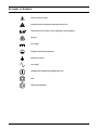
GLOSSARY OF SYMBOLS
.
Risk of electrical shock
Indicates caution followed by important instructions
Indicates the unit contains a valve-regulated, lead-acid battery
Recycle
DC voltage
Equipment grounding conductor
Bonded to ground
AC voltage
ON/Alarm Silence/Manual Self-Diagnostic Test
OFF
Status Change Button
!

Introduction
4
1.0 INTRODUCTION
The Liebert PSI is a 2U, line-interactive UPS that may be installed in a rack or used as a tower UPS.
Status indicators on the front of the Liebert PSI display load level, battery level, buck/boost, site-wir-
ing fault, overload, battery status and UPS operation. Controls include a combination On/Alarm
Silence/Manual Self-Diagnostic Test button, an Off button and a Status Change button.
The Liebert PSI has USB, DB-9 (contact closure) and Liebert IntelliSlot
®
ports. The DB-9 and USB
ports provide detailed operating information including voltages, currents, and alarm status to the
host system when used in conjunction with Liebert MultiLink
™
software.
The Liebert PSI is compliant with the Restriction of Hazardous Substances Directive (ROHS), prohib-
iting use of six hazardous materials manufacturing of electronics, including lead-free solder.
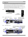
Figure 1 Front view of UPS
Figure 2 750, 1000 and 1500—rear view
Figure 3 2200 and 3000—rear view
Liebert PSI
rack-mount configuration
Display rotates for use as tower
Liebert PSI
tower configuration
Display rotates for use in rack
EPO
VOLTAGE=220V
VOLTAGE=230V
VOLTAGE=240V
21
FUNCTION
Voltage Configuration
DIP Switch
RJ-45 Data Line
Connectors
750: 7A Input Circuit Breaker
1000: 8A Input Circuit Breaker
1500: 10A Input Circuit Breaker
IEC-320-C14
Input Socket
Liebert
IntelliSlot Port
USB
Port
DB-9 Port
(Contact
Closure)
EPO
IEC-320-C13
Output Sockets
EPO
VOLTAGE=220V
VOLTAGE=230V
VOLTAGE=240V
2 1
FUNCTION
2200: 15A Input Circuit Breaker
3000: 20A Input Circuit Breaker
10A Output Circuit Breaker for
Four Output Sockets on Left
IEC-320-C20
Input Socket
IEC-320-C19
Output Socket
10A Output Circuit
Breaker for Four
Output Sockets
on Right
Voltage Configuration
DIP Switch
Liebert
IntelliSlot Port
USB
Port
DB-9 Port
(Contact
Closure)
EPO
IEC-320-C13
Output Sockets
RJ-45 Data Line
Connectors

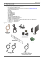
What’s Included
5
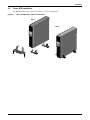
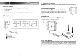
2.0 WHAT’S INCLUDED
The Liebert PSI is shipped with the following items:
• Multi-Language User Manual on CD
• Liebert MultiLink Software and User Manual, downloadable at multilink.liebert.com
• Contact Closure (ML9P9S) Cable
• USB Cable
• Tower Stand
• Mounting Hardware
• Rack-Mount Handles
• Fixed Mounting Rails
•EPO Connector
• Input Power Cord, 2200/3000 only: 2
• IEC Output Cable, 750/1000/1500 only: 2
• IEC Output Cable, 2200/3000 only: 3
• (1) Schuko to IEC-320-C19 and (1) UK plug to IEC-320-C19 input cord, 2200/3000 only
• (2) IEC-320-C13, 750/1000/1500 only
• (3) IEC-320-C13, 2200/3000 only
Figure 4 Accessories
EPO
Connector
Rack-Mount
Handles
Fixed
Mounting Rails
Mounting Hardware
(Screws & Washers)
USB Cable
1.8 m (6 ft)
Tower Stand
Contact Closure
(ML9P9S) Cable
1.8 m (6 ft)
Input Power Cables
(2 with 2200 and 3000
models)
Output Power Cable
(2 with 750, 1000 and 1500 models)
(3 with 2200 and 3000 models)

Installation
6
3.0 INSTALLATION
3.1 Preparation
Inspect the UPS for freight damage. Report any damage to the carrier and your local dealer or Emer-
son representative.
The Liebert PSI may be installed in either a tower or rack configuration. Determine the method that
suits the application and proceed.
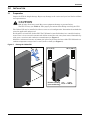
Decide where to install the Liebert PSI. The UPS must be installed indoors in a controlled environ-
ment. Place it in an area with unrestricted airflow around the unit, away from water, flammable liq-
uids, gases, corrosives and conductive contaminants (see Figure 5).
Maintain a minimum clearance of 305mm (12 inches) in the front and rear of the UPS. Maintain an
ambient temperature range of 0°C to 40°C (32°F to 104°F) (see Figure 5).
Figure 5 Placing the Liebert PSI
!
CAUTION
Risk of injury from heavy unit. May cause equipment damage or personal injury.
The UPS is heavy (see Table 5). Take proper precautions when lifting or moving the UPS.
0°C (32°F)
Relative humidity
(non-condensing)
40°C (104°F)
0% ~ 90%
305mm/12inch
AIR
AIR
AIR


Installation
8
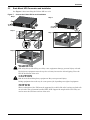
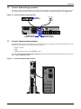
3.3 Rack-Mount UPS Conversion and Installation
See Figure 7 when installing the Liebert PSI in a rack.
Figure 7 Convert the Liebert PSI for rack installation
NOTICE
When rack-mounted, the UPS must be supported by a shelf, slide rails, brackets or fixed rails
on each side. The rack-mount handles WILL NOT support the weight of the UPS. They are
used to move the UPS into and out of the rack.
!
WARNING
Risk of top-heavy unit falling over. May cause equipment damage, personal injury or death.
Placing heavy equipment near the top of a rack may increase the risk of tipping. Place the
UPS in the bottom of the rack.
!
CAUTION
Risk of strain from lifting heavy equipment. May cause personal injury.
Lifting equipment into rack may be a two-person job, depending on weight of equipment.
L
o
a
d
L
e
v
e
l
B
a
t
t
e
r
y
L
e
v
e
l
L
o
a
d
L
e
v
e
l
B
a
t
t
e
r
y
L
e
v
e
l
L
o
a
d
L
e
v
e
l
B
a
t
t
e
r
y
L
e
v
e
l
L
o
a
d
L
e
v
e
l
B
a
t
t
e
r
y
L
e
v
e
l
Step 1
Step 2
Step 3
Step 4
Step 5

Installation
9
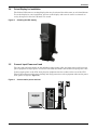
3.4 Orient Display for Installation
The Liebert PSI features a rotating display that may be oriented for either tower or rack installations.
To set the display for your installation, pull out on the display and rotate it until it is oriented cor-
rectly, then press it into the UPS until it is seated.
Figure 8 Orienting the UPS display
3.5 Connect Input Power and Load
The 750, 1000 and 1500 models do not include an input power cable; use input power cord from com-
puter equipment as input power cord of UPS. The 2200 and 3000 UPSs include an input power cable.
Connect input power to the UPS, then plug the equipment into the sockets on the rear of the UPS.
These UPS sockets provide battery backup and surge protection to the equipment when mains power
fails, spikes or sags (see Figure 9).
Figure 9 Connect mains power and load
EPO
VOLTAGE=220V
VOLTAGE=230V
VOLTAGE=240V
2 1
FUNCTION

Installation
10
3.6 Connect Network Surge protection
Connect a 10 base-T/100 network cable to the RJ-45 network surge protection IN jack on the rear of
the UPS. Connect from the OUT jack with network cabling to network equipment (see Figure 10).
Figure 10 Connect network surge protection
3.7 Connect Communication Interface
Determine what type of communication connection to use to manage the UPS. The Liebert PSI can be
monitored with any of these communication methods:
• Contact closure
•USB
• SNMP (requires optional IS-WEBRT3 card)
See 3.8 - Set Up Liebert MultiLink software for details and installation information. Also refer to
6.4 - UPS Communications.
Figure 11 Connect communication interface
EPO
VOLTAGE=220V
VOLTAGE=230V
VOLTAGE=240V
21
FUNCTION
Network Surge
Protection IN Jack
Network Surge
Protection OUT Jack
Network
Equipment
EPO
VOLTAGE=220V
VOLTAGE=230V
VOLTAGE=240V
21
FUNCTION

Installation
11
3.8 Set Up Liebert MultiLink software
To start using Liebert MultiLink (software and user manual available at multilink.liebert.com):
• Install the software.
See the Liebert MultiLink quick-start guide or user manual for installation instructions.
• Connect one end of the USB cable (supplied) to the USB port on the rear of the UPS. Connect the
other end to a USB port on the computer.
See the Liebert MultiLink user manual for operating instructions.
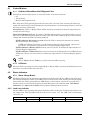
3.9 EPO Switch
The Liebert PSI is equipped with an Emergency Power Off (EPO) switch. The user must supply a
means of interfacing with the EPO circuit to allow disconnecting the UPS input feeder breaker to
interrupt all sources of power to the UPS and connected equipment to comply with national and local
wiring codes and regulations.
Figure 12 EPO connection for normally open operation
NOTE
Emerson recommends connecting the USB cable directly to the computer WITHOUT using a
USB hub.
1 = EPO+
2 = Ground
Short Pin 1 and Pin 2 to
enable the EPO function

Controls and Indicators
12
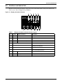
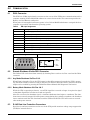
4.0 CONTROLS AND INDICATORS
Buttons on the front panel display control the Liebert PSI. Eight LEDs on the panel indicate the
UPS’s status. Refer to Figure 13 and Table 1.
Figure 13 Display and status indicators
Table 1 Display and status indicators function, legend
Item Name Status Indicators Description
1 LED 1 AVR Boost UPS Operation in AVR Boost Mode
2 LED 2 AVR Buck UPS Operation in AVR Buck Mode
3 LED 3 Battery Condition Battery Fault/Weak
4 LED 4 Load Indicator/Battery run time* Indicates load and battery run time
5 LED 5 Overload UPS Overload
1 to 5 Load/Battery Level Indicate Load/Battery Level
6 Status Change Button
Switches Display from Load Level Indicators
to Battery Level Indicators
7 OFF Button UPS Off
8ON Button
Turn on UPS, Manual Self-Diagnostic (Normal Mode),
Silence Alarm (Battery Mode)
9 LED 9 Normal Mode UPS Operation in Normal Mode
10 LED 10 Battery Mode UPS Operation in Battery Mode
11 LED 11 UPS Fault UPS Fault
* Site wiring fault LED is used only to indicate load and battery run time with 230V units
Load Level
Battery Level
12345
67891011

Controls and Indicators
13
4.1 Control Buttons
4.1.1 On/Alarm Silence/Manual Self-Diagnostic Test
This button controls output power to connected load(s). It has three functions:
•On
•Alarm Silence
• Manual Self-Diagnostic Test
ON—Start the UPS by pressing this button for more than 3 seconds, then releasing the button (an
alarm will sound briefly). If the ON button is pressed and mains is outside input parameters, the UPS
will start on battery (dark start).
Alarm Silence—Silence a Battery Mode audible alarm by pressing this button for longer than one
second, then releasing it.
Manual Self-Diagnostic Test—To initiate a Manual Self-Diagnostic, press this button for at least
three (3) seconds while operating from the mains. UPS will switch to Battery Mode to detect battery
voltage and whether the UPS is operating normally.
If LED indicates the battery is weak: Allow the UPS to recharge the batteries for 8 hours.
Retest the battery after recharge.
If LED still indicates the battery is weak after the battery has been retested, contact your
local dealer, local Emerson representative or Channel Support Applications.
If LED indicates a Battery Fault: Contact your local dealer, local Emerson representative or
Channel Support Applications.
If LED indicates a UPS Fault: Remove the load, retest the self-diagnostic test, if LED indicated
UPS Fault, Contact your local dealer, local Emerson representative or Channel Support Applica-
tions.
4.1.2 Off Button
When the UPS is operating in either Normal Mode or Battery Mode, pressing the Off button for more
than three seconds will shut down the UPS.
4.2 Status Indicators
4.2.1 Status Change Button
The Status Change button determines the information displayed by the five LEDs on the front panel.
The default information shown by the LEDs is the load level on the UPS. Pressing the Status Change
button while the UPS is On prompts the LED display to show battery capacity for 5 seconds. This
function assists in assessing the meaning of status indicators as described in 4.2.4 - UPS Status
Indicators. See Figure 13 and Table 1 for the Status Change button’s location.
4.2.2 Load Level Indicator
The five LEDs at the top of the front panel illuminate with a steady glow to indicate the load level on
the output of the UPS. The LEDs show the load level as a range, ± 5%. The LEDs’ load level meanings
and colors are:
NOTE
Refer to Figure 13 and Table 1 for details about the LEDs’ meaning.
LED 1 LED 2 LED 3 LED 4 LED 5
10-24% — Green 25-49% — Green 50-74% — Yellow 75-99% — Yellow 100% or greater — Red

Controls and Indicators
14
4.2.3 Battery Level Indicator
The five LEDs illuminate with a steady glow to indicate battery capacity. Battery capacity is shown
for five seconds after the Status Change button is pressed. The LEDs show the battery capacity as a
range, ± 5% The LEDs’ battery level meanings and colors are:
4.2.4 UPS Status Indicators
LEDs on the display panel illuminate with a steady glow or flash to indicate the UPS’s status:
Mains Mode—The Mains Mode indicator illuminates (LED 9) with a steady glow when mains power
is available and within the input specifications.
Battery Mode—The Battery Indicator illuminates (LED 10) with a steady glow when the UPS is
operating on battery.
AVR Boost, AVR Buck—When the UPS is in AVR Boost/Buck Mode, the LED display will indicate
the relative load level on the output of the UPS and will flash LED 1 (boost) or LED 2 (buck) to indi-
cate which mode the UPS is in.
Weak Battery—When the UPS battery voltage is low, the LED display will indicate the relative load
level on the output of the UPS and LED 3 will flash as a warning.
Overload—When UPS operates in overload status, the LED display will indicate the relative load
level on the output of the UPS and LED 5 will flash as a warning.
LED 1 LED 2 LED 3 LED 4 LED 5
100-76% — Green 75-51% — Green 50-26% — Yellow 25-11% — Yellow 10% or less — Red
Table 2 Status indicators—color, illumination mode
Status LED 1 LED 2 LED 3 LED 4 LED 5 LED 9 LED 10 LED 11
Normal Mode
Green
Steady
AVR Boost
Green
Flashes
Green
Steady
AVR Buck
Green
Flashes
Green
Steady
Battery Mode
(dark start)
Yellow
Steady
Weak Battery
Yellow
Flashes
Site-Wiring Fault
Not
applicable
Overload
Red
Flashes
Battery Fault
Shutdown
Yellow
Steady
Red
Steady
Overload
Shutdown
Red
Steady
Red
Steady
UPS Output
Abnormal
Shutdown
Yellow
Steady
Red
Steady

Operational Modes
15
5.0 OPERATIONAL MODES
5.1 Normal Mode
When the UPS is in Normal Mode, the Normal Mode Indicator illuminates green.
5.2 Buck/Boost Mode
The Automatic Voltage Regulator (AVR) circuitry compensates for fluctuations in mains power, such
as voltage surges and sags. The Liebert PSI compensates for these by raising the undervoltage (boost)
or lowering the overvoltage (buck). The AVR operates automatically and maintains the output voltage
to the connected equipment without utilizing the batteries.
5.3 Battery Mode
The UPS switches to Battery Mode in the event of an extreme input voltage/frequency condition or
mains failure.
When the UPS is in Battery Mode, the Battery Indicator illuminates amber and an alarm sounds at
2-second intervals. As capacity decreases, fewer indicators remain illuminated.
When a Low Battery condition occurs, the Battery Indicator flashes amber and an alarm sounds at
one-second intervals. For approximate battery run times, refer to Table 6.
5.4 Battery Recharge Operation
Once mains power is restored, the UPS resumes normal operation, and the Battery Charger begins
recharging the batteries.

Communication
16
6.0 COMMUNICATION
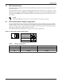
6.1 DB-9 Connector
The UPS has a DB-9 (9 pin female) connector on the rear to allow UPS status communications with a
computer running Liebert MultiLink software in contact closure mode. The connection provides On
Battery and Low Battery notification.
When power is interrupted and battery power is low, Liebert MultiLink software can signal the host
computer to gracefully shut down the operating system.
6.2 Remote Shutdown Via the DB-9 Connector
The Liebert PSI can be shut down remotely by shorting Pins 5 and 6 or via Pins 4 and 5 of the DB-9
connector.
6.2.1 Any Mode Shutdown Via Pins 5 & 6
When Pin 6 is shorted to Pin 5, the UPS output is shut Off no matter what mode the UPS is operat-
ing. The UPS cannot be started as long as the pins are shorted. When the short is removed, the UPS
output can be enabled by pressing the ON/Alarm Silence/Manual Self-Diagnostic Test button.
6.2.2 Battery Mode Shutdown Via Pins 4 & 5
While the UPS is operating on battery, a 5-12VDC signal for 2 seconds or longer is required to signal
a shutdown. Signals for less than 2 seconds are ignored.
After Pin 4 receives the shutdown signal, a 2-minute shutdown timer begins a countdown. The shut-
down timer cannot be stopped: If mains power returns during the 2-minute countdown, the shutdown
timer continues until the end of 2 minutes and the UPS turns Off. The UPS will restart 10 seconds
after mains power returns.
6.3 RJ-45 Data Line Protection Connectors
Data line (in and out) connectors on the rear of the UPS provide transient voltage surge suppression
(TVSS) for network devices.
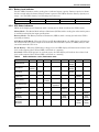
Table 3 DB-9 pin assignment
DB-9 Pin Assignment Description
1 Low Battery (open collector)
2 UPS TxD (not used)
3 UPS RxD (not used)
4 Remote Shutdown (5-12V); on-battery operation
5Common
6 Output Off, (short to Pin 5, non-latching); any mode operation
7 Low Battery (open emitter)
8 Mains Fail (open emitter)
9 Mains Fail (open collector)
Pin Assignment Collector to Emitter*
54321
6789
(-)
(+)
330 Ohms
Open
Collecto
r
Open
Emitter
Page is loading ...
Page is loading ...
Page is loading ...
Page is loading ...
Page is loading ...
Page is loading ...
Page is loading ...
Page is loading ...
-
 1
1
-
 2
2
-
 3
3
-
 4
4
-
 5
5
-
 6
6
-
 7
7
-
 8
8
-
 9
9
-
 10
10
-
 11
11
-
 12
12
-
 13
13
-
 14
14
-
 15
15
-
 16
16
-
 17
17
-
 18
18
-
 19
19
-
 20
20
-
 21
21
-
 22
22
-
 23
23
-
 24
24
-
 25
25
-
 26
26
-
 27
27
-
 28
28


Liebert PSI PS1000RT3-230 User manual
- Type
- User manual
- This manual is also suitable for
Ask a question and I''ll find the answer in the document
Finding information in a document is now easier with AI
Related papers
-
Liebert Liebert PSI 1000 User manual
-
Liebert UPS Systems PSI XR User manual
-
Emerson PowerSure PSI PS2200RT2-230E User manual
-
-
-
-
-
-
-
Other documents
-
Emerson Liebert PSI 1500VA User manual
-
SolaHD MultiLINK Owner's manual
-
Repotec RPT-2003DU Owner's manual
-
-
-
PowerWalker VI 2000 LCD Owner's manual
-
 PowerWalker DC SecureAdapter 12V Owner's manual
-
Eaton Powerware 5125 Replacement Manual
-
-
 OPTI-UPS GS1100B User manual

