Page is loading ...

Instruction manual
Istruzioni per l’uso
|
|
Notice d’emploi
Gebruiksaanwijzing
Bedienungsanleitung
EM 3732-II Command
EM 3732-II
EM 3731-II
Instruction manual

1
Contents
Contents
Important safety instructions .................................................................... 2
The product family ........................................................................................ 5
The frequency bank system ..................................................................... 6
Delivery includes ........................................................................................... 7
Product overview .......................................................................................... 8
Overview of the EM 3731-II/EM 3732-II/EM 3732-II COM receivers. 8
Overview of the displays .......................................................................... 9
Reception display ..................................................................................... 10
Status display ........................................................................................... 11
Putting the receiver into operation ........................................................ 13
Fitting the device feet ............................................................................. 13
Rack mounting .......................................................................................... 13
Connecting the antennas ....................................................................... 14
Daisy chaining receivers ......................................................................... 16
Connecting the receiver to the mains/
disconnecting the receiver from the mains ........................................ 17
Connecting the amplifier/mixing console ........................................... 17
Connecting devices with AES3 digital input ....................................... 18
Connecting an external word clock generator .................................... 18
Connecting the receivers to a PC via Ethernet ................................... 19
Using the receiver ....................................................................................... 20
Switching the receiver on/off ................................................................ 20
Connecting the headphones/adjusting the volume ......................... 20
Deactivating the lock mode ................................................................... 21
Synchronizing a transmitter with the receiver frequency ............... 21
Identifying receivers using the “Wireless Systems Manager”
software (identifying function) ............................................................ 22
Sorting channels using the “Wireless Systems Manager”
software ..................................................................................................... 23
Using the operating menu ........................................................................ 24
Overview of the operating menu .......................................................... 24
Working with the operating menu ....................................................... 25
Overview of the menus............................................................................ 26
Adjustment tips for the operating menu .............................................. 30
Cleaning the receiver .................................................................................. 41
Additional information .............................................................................. 42
HiDyn plus™ (HDP) noise reduction ..................................................... 42
Squelch ....................................................................................................... 42
Diversity reception ................................................................................... 43
If a problem occurs ...................................................................................... 44
Accessories ................................................................................................... 45
Specifications ............................................................................................... 46
Manufacturer Declarations ....................................................................... 48

Important safety instructions
2
Important safety instructions
1. Read these instructions.
2. Keep these instructions. Always include these instructions when
passing the receiver on to third parties.
3. Heed all warnings.
4. Follow all instructions.
5. Do not use this apparatus near water.
6. Clean only with a dry cloth.
7. Do not block any ventilation openings. Install in accordance with the
manufacturer’s instructions.
8. Do not install near any heat sources such as radiators, heat registers,
stoves, or other apparatus (including amplifiers) that produce heat.
9. Do not defeat the safety purpose of the polarized or grounding-type
plug. A polarized plug has two blades with one wider than the other. A
grounding type plug has two blades and a third grounding prong. The
wide blade or the third prong are provided for your safety. If the
provided plug does not fit into your outlet, consult an electrician for
replacement of the obsolete outlet.
10. Protect the power cord from being walked on or pinched, particularly
at plugs, convenience receptacles, and the point where they exit from
the apparatus.
11. Only use attachments/accessories specified by the manufacturer.
12. Use only with the cart, stand, tripod, bracket, or table specified by the
manufacturer, or sold with the apparatus. When a cart is used, use
caution when moving the cart/apparatus combination to avoid injury
from tip-over.
13. Unplug this apparatus during lightning storms or when unused for
long periods of time.
14. Refer all servicing to qualified service personnel.
Servicing is required when the apparatus has been damaged in any
way, such as power supply cord or plug is damaged, liquid has been
spilled or objects have fallen into the apparatus, when the apparatus
has been exposed to rain or moisture, does not operate normally, or
has been dropped.
15. To completely disconnect this apparatus from the AC mains,
disconnect the power supply cord plug from the AC receptacle.
16. WARNING: To reduce the risk of fire or electric shock, do not expose this
apparatus to rain or moisture.
17. Do not expose this equipment to dripping or splashing and ensure that
no objects filled with liquids, such as vases, are placed on the
equipment.
18. The mains plug of the power supply cord shall remain readily operable.

3
Important safety instructions
Hazard warnings on the rear of the receiver
The label shown on the left is attached to the rear of the receiver. The
symbols on this label have the following meaning:
This symbol is intended to alert the user to the presence of uninsulated
dangerous voltage within the receiver’s enclosure that may be of sufficient
magnitude to constitute risk of fire or electric shock.
This symbol is intended to alert the user to the risk of electric shock if the
receiver is opened. There are no user serviceable parts inside. Refer
servicing to qualified personnel only.
This symbol is intended to alert the user to the presence of important
operating and maintenance instructions in the literature accompanying
this receiver.
Overloading
Do not overload wall outlets and extension cords as this may result in fire
and electric shock.
Safety check
Upon completion of any service or repairs to this device, ask the service
technician to perform safety checks to determine that the device is in safe
operating order.
Danger of hearing damage due to high volumes
This is a professional receiver. Commercial use is subject to the rules and
regulations of the trade association responsible. Sennheiser, as the
manufacturer, is therefore obliged to expressly point out possible health
risks arising from use.
This receiver is capable of producing sound pressure exceeding 85 dB(A).
85 dB(A) is the sound pressure corresponding to the maximum
permissible volume which is by law (in some countries) allowed to affect
your hearing for the duration of a working day. It is used as a basis
according to the specifications of industrial medicine. Higher volumes or
longer durations can damage your hearing. At higher volumes, the
duration must be shortened in order to prevent hearing damage. The
following are sure signs that you have been subjected to excessive noise
for too long a time:
• You can hear ringing or whistling sounds in your ears.
• You have the impression (even for a short time only) that you can no
longer hear high notes.

Important safety instructions
4
Intended use of the receiver
Intended use of the EM 3731-II single receiver or the EM 3732-II and
EM 3732-II COM twin receivers includes:
• having read these instructions, especially the chapter “Important
safety instructions” on page 2,
• using the receiver within the operating conditions and limitations
described in this instruction manual.
“Improper use” means using the receiver other than as described in these
instructions, or under operating conditions which differ from those
described herein.

5
The product family
The product family
The receivers of the product family ensure highest reception reliability and
offer unmatched ease of use. Due to their large switching bandwidth and
numerous connection options, these receivers provide maximum flexibility
in daily operation.
The product family is comprised of the following models:
• EM 3732-II COM twin receiver
• EM 3732-II twin receiver
• EM 3731-II single receiver
All receivers of the product family have the following features:
• Up to 184 MHz switching bandwidth
•Scan function
• Frequencies tuneable in steps of 5 kHz
• True diversity reception
• Integrated antenna splitter for daisy chaining up to eight receivers
• DSP-based audio expander, HiDyn plus™(HDP)
• AES3 digital audio output
• External word clock synchronization of the digital audio output
• Audio output level can be set in steps of 1 dB
• Transformer balanced audio outputs
• Command audio output (EM 3732-II COM receiver only)
• Ethernet socket for connection to a PC
• Receivers can be monitored and remote controlled using the supplied
Sennheiser WSM PC software
• Operation via jog dial
• Hot keys for storing, synchronization, headphone selection and escape
function
•Intuitive, icon-based operating menu
• Display with high contrast and intensity
• LEDs for indicating warning states
• Infra-red synchronization of receiver settings with suitable
transmitters
• Both receivers of a twin receiver can be monitored – individually or
simultaneously – via headphones

The product family
6
The frequency bank system
The receivers are available in three UHF frequency ranges with up to
184 MHz switching bandwidth:
The receivers have seven frequency banks:
400 600 800 1000
470
–
638
Range 1 (L)
776
–
960
Range 3 (P)
614
–
798
Range 2 (N)
Channel Frequency bank
1 2 3 4 5 6 U
1 The receiving frequencies are factory-
preset (see enclosed frequency table)
and cannot be changed.
The receiving
frequencies can be
freely selected
within the
switching
bandwidth.
2
...
max. 60
CAUTION! Risk of reception interference!
If – within the receiver’s frequency range – transmitters
transmit on channels from different frequency banks,
reception can be subject to interference and
intermodulation. Only the factory-preset frequencies within
the frequency banks “1” to “6” are interference and
intermodulation free.
왘 Set all transmitters of a multi-channel system to different
channels within the same frequency bank.
Optimized for maximum
transmission reliability
Additionally available channels in
Low Intermodulation mode

7
Delivery includes
Distribution of the receiving frequencies within the frequency banks 1 to 6:
The varying accumulation of frequencies within the frequency banks
allows you to use as many channels as possible in a crowded frequency
band.
Delivery includes
Delivery of the receiver includes:
1 EM 3732-II COM twin receiver or
1 EM 3732-II twin receiver or
1 EM 3731-II single receiver
3 mains cables (with EU, UK and US plug)
2 BNC antenna daisy chain cables (50 Ω)
1 BNC word clock daisy chain cable (75 Ω)
4 device feet
1RJ45 Ethernet cable
2antennas
1instruction manual
1 CD ROM with:
– the “Wireless Systems Manager” (WSM) software
– the instruction manual of the “Wireless Systems Manager” software
1Frequency table
Frequency
bank
Distribution of the receiving frequencies within the
frequency banks
1
2
3
4
5
6

Product overview
8
Product overview
Overview of the EM 3731-II/EM 3732-II/EM 3732-II COM receivers
* The audio outputs marked with the number “1” output the audio signal of the left receiver of the twin
receiver (as viewed from the front); the audio outputs marked with the number “2” output the audio signal
of the right receiver.
True Diversity Receiver EM 3732-II
300
100
30
10
10
50
100
PEAK
μV
RF
% DEV
M
H
z
776.000
01.01
BANK
CH
A B
COM
AF
300
100
30
10
10
50
100
PEAK
μV
RF
% DEV
M
H
z
776.000
01.01
BANK
CH
A B
COM
AF
EM 3732-II-XXX-X
RF-OUT FREQ. RANGE: 776 – 960 MHz
RF-OUT FREQ. RANGE: 776 – 960 MHz
AFront panel
1 Rack mount “ears”
2 ¼“
(6.3 mm) jack socket for headphones
3 Headphone volume control
4 Display (see next page)
5 Warning triangle for indicating error states
6 esc button, backlit
7 Jog dial
8 save button, backlit
9 sync button, backlit
0 Headphone button, backlit
(except EM 3731-II single receiver)
A Infra-red interface
B Display for external word clock synchronization
C button, backlit
BRear panel
D 3-pin mains socket
E LED for LAN data transmission
F RJ 45 socket for LAN connection
G XLR-3 socket (male) for digital audio output,
digital balanced, AES3
H BNC socket for word clock input (75 Ω)
I BNC socket for word clock daisy chain output (75 Ω)
J XLR-3 socket (male) for Command output 2*,
balanced (EM 3732-II COM twin receiver only)
K XLR-3 socket (male) for audio output AF Out 2*,
balanced (except EM 3731-II single receiver)
L XLR-3 socket (male) for Command output 1*,
balanced (except EM 3731-II single receiver)
M XLR-3 socket (male) for audio output AF Out 1*,
balanced
N LED for booster supply of antenna input A
O BNC socket, antenna input A
(ANT A – RF in, DC out, 50 Ω)
P BNC socket, daisy chain output A
(ANT A – RF out)
Q BNC socket, daisy chain output B
(ANT B – RF out)
R BNC socket, antenna input B
(ANT B – RF in, DC out, 50 Ω)
S LED for booster supply of antenna input B
T Label with hazard warnings
U Type plate
V Label with frequency range for daisy chaining

9
Product overview
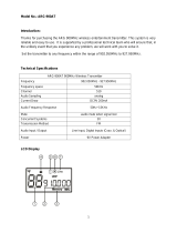
Overview of the displays
After switch-on, the receiver displays the “Bank/Channel” status display.
For further illustrations and examples of the different status displays,
refer to page 38.
Each display provides information on the operating states of the receiver
and those of the received transmitter.
Reception display
쐃 RF level display “RF” for antenna A
쐇 Diversity display (antenna A or antenna B active)
쐋 RF level display “RF” for antenna B
쐏 Audio level display “DEV”
쐄 Display for the squelch threshold
Status display
쐂 Frequency display
쐆 “MHz” – appears when the frequency is displayed
쐊 6-step transmitter battery status display
쐎 Command display (status display for the audio outputs AF and
Command)
(EM 3732-II COM twin receiver only)
쐅 Display for the current frequency bank and channel or the name
Brightness control
The display has an automatic brightness control. The brightness is dimmed
after the last button press. With each new button press, the display lights
up with full brightness.
300
100
30
10
10
50
100
PEAK
µV
RF
% DEV
M
H
z
776.000
01.01
BANK
CH
A B
COM
AF
쐃
쐋 쐏 쐂 쐆 쐊
쐅쐄
쐇
쐎
For additional information, refer to page 10.
For additional information, refer to page 11.
Triggers for dimming after Behavior of the display
No operation 60 s Display is slightly dimmed
Squelch not reached 20 min Display goes off

Product overview
10
Reception display
The reception display is permanently displayed. If you do not press a
button on the receiver, the display will dim after 60 seconds (see page 9).
RF level display “RF” for the antennas
The left bargraph 쐃 shows the strength of the received RF signal for
antenna A; the right bargraph 쐋 shows the strength of the received RF
signal for antenna B.
When the RF signal of the received transmitter is too weak on both
antennas:
•the text “Mute” flashes several times in alternation with the status
display,
• the warning triangle for indicating error states 5 lights up red,
• the receiver is automatically muted to suppress hissing noise.
Display for the squelch threshold
The top edge of the rastered area 쐄 shows the adjusted squelch
threshold. The squelch threshold can be adjusted via the operating menu
(see “Adjusting the squelch threshold” on page 32).
If the squelch threshold is not reached for 20 minutes, the display goes off
(see page 9).
Diversity display
The receivers operate on the true diversity principle (see “Diversity
reception” on page 43). The diversity display 쐇 indicates whether
diversity section A (i.e. antenna A) or diversity section B (i.e. antenna B) is
active. The letter of the active diversity section appears backlit.
Audio level display “DEV”
The audio level display “DEV” 쐏 shows the modulation of the received
transmitter.
When the transmitter’s audio input level is excessively high, the receiver’s
audio level display “DEV” 쐏 shows more than 100 %.
When the transmitter is overmodulated frequently or for an extended
period of time, the text “AF Peak” appears and the warning triangle for
indicating error states 5 lights up red.
300
100
30
10
10
50
100
PEAK
µV
RF
% DEV
A B
쐃
쐋
5
Mute
300
100
30
10
10
50
100
PEAK
µV
RF
% DEV
A B
쐄
300
100
30
10
10
50
100
PEAK
µV
RF
% DEV
A B
쐇
300
100
30
10
10
50
100
PEAK
µV
RF
% DEV
A B
쐏
AF Peak
5

11
Product overview
Status display
The status display shows the receiving frequency, the transmitter battery
status and – depending on the selection made in the “Display” menu –
either the frequency bank and the channel number or the name of the
receiver. With the EM 3732-II COM receiver, the command display can also
be displayed within the status display. The contents of the status display
can be changed in the “Display” menu (see page 38).
When pressing the jog dial 7, the status display is replaced by the
operating menu (see “Working with the operating menu” on page 25).
When in the operating menu, you can return to the status display by
pressing the esc button 6 one or several times.
Frequency display
The frequency display 쐂 shows the current receiving frequency in MHz.
Display for the current frequency bank and channel or the name
The display for the current frequency bank and channel or the name 쐅
shows – depending on the selection made in the “Display” menu – the
following:
•Frequency bank “1...6, U” and channel number “1...60”
•Name
Transmitter battery status display
The 6-step transmitter battery status display 쐊 provides information on
the charge status of the transmitter’s battery/accupack:
When the battery/accupack is almost empty, text “Low Batt” flashes in
alternation with the status display. In addition, the warning triangle for
indicating error states 5 lights up red.
M
H
z
776.000
NAME
M
H
z
776.000
01.01
BANK
CH
Number of segments Charge status
Accupack Battery
approx. 100 % full
approx. 80 % -
approx. 60 % half-full
approx. 40 % -
approx. 20 % -
approx. 0 % almost empty
If no battery/accupack status signal is received, the battery status
display is not shown.
(Low Batt)
Low Batt
5

Product overview
12
Command display (status display of the audio outputs AF and
Command)
The command display is only available with the EM 3732-II COM twin
receiver.
Besides the two audio outputs K and M the EM 3732-II COM twin receiver
also features the two command outputs J and L.
Via the “Command” menu, you can configure the receiver so that – with
the command button of the transmitter pressed – the audio signal is
available at only one of the outputs or at both (see “Configuring the audio
outputs of the EM 3732-II COM” on page 34).
The command display 쐎 shows the audio output at which the
transmitter’s audio signal is available.
When “AF” lights up brightly, the audio signal is available at the audio
output K and/or M.
When “AF” does not appear, the audio signal is not issued on the audio
output K and/or M.
When “COM” lights up brightly, the audio signal is available at the
command output J and/or L.
When “COM” does not appear, the audio signal is not issued on the
command output J and/or L.
LEDs for booster supply of antenna inputs
The LEDs for booster supply of antenna input A N and/or B S light up
when:
• the booster supply voltage is applied to the corresponding antenna
input A O and/or B R.
The LEDs for booster supply of antenna input A N and/or B S go off
when:
• the booster supply voltage for the corresponding antenna input A O
and/or B R is switched off or
• the booster supply voltage is short-circuited or overloaded.
COM
AF
JK
LM
AF
COM
N
OP
Q
R
S

13
Putting the receiver into operation
Putting the receiver into operation
Fitting the device feet
To ensure that the receiver cannot slip on the surface on which it is placed,
four self-adhesive soft rubber feet are supplied.
왘 Ensure that the base of the receiver is clean and free from grease
before fitting the device feet.
왘 Fit the device feet to the four corners of the receiver as shown.
Rack mounting
Do not fit the device feet when rack mounting the receiver.
CAUTION! Risk of staining of furniture surfaces!
Some furniture surfaces have been treated with varnish,
polish or synthetics which might cause stains when they
come into contact with other synthetics. Despite a thorough
testing of the synthetics used by us, we cannot rule out the
possibility of staining.
왘 Do not place the receiver on delicate surfaces.
CAUTION! Risks when rack mounting the receiver!
When installing the receiver in a closed or multi-rack
assembly, please consider that, during operation, the
ambient temperature, the mechanical loading and the
electrical potentials will be different from those of devices
which are not mounted into a rack.
왘 The ambient temperature within the rack must not
exceed the temperature limit specified in the
specifications.
왘 When installing the receiver in a rack, take good care not
to affect the ventilation required for safe operation or
provide additional ventilation.
왘 Make sure the mechanical loading of the rack is even to
avoid a hazardous condition such as a severely
unbalanced rack.
왘 When connecting the receiver to the power supply,
observe the information indicated on the type plate.
Avoid circuit overloading. If necessary, provide
overcurrent protection.
왘 Ensure a reliable mains ground connection of the device
by taking appropriate measures – especially when you
are using an extension cable or a multi-outlet power strip.
왘 When installing the receiver in a closed or multi-rack
assembly, please note that intrinsically harmless leakage
currents of the individual devices may accumulate,
thereby exceeding the allowable limit value. As a remedy,
ground the rack via an additional ground connection.

Putting the receiver into operation
14
The rack mount “ears” are already fitted to the receiver on delivery. To
mount the receiver into a 19" rack:
왘 Slide the receiver into the 19" rack.
왘 Secure the rack mount “ears” 1 to the rack using four screws (not
included in the delivery).
Connecting the antennas
The two antenna inputs O and R allow you to connect either:
• the two supplied antennas to the rear of the receiver (see next section)
or
• the two supplied antennas to the front of the receiver (see “Mounting
the antennas to the front of the rack” on page 15) or
• two remote antennas to the rear of the receiver (see “Connecting and
positioning remote antennas” on page 16).
In addition, the receiver has two daisy chain outputs P and Q for
supplying the antenna signals to further receivers (see “Daisy chaining
receivers” on page 16).
Connecting the antennas to the rear of the receiver
The supplied antennas can be mounted quickly and easily and are suitable
for all applications where – good reception conditions provided – a
wireless transmission system is to be used without a large amount of
installation work.
왘 Connect the antennas to the BNC sockets O and R at the rear of the
receiver.
왘 Align the antennas upwards in a V-shape.
CAUTION! Danger of short-circuit due to uninsulated antennas!
If you switch the booster supply voltage on, a 12 V DC voltage
is applied to the antennas – even when you switch the
receiver off! If uninsulated antennas come into contact with
objects which conduct electricity, this voltage can produce
sparking and audio interference.
왘 Use insulated antennas.
OR
왘 Always mount uninsulated antennas so that they cannot
come into contact with objects which conduct electricity.
N
OP
Q
R
S

15
Putting the receiver into operation
Mounting the antennas to the front of the rack
To mount the antenna connections to the front of the rack when rack
mounting the receiver, you require the GA 3030 AM antenna front mount
kit (optional accessory). The GA 3030 AM consists of:
• 2 BNC extension cables (screw-in BNC socket W to BNC connector [),
•2 antenna holdersZ,
• 4 screws,
•2 washersY,
•2 nutsX.
왘 Unsecure the rack mount “ears” 1 from the rack.
왘 Guide the BNC cables through the holes in the rack mount “ears” as
shown in the diagram on the left.
왘 Screw the antenna holders Z to the BNC sockets W using the supplied
washers Y and nuts X.
왘 Secure the antenna holders Z to the handles of the receiver using two
of the supplied screws respectively.
왘 Connect the two BNC connectors [ to the BNC sockets O and R at the
rear of the receiver.
왘 Slide the receiver into the 19" rack.
왘 Resecure the rack mount “ears” 1 to the rack.
왘 Connect the antennas \ to the BNC sockets W.
왘 Align the antennas upwards in a V-shape.
Y
W
X
-II
W
1
Z
W
X
Y
-II
Z
-II
[
\

Putting the receiver into operation
16
Connecting and positioning remote antennas
Use remote antennas when the position of the double receiver is not the
best antenna position for optimum reception. Remote antennas are
available as accessories.
왘 Connect the remote antennas to the BNC sockets O and R using a low-
attenuation 50-Ω coaxial cable.
왘 If you connect active antennas (e.g. A 3700, AD 3700) or antenna
boosters (e.g. AB 3700), switch on the DC supply voltage for external
active antennas and antenna boosters (see page 32) so that the
LEDs N and/or S light up;
if you do not connect active antennas or antenna boosters, switch off
the booster supply voltage so that the LEDs N and/or S do not light
up.
왘 Position antennas in the same room in which the transmission takes
place! Maintain a minimum distance of 1 m between antennas and a
minimum distance of 50 cm between antennas and metal objects
(including reinforced concrete walls).
Daisy chaining receivers
The receivers feature an integrated antenna splitter so that up to eight
receivers can be daisy chained using the supplied short antenna daisy
chain cables. The type plate U indicates the daisy chained frequency
range.
왘 Connect the two supplied antennas or two remote antennas (available
as accessories) to the BNC sockets O and R at the rear of the first
receiver.
왘 Use the supplied 50-Ω antenna daisy chain cables to daisy chain the
receivers as shown in the diagram on the left.
N
OP
Q
R
S
Ready-made coaxial antenna cables from Sennheiser are available
as accessories with length of 1m, 5m and 10m (see “Accessories”
on page 45).
If the booster supply voltage is switched on (see page 32), it
remains switched on even when the receiver is switched off.
ANT A ANT B
V
The antenna signals are also daisy chained when a receiver is
switched off. If the booster supply voltage is switched on (see
page 32), it remains switched on even when the receiver is
switched off.

17
Putting the receiver into operation
Connecting the receiver to the mains/
disconnecting the receiver from the mains
The receiver has no mains switch. To connect the receiver to the mains:
왘 Connect the supplied mains cable to the 3-pin mains socket D.
왘 Plug the mains connector into the wall socket.
To disconnect the receiver from the mains:
왘 Pull out the mains connector from the wall socket.
All daisy chained signals are interrupted, i.e.:
– the antenna signals at the daisy chain outputs Q and P,
– the booster supply voltage,
– the signal of the external word clock generator.
Connecting the amplifier/mixing console
The receiver has transformer balanced audio outputs.
왘 Connect the amplifier/mixing console to the XLR-3 socket
AF Out 1 M (left receiver) or to the XLR-3 socket AF Out 2 K (right
receiver).
왘 Via the operating menu of the corresponding receiver, adjust the level
of the audio output to the input of the amplifier or mixing console (see
“Adjusting the audio output level” on page 33).
CAUTION! Damage to the device due to electric current!
If you connect the receiver to an unsuitable power supply,
this can cause damage to the device.
왘 Use the supplied mains cable to connect the receiver to
the mains (100 to 240 V AC, 50 or 60 Hz).
왘 Ensure a reliable mains ground connection of the receiver
– especially when you are using multi-outlet power strips
or extension cables.
D
K
M

Putting the receiver into operation
18
Connecting devices with AES3 digital input
The digital balanced XLR-3M audio output G outputs the signals of both
receivers in AES3 format.
왘 Use a special double-shielded 110 Ω AES3 cable to connect the device
with AES3 digital input to the digital balanced XLR-3M audio output G.
This prevents that the digital data transmission interferes with RF
reception.
왘 Via the “Clock” menu, select the desired sampling rate (see “Selecting
the sampling rate for digitalization” on page 34).
Connecting an external word clock generator
The receiver can digitalize the audio signal and output it via the digital
balanced XLR-3M audio output G. The built-in A/D converter supports
sampling rates of 44.1 kHz, 48 kHz, 88.2 kHz and 96 kHz.
If you want to connect an external word clock generator instead, proceed
as follows:
왘 Use a shielded 75 Ω coaxial BNC cable to connect the external word
clock generator to the BNC socket H.
왘 From the “Clock” menu, select “Ext.” (see “Selecting the sampling rate
for digitalization” on page 34).
The display for external word clock synchronization B:
– lights up permanently when the digital audio output of the receiver
is synchronized with the external word clock generator,
– flashes when “Ext.” is selected in the “Clock” menu but no external
word clock generator is connected,
– flashes when the signal of the external word clock generator is
available but has not synchronized the digital audio output of the
receiver,
– is off when the receiver’s internal word clock generator is used.
G
A ready-made AES3 cable from Sennheiser is available as an
accessory with a length of 10 m (see “Accessories” on page 45).
H
I
• Both receivers of a twin receiver use the same word clock signal.
• The receiver has a BNC socket for word clock daisy chain
output I for supplying the word clock signal to further daisy
chained receivers using the supplied BNC word clock daisy chain
cable. The word clock signal is also daisy chained when a
receiver is switched off.

19
Putting the receiver into operation
Connecting the receivers to a PC via Ethernet
The receivers can be centrally configured and monitored via a PC and the
supplied “Wireless Systems Manager” software. Additionally, you can
update the firmware in the receivers.
왘 Connect the supplied RJ 45 Ethernet cable to the RJ 45 socket for LAN
connection F and to your switch or network.
왘 Install the “Wireless Systems Manager” software on your PC.
왘 Continue as described in the instruction manual of the “Wireless
Systems Manager” software.
The LED for LAN data transmission E lights up when data is
transmitted.
When you are working with the “Wireless Systems Manager” software,
you can use the “Spectrum Analyzer” tool to perform a continuous
frequency scan. The “Spectrum Analyzer“ tool uses the receiver that you
select to check the relevant frequency range for signals and records the
corresponding measured values. For detailed information, please refer to
the chapter “The ’RF Spectrum Analyzer’ tool” of the “Wireless Systems
Manager” manual.
When selecting this receiver in the “Spectrum Analyzer”, please note that
during the frequency scan:
•you cannot use the selected receiver for its normal purpose,
•the text “Scanning” is displayed and
• the receiver is automatically muted.
If you want to connect several receivers to the same Ethernet
socket of your network, you require a standard 100Base-T Ethernet
switch.
Scanning
/