Page is loading ...

DPoE™ Power Patch Panel
User’s Guide
Part Numbers: DPOE24U1X, DPOE24U1XY,
DPOE12U1X, DPOE12U1XY, DPOE24S1X,
DPOE24S1XY
Issue 2.2
Part Number: PN378A
August 2006
© 2006 PANDUIT Corp.
All Rights reserved
www.panduit.com

PANDUIT® DPoE™ Power Patch Panel User’s Guide Issue 2.2
Part Number: PN378A
i
Safety Warning
Always observe standard safety precautions during installation, operation and maintenance of this
product. Read the installation instructions before you connect the unit to its power source. This unit must
be connected to earth ground, do not bypass the grounding system. To avoid the possibility of electric
shock, disconnect the power cord from the power source before removing the cover or performing any
repairs. Only a competent technician who is aware of the hazards involved should carry out adjustment
maintenance or repairs. The operator or user should perform no adjustment, maintenance or repairs to
the opened instrument. There are no user serviceable parts inside the unit. Do not work on the system or
connect or disconnect cables during periods of lightning activity. Ultimate disposal of this product should
be handled according to all national laws and regulations.
WARRANTY
Unless otherwise specified, all products presented in this user's guide are warranted against
defects in material and workmanship for a period of one year from the date of sale to the initial
purchaser. PANDUIT Corp. warrants that its firmware designed by PANDUIT Corp. for use with
the product will execute its functions when properly installed in the product for one year from the
date of sale to the initial purchaser. PANDUIT Corp. does not warrant that the operation of the
product or the firmware will be uninterrupted or error-free. During the warranty period PANDUIT
Corp. will, at its discretion, either repair or replace products that prove to be defective. For
warranty service or repair, the product claimed to be defective must be returned to a service
facility designated by PANDUIT Corp. Buyer shall prepay all the shipping charges to PANDUIT
Corp. and if, in the opinion of PANDUIT Corp., the product is defective, PANDUIT Corp. shall
pay shipping charges to return the product to Buyer. However, Buyer shall pay all shipping
charges, duties and taxes for products returned to PANDUIT Corp. from another country.
The foregoing warranty shall not apply to defects resulting from, buyer-supplied firmware or
unauthorized interfacing, modification or misuse of the product, operation outside of the
environmental specifications for the product, or improper or inadequate site preparation or
maintenance by Buyer.
NO OTHER WARRANTY IS EXPRESSED OR IMPLIED. PANDUIT CORP. SPECIFICALLY
DISCLAIMS THE IMPLIED WARRANTIES OF MERCHANTABILITY AND FITNESS FOR A
PARTICULAR PURPOSE.
THE REMEDIES PROVIDED HEREIN ARE BUYER'S SOLE AND EXCLUSIVE REMEDIES.
PANDUIT CORP. SHALL NOT BE LIABLE FOR ANY DIRECT, INDIRECT, SPECIAL,
INCIDENTAL OR CONSEQUENTIAL DAMAGES, WHETHER BASED ON CONTRACT, TORT
OR OTHER LEGAL THEORY.
Unless otherwise specified by PANDUIT Corp., opening of this product by unauthorized
personnel will void this warranty.
TRADEMARKS
DPoE
™
is a trademark of PANDUIT
®
Corp. All other trademarks are the property of their
respective owners.

PANDUIT® DPoE™ Power Patch Panel User’s Guide Issue 2.2
Part Number: PN378A
ii
TABLE OF CONTENTS
Safety Warning................................................................................................................. i
WARRANTY..................................................................................................................... i
TRADEMARKS ................................................................................................................ i
OVERVIEW..................................................................................................................... 5
Features and Benefits.................................................................................................. 6
INSTALLATION For DPOE24U1X, DPOE24U1XY, DPOE12U1X and DPOE12U1XY
(For DPOE24S1X and DPOE24S1XY see Appendix 1).................................................. 8
Package Contents ....................................................................................................... 8
Panel Mounting Procedure ........................................................................................ 10
Rack Mounting Instructions ................................................................................ 10
Grounding Requirements ................................................................................... 11
Network Connection ........................................................................................... 11
Connecting the Powered Devices.............................................................................. 11
Power Requirements ................................................................................................. 13
Powering Up the DPoE™ Power Patch Panel........................................................... 14
Basic Troubleshooting ............................................................................................... 15
OPERATION ................................................................................................................. 17
LED Indicators ........................................................................................................... 17
ELEMENT MANAGER SOFTWARE............................................................................. 19
Hardware and Software Requirements...................................................................... 19
Installing the Element Manager Software .................................................................. 20
Connecting the EM Host Computer to the DPoE™ Power Patch Panel .................... 21
Element Manager Operation...................................................................................... 22
Graphical User Interface..................................................................................... 23
Additions or Changes to UserName/Password................................................... 24
Panel Discovery.................................................................................................. 26
Subnetwork Search................................................................................... 27
IP Range Search....................................................................................... 28
Provisioning the Panel........................................................................................ 29
Administering Port and Panel-level Information.................................................. 33
Edit Panel Information............................................................................... 33
− Panel IP Address......................................................................... 34
− Panel Attributes ........................................................................... 34
− SNMP Settings ............................................................................ 35
− Trap Settings ............................................................................... 35
Copy/Paste/Delete Panel Information ....................................................... 36
Export Panel Information........................................................................... 36
View Port Information................................................................................ 37
− Edit Port Information.................................................................... 38
Export Log................................................................................................. 40
View Entire Log ......................................................................................... 41
− Filter Log Messages .................................................................... 42
− Export Log ................................................................................... 42
− Clear Log ..................................................................................... 43

PANDUIT® DPoE™ Power Patch Panel User’s Guide Issue 2.2
Part Number: PN378A
iii
Refresh the Network........................................................................................... 43
Administering E-mail Settings............................................................................. 43
Search for Specific Panel(s) or Port(s) ............................................................... 45
EM Log Messages.............................................................................................. 47
Miscellaneous Settings....................................................................................... 48
DPoE™ Power Patch Panel Firmware Update................................................... 49
Detailed Description of the Firmware Update ..................................................... 50
Exiting the PANDUIT
®
Element Manager............................................................ 52
APPENDIX 1 – DPOE24S1X AND DPOE24S1XY INSTALLATION ............................. 53
Package Contents ..................................................................................................... 53
Panel Mounting Procedure ........................................................................................ 55
Rack Mounting Instructions ................................................................................ 55
Networking The Panels (Optional)...................................................................... 58
Power Requirements ................................................................................................. 59
Powering Up the DPoE™ Power Patch Panel........................................................... 61
TECHNICAL SPECIFICATIONS ................................................................................... 62
GLOSSARY .................................................................................................................. 63
Figures
Figure 1: DPoE™ Power Patch Panel (Front View) ........................................................ 5
Figure 2: DPoE™ Power Patch Panel (Rear View)......................................................... 6
Figure 3: System-Level Opening Screen....................................................................... 23
Figure 4: View Panel Screen......................................................................................... 33
Figure 5: Edit Panel Screen .......................................................................................... 34
Figure 6: View All Ports Screen..................................................................................... 38
Figure 7: View Individual Port Screen ........................................................................... 39
Figure 8: View Message Log Screen............................................................................. 41
List of Tables
Table 1: Power Supplies Available from PANDUIT Corp. ............................................... 8
Table 2: Package Contents ............................................................................................. 8
Table 3: PANDUIT Corporation Contact Information....................................................... 9
Table 4: Color-Coded Wire Positions for 802.3af-2003 Compliant Devices .................. 12
Table 5: Color-Coded Wire Positions for Alternate PoE Devices .................................. 12
Table 6: DPoE™ Power Patch Panel Power Up Sequence .......................................... 15
Table 7: Basic Troubleshooting Guide .......................................................................... 16
Table 8: Panel Status LED Indications .......................................................................... 17
Table 9: Port Status LED Indications............................................................................. 17
Table 10: Network Status LED Indications .................................................................... 18
Table 11: PC Minimum Requirements for EM ............................................................... 19
Table 12: EM Log Messages......................................................................................... 47
Table 12A: DPoE™ Power Patch Panel Firmware Update LED Status ........................ 51
Table 13: Power Supplies Available from PANDUIT Corp. ........................................... 53

PANDUIT® DPoE™ Power Patch Panel User’s Guide Issue 2.2
Part Number: PN378A
iv
Table 14: Package Contents ......................................................................................... 53
Table 15: PANDUIT Corp Contact Information.............................................................. 54
Table 16: Color-Coded Wire Positions for 802.3af-2003 Compliant Devices ................ 57
Table 17: Color-Coded Wire Positions for Alternate PoE Devices ................................ 57
Table 18: DPoE™ Power Patch Panel Power Up Sequence ........................................ 61

PANDUIT® DPoE™ Power Patch Panel User’s Guide Issue 2.2
Part Number: PN378A
5
OVERVIEW
The DPoE™ Power Patch Panel provides a reliable and cost-effective solution for Power over Ethernet
(PoE) applications, complaint with the IEEE 802.3af-2003 specifications. Each DPoE™ Power Patch
Panel allows centralized powering of up to 24 devices, such as Internet Protocol-based (IP) telephones,
Network Security Cameras, or Wireless Devices, over the same cabling used to provide the Ethernet
connectivity. By eliminating separate power connections to each of the devices, the DPoE™ Power Patch
Panel provides a more cost-effective solution, particularly in cases where the devices are numerous or
local powering is impractical.
The DPoE™ Power Patch Panel can be used in place of current patch panels to inject PoE power into an
existing infrastructure without the need for separate non-powered patch panels (i.e., hub architectures),
which decrease reliability while increasing cost and wiring complexity.
While the DPoE™ Power Patch Panel may be used as a standalone device, it can be configured and
monitored from a centralized PANDUIT
®
Element Manager (EM). This management system allows
network operators to remotely perform routine maintenance and monitoring of any DPoE™ Power Patch
Panels in their network. The EM allows operators to graphically view and monitor power panel status,
fault conditions and per-port power consumption. In addition, the EM allows the operator to designate
power priority to individual ports within each DPoE™ Power Panel. A higher-level Network Management
System (NMS) might then use this pre-configured information to guarantee mission-critical devices
remain operational in the event of low-power conditions.
RJ-45 connector
(one per port)
Port Status LED
(one per port)
Panel Status
LED
23 24
Port number
Figure 1: DPoE™ Power Patch Panel (Front View)

PANDUIT® DPoE™ Power Patch Panel User’s Guide Issue 2.2
Part Number: PN378A
6
A
- and B-feed
(optional) Power
Connections
Punchdown
connections
OUT management
port and OUT
Network Status LED
IN management port
and IN Network Status
LED
Figure 2: DPoE™ Power Patch Panel (Rear View)
Features and Benefits
The following table highlights some of the capabilities of the DPoE™ Power Patch Panel along with the
tangible benefit to the network operator.
DPoE™ Power Patch Panel Feature Benefit
Powers up to 24 devices from a
centralized location
By using PoE, a network operator can more
cost-effectively power Ethernet devices up to
100 m (328 ft.) from the PANDUIT® DPoE™
Power Patch Panel. Powering from a
centralized location eliminates the need to
power each device separately, eliminates the
need for separate Uninterruptible Power
Supply (UPS) for critical devices, and allows
centralized power management by the
network operator.
Combining PoE Power with patch panel
functionality
Other vendors use a separate “Power Hub”
architecture, which doesn’t replace the need
for additional non-powered patch panels.
PANDUIT® DPoE™ Power Patch Panel
combines these two functions into a 1 RU-
high package. This reduces needed rack
space by at least 50% while providing easier
installation without the need for patch cords
between the Power Hub and a non-powered
patch panel.

PANDUIT® DPoE™ Power Patch Panel User’s Guide Issue 2.2
Part Number: PN378A
7
DPoE™ Power Patch Panel Feature Benefit
IEEE 802.3af-2003 Compliant Many currently available in-line PoE
powering options are not standards-based,
thus requiring coordination between each
device’s power needs and the technical
capabilities of the in-line powering unit.
Any port on the PANDUIT® DPoE™ Power
Patch Panel can support the 802.3af-2003
standard or the legacy Cisco powering
scheme.
Full power to all ports With all ports on the panel capable of
delivering full PoE power, there’s no need to
load balance across panels, design special
wiring schemes or leave ports unused in the
panel.
Increased System Reliability The PANDUIT® DPoE™ Power Patch Panel
does not use an internal fan. Fans reduce
the system reliability. In addition, the
eliminated need for separate “midspan”
patch panels increases the network
availability.
Simultaneous support for the Cisco
powering scheme along with the 802.3af-
2003 standard
By supporting both methods on each port,
the DPoE™ Power Patch Panel provides
ultimate flexibility without the need for
separate panels for each powering scheme
and without the need to install separate
power modules. In addition, devices that
don’t require PoE powering may also be
mixed in the same panel.
Power Prioritization In the event of low-power conditions, a NMS,
working in conjunction with the DPoE™
Power Patch Panels, can use the pre-
established port priorities to ensure mission-
critical ports on the network of panels
continue to receive PoE power as long as
possible.
Easier Local Management Multi-colored LEDs on the DPoE™ Power
Patch Panel allow technicians to instantly
know the status of each port. Additional
LEDs reflect management and panel status.
Identification labels on the front and rear of
the system allow the technician to note the
panel number, the port number and wiring
scheme information for both the Ethernet
and PoE sides of the panel.
Easier Remote Management The optional EM allows network operators to
easily view and manage a network of
DPoE™ Power Patch Panels using industry-
standard Simplified Network Management
Protocol (SNMP).

PANDUIT® DPoE™ Power Patch Panel User’s Guide Issue 2.2
Part Number: PN378A
8
DPoE™ Power Patch Panel Feature Benefit
Easier Installation By eliminating the need for separate
midspan patch panels and the associated
need for patch cord, in a network-ready 1RU
high package, The DPoE™ Power Patch
Panel is fast and easy to install.
INSTALLATION For DPOE24U1X, DPOE24U1XY, DPOE12U1X
and DPOE12U1XY (For DPOE24S1X and DPOE24S1XY see
Appendix 1)
The PANDUIT® DPoE™ Power Patch Panel requires a direct connection to a nominal 48VDC supply.
An individual power supply may be purchased separately from PANDUIT Corp or other vendors.
Installation instructions for the individual power supply are included with that product. PANDUIT Corp
provides multiple individual power supply options as listed below.
Table 1: Power Supplies Available from PANDUIT Corp.
PANDUIT Part Number Description
DPOEPWRB120 120 watt power brick - 48 volt output
DPOEPWRCU
Unmanaged power chassis - supports 3
rectifiers and optional Network Interface Card
(NIC)
DPOEPWRR500
500 watt rectifier for use in the DPOEPWRCU
chassis
DPOEPWRR1250
1250 watt rectifier for use in the DPOEPWRCU
chassis
CORD-A Power cord for Australia
CORD-E Power cord for Europe
CORD-S Power cord for USA
CORD-U Power cord for the U.K.
Package Contents
Each PANDUIT® DPoE™ Power Patch Panel is shipped in a box, which includes the following:
Table 2: Package Contents
Item Quantity Notes
DPoE™ Power Patch Panel 1 DPOE24U1X, DPOE24U1XY,
DPOE12U1X or DPOE12U1XY
Wiring Template Label 1 For use on the rear panel of the
DPoE™ Power Patch Panel –
Supports either EIA/TIA 568A or
568B wire positions.

PANDUIT® DPoE™ Power Patch Panel User’s Guide Issue 2.2
Part Number: PN378A
9
Item Quantity Notes
Quick Installation Instructions 1 PANDUIT Part Number PN370
DPOE™ Installation Worksheet 1 PANDUIT Part Number PN377
Metric and English screws 12 Installation requires six screws.
One bag of six metric screws
(M6x1.0x16) and one bag of six
English screws (12-24x1/2”) are
included.
8 inch grounding strap 1
DPoE™ Power Patch Panel Support Tools CD-
ROM containing:
- PANDUIT
®
Element Manager (EM)
software.
- DPoE™ Power Patch Panel Users Guide
(this document)
- Release Notes
- Application Notes
- Installation Guides
1
Power connector housing with wire leads 1 This wiring harness is used to
connect the DPoE™ Power Patch
Panel to the 48VDC power
supply. Not used if the panel is
powered by the PANDUIT Power
Brick (PANDUIT Part Number
DPOEPWRB120 or
DPOEPWRB120Y.)
10 Foot Power Harness 1 Used to connect the –48V A-feed
to a power supply.
Butt splices 2 Two butt splices may be used to
extend the 10 Foot Power
Harness. (Do not exceed a total
length of 35 feet).
Verify the above contents arrived in good condition. If not, contact PANDUIT Technical Support.
Table 3: PANDUIT Corporation Contact Information
PANDUIT Technical Support Fax: 1-708-444-6993
E-mail: [email protected]
For Installation Instructions in Local Languages
and Technical Support
www.panduit.com/resources/install_maintain.asp
Worldwide Subsidiaries and Sales Offices www.panduit.com
Latest Software Updates www.panduit.com/managednetworksolutions

PANDUIT® DPoE™ Power Patch Panel User’s Guide Issue 2.2
Part Number: PN378A
10
IMPORTANT:
The DPOE™ Installation Worksheet should be used to record pertinent
information when installing DPoE™ Power Patch Panel(s), particularly if the EM is
monitoring the network. (See page 29, Provisioning the Panel, for more
information on how this information will be entered in the EM.) The installer
should complete this worksheet.
Panel Mounting Procedure
WARNING:
Only trained and qualified service personnel should install or service
DPoE™ Power Patch Panels
WARNING:
Before installing or servicing DPoE™ Power Patch Panels or
communication wiring, be aware of the hazards with the associated
electrical circuitry.
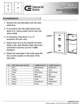
Rack Mounting Instructions
1. Record the MAC address, printed on a
sticker on the back of the unit, by
writing it in the space provided on the
included Installation Worksheet
(PANDUIT part number PN377).
2. Slip the Wiring Template Label over
the rows of connectors on the back of
the DPoE™ Power Patch Panel,
making sure the proper wiring code is
facing out and that the writing is not
upside down. One side of the label indicates EIA/TIA 568A wiring, while the other side is EIA/TIA
568B wiring.
3. Using a screw from the US standard thread screw set denoted by “01881-38 REV 2,” attach the
green and yellow striped grounding strap to the panel via the unthreaded hole nearest the
power connector. Next, install the panel onto a grounded rack using the appropriate screw set
provided to ensure proper grounding between the panel and the rack. Finally, attach the loose
end of the grounding strap to the rack within the same position as the panel.
PANDUIT Structured Ground Kits for Data Center Rack Grounding can be used to properly ground
PANDUIT® NetRack Rack Systems and racks from most other manufacturers.
4. Using four of the enclosed metric or English screws, as appropriate, install the DPoE™ Power
Panel into the 19” rack at the planned rack position.
WARNING:
The supplied screws are part of a grounding system to ensure that the
DPoE™ Power Patch Panel is properly grounded to the rack.
USE ONLY THE SUPPLIED SCREWS TO ATTACH THE PANEL TO
THE RACK.
Record the rack space position on the Installation Worksheet.

PANDUIT® DPoE™ Power Patch Panel User’s Guide Issue 2.2
Part Number: PN378A
11
From
Network
Grounding Requirements
Network Connection
5. If the Element Manager is not being used to
remotely manage the network of DPoE™
Power Patch Panels, skip to Connecting the
Powered Devices below. Otherwise, using a
standard patch cord (for example, PANDUIT
part number UTPCH3 or UTPSP3), connect
the IN management port on the back of the
panel to an Ethernet switch. A DHCP Server
must be on this network (unless the DPoE™
Power Patch Panel has been configured for
Static IP operation). The panel may also be
directly connect to a PC with the PANDUIT
Element Manager installed, but this PC must
be setup as a DHCP Server.”
6. If multiple panels are being used in the network,
the OUT management port from one panel may
be connected to the IN management port on the
next panel in a daisy chain fashion, as shown.
Once all of the connections are made, the EM
or another Network Manager will be able to
communicate with all the panels over this daisy
chain of connections. (See page 29,
Provisioning the Panel, for more information.)
Connecting the Powered Devices
7. Remove 1 inch (25.4 mm) of cable jacket being careful not to damage the conductors.

PANDUIT® DPoE™ Power Patch Panel User’s Guide Issue 2.2
Part Number: PN378A
12
8. Fan out all four twisted pairs in the specified wiring
sequence (see color-coded wiring positions in Table 4:
Color-Coded Wire Positions for 802.3af-2003
Compliant Devices and Table 5: Color-Coded Wire
Positions for Alternate PoE Devices below). The
colors are also displayed on the Wiring Template
Label, already installed on the back of the DPoE™
Power Patch Panel.
The DPoE™ Power Patch panel supports standard IEEE 802.3af-2003 devices as well as
alternate PoE devices consistent with the Cisco legacy devices.
Table 4: Color-Coded Wire Positions for 802.3af-2003 Compliant Devices
Pin
Outs EIA/TIA 568A
Pin
Outs EIA/TIA 568B
5 WHITE/BLUE 5 WHITE/BLUE
4 BLUE 4 BLUE
1 WHITE/GREEN 1 WHITE/ORANGE
2 GREEN 2 ORANGE
3 WHITE/ORANGE 3 WHITE/GREEN
6 ORANGE 6 GREEN
7 WHITE/BROWN 7 WHITE/BROWN
8 BROWN 8 BROWN
Table 5: Color-Coded Wire Positions for Alternate PoE Devices
Pin
Outs EIA/TIA 568A
Pin
Outs EIA/TIA 568B
5 WHITE/BROWN 5 WHITE/BROWN
4 BROWN 4 BROWN
1 WHITE/GREEN 1 WHITE/ORANGE
2 GREEN 2 ORANGE
3 WHITE/ORANGE 3 WHITE/GREEN
6 ORANGE 6 GREEN
7 WHITE/BLUE 7 WHITE/BLUE
8 BLUE 8 BLUE
NOTE:
The DPoE™ Power Patch Panel can terminate most 22-24 AWG solid or stranded
IWC wire with a .050” (1.27mm) max o.d. either PVC or Plenum rated.

PANDUIT® DPoE™ Power Patch Panel User’s Guide Issue 2.2
Part Number: PN378A
13
9. Lay conductors into the punchdown slots for the
specified port using the correct wiring sequence. Cable
jacket removal should be minimized to the extent
possible. Conductor untwist should be within ½” (12.7
mm) of termination.
WARNING:
NEVER TOUCH UNINSULATED COMMUNICATIONS WIRING OR
TERMINALS UNLESS THE COMMUNICATION LINE HAS BEEN
DISCONNECTED AT THE NETWORK INTERFACE.
NOTE:
Never install wiring in a slot previously used for a larger gauge wire.
10. Using the punchdown tool (PANDUIT part number PDT110), punch down the connector into the
punchdown slots on the back of the DPoE™ Power
Patch Panel.
Power Requirements
11. If the panel is being powered by a PANDUIT® DPoE™ Power Brick (See page 8, Table 1: Power
Supplies Available from PANDUIT Corp for a list of available powering options), skip to Powering
Up the DPoE™ Power Patch Panel Section below, since the brick is equipped with a matched
keyed power connector that will fit the power connector on the back of the panel.
12. If the PANDUIT® DPoE™ Power Chassis or a direct 48VDC source is powering the panel, cut
the 10-foot power harness to length then strip the ends of the leads to 5/16” (7.9 mm). Connect
the stripped ends of the power harness into the PANDUIT® DPoE™ Power Chassis. If the power
harness is not long enough or the 48VDC source requires a specific connector, strip the ends of
the wire to the same strip length, being careful not to damage the conductors.
13. Using the two butt splices provided with the panel, and paying attention to the polarity of the
supply voltage, crimp the power harness wires to the supply wires. A crimping tool, such as the
PANDUIT part number CT-100, may be used. The provided butt splices (PANDUIT part number
BSV14X) support 14-16 AWG solid or stranded wire.

PANDUIT® DPoE™ Power Patch Panel User’s Guide Issue 2.2
Part Number: PN378A
14
WARNING:
The power supply connections are polarized.
The DPoE™ Power Panel will not function if power is wired improperly.
For Maximum power the overall length of the wire between the power
supply and the DPoE™ Power Panel must not exceed 35 feet.
NOTE:
The included power harness has two wires for the A-feed power only (pins
1 & 2). The DPoE™ Power Patch Panel supports an optional redundant
B-feed power option, but the terminals and wire leads are not attached to
the power harness.
Contact PANDUIT Technical Support for more information about
connecting the redundant B-Feed Power.
14. Lightly tug on the butt spliced connections to verify that the butt splices are secure.
Powering Up the DPoE™ Power Patch Panel
15. Plug the connector into the back of the DPoE™ Patch
Panel.
16. Once power is applied to the unit, the DPoE™ Power Patch
Panel will go through its power up sequence. The following
table describes the behavior of the unit as viewed from the
front and the back.

PANDUIT® DPoE™ Power Patch Panel User’s Guide Issue 2.2
Part Number: PN378A
15
Table 6: DPoE™ Power Patch Panel Power Up Sequence
Behavior as viewed from the back of the unit Behavior as viewed from the front of the unit
Both network status LEDs will light amber for two
seconds
The panel status Light-Emitting Diode (LED) will
light red for about 10 seconds. After that, a LED
test sequence of the port status LEDs will take
place, lighting each port status LED amber. It will
appear as if the port status LED is “walking” from
port 1 through port 24.
If there is no cable connected to the IN
management port (Step 5 above), both network
status LEDs will turn off.
If the Patch Panel is configured for Dynamic Host
Control Protocol (DHCP) address assignment
(default configuration) and a cable is NOT
connected to the IN management port on the rear
of the panel, the panel status LED will turn green.
If the DPoE™ Power Patch Panel is configured
for DHCP address assignment (default factory
setting), the network status LED above the IN
management port will stay amber and the
network status LED above the OUT management
port will turn off. This indicates that the panel is
actively requesting address information from the
network. Once this information is received (this
could take up to a minute), the network status
LED above the IN management port will turn on
or start flashing green as data is transmitted and
received.
If the DPoE™ Power Patch Panel is configured for
DHCP address assignment (default factory setting),
the panel status LED will flash amber. This
indicates that the panel is actively requesting
address information from the network. Once this
information is received (this could take up to a
minute), the panel status LED will flash green. (See
page 5, Figure 1: DPoE™ Power Patch Panel
(Front View) and page 6, Figure 2: DPoE™ Power
Patch Panel (Rear View) for a graphical view of the
LEDs on the DPoE™ Power Patch Panel.)
If the panel were set to static IP addressing rather
than DHCP, the network status LED above the IN
management port will immediately turn green.
If the panel were set to static IP addressing rather
than DHCP, the panel status LED will flash green
and continue flashing as long as power is applied
to the unit.
Basic Troubleshooting
Use the following guide to help resolve problems installing the DPoE™ Power Patch Panel. If the problem
persists, contact PANDUIT Corp Technical Support or a local sales representative. (See page 9, Table 3:
PANDUIT Corporation Contact Information, for contact information.)

PANDUIT® DPoE™ Power Patch Panel User’s Guide Issue 2.2
Part Number: PN378A
16
Table 7: Basic Troubleshooting Guide
Problem Possible Causes and Solutions
The panel status LED does not light when power
is applied to the unit.
1. The power supply fuse may be blown. Check
the fuse on the DPoE™ Power Patch Panel
power supply.
2. The power connection may be bad. Check the
physical connection and make sure the voltage
polarity is proper.
3. No power is available at the panel. Make sure
the power supply is plugged in and operational.
4. The keyed power connector is not seated
properly. Reseat the power connector.
The patch panel status LED is flashing green but
no power is being applied to the connected
powered device(s). The port status LED over the
port(s) where power should be provided is off.
1. The device is not connected properly to the
DPoE™ Power Patch Panel. Make sure that
the cable to the connected devices is properly
terminated on the panel for the type of power
needed (IEEE 802.3af-2003 or Alternate PoE)
1
.
2. The cable is not punched down securely. Re-
punch the 110 connections.
3. The attached power device is not 802.3af-2003
compliant or legacy Cisco compliant. Make
sure that the attached device meets either of
these standards. Also try to connect the device
to another port to see if it powers on.
4. The port Administration Control setting is set to
OFF in the EM. The Element Manager must be
used to set the port Administration Control to
ON. (See page 38, Edit Port Information, for
more information.)
The panel status LED stays solid red after power
is connected and over 20 seconds has elapsed.
1. The power supply voltage is either less than 46
volts or greater than 57 volts. The panel should
be immediately disconnected from power and
the input power should be corrected.
The DPoE™ Power Patch Panel is providing
power to the end device, but there is no data
connection (i.e., the Ethernet connection is not
working).
1. The switch is not properly connected to the RJ-
45 jacks on the front of the panel or the switch.
Check for proper connections and establish the
connections or reseat these if required.
2. The switch port may not be active. Check with
the local IT person to see if this is the case and
correct it.
3. The data pairs (1,2 and 3,6) are not properly
terminated on the rear of the DPoE™ Power
Patch Panel. Re-punch the port(s) and test the
connection again.
1
If a port is wired as Alternate POE, both IEEE 802.3af-2003 Powered Devices as well as legacy Cisco
Powered Devices will be detected and get powered up. If a port is wired as POE, only the IEEE 802.3af-
2003 Powered Devices will be detected and get powered up.

PANDUIT® DPoE™ Power Patch Panel User’s Guide Issue 2.2
Part Number: PN378A
17
OPERATION
LED Indicators
The DPoE™ Power Patch Panel displays system and port status through the use of LEDs on the front
and rear of each panel. There is one panel status LED on the front left of the panel, 24 individual port
status LEDs above each port, and twonetwork status LEDs on the rear of the unit. These LEDs enable
the technician to see at a glance if either the ports or the panel itself is in alarm. (See page 5, Figure 1:
DPoE™ Power Patch Panel (Front View) and page 6, Figure 2: DPoE™ Power Patch Panel (Rear View)
for a graphical view of the LEDs on the DPoE™ Power Patch Panel.)
The following tables do not include the LED status during powering up the unit. (See page 15, Table 6:
DPoE™ Power Patch Panel Power Up Sequence, for more information on the LED indications during
power up.
Table 8: Panel Status LED Indications
LED Color Panel LED
Status
Description Status of Power Ports
Off Off No Power is being supplied to the
panel.
Power is NOT being
delivered to the ports on
the panel.
Green Flashing System operating normally. Power may be delivered
down the ports on the
panel, as configured.
Amber Solid Out of voltage range condition.
Less than 46VDC or more than
57VDC is being supplied to the
panel.
Power is NOT being
delivered to any ports on
the panel.
Red Solid The main processor on the panel is
NOT operating properly and power
is NOT being delivered to any ports
on the panel.
Power may or may NOT
be delivered to any ports
on the panel, as
configured.
Table 9: Port Status LED Indications
LED Color Port LED Status Description Status of Power Ports
Off Off No Powered Device (PD) is
connected to this particular port on
the panel.
Power is NOT being
delivered down this port on
the panel.
Amber Solid The panel is determining the PD's
power requirements. This occurs
for 5 seconds after the PD is
connected.
Power is NOT being
delivered down this port on
the panel.
Green Solid Port is providing power. Power is being delivered
down this port on the
panel.

PANDUIT® DPoE™ Power Patch Panel User’s Guide Issue 2.2
Part Number: PN378A
18
LED Color Port LED Status Description Status of Power Ports
Red Solid The system has failed to determine
the PD power requirements for this
port. Perhaps this PD is not an
802.3af-2003 compliant or Cisco
legacy power device. It could also
be a port configured for 802.3af-
2003 and an alternate PoE device
has been connected.
Also, pins (4,5) & (7,8) of a
connected non-powered device
such as a PC may be terminated in
such a way that the power patch
panel attempts to detect it as a PD.
The Element Manager may be used
to turn detection off (see Element
Manager section) to this port so no
further checks occur. The LED will
extinguish.
This may also be an indication of a
short in the wiring. The connections
at both ends of the horizontal
cabling should be checked to
ensure proper wiring has been
followed.
Power is NOT being
delivered down this port on
the panel.
Table 10: Network Status LED Indications
LED Color Network LED
Status
Description Notes
Off Off No connection to the
management system.
If the system is otherwise operating
normally and an Ethernet 10/100 cable
is connected, this could be an issue
with the panel's management interface.
Green Flashing The management link on the
DPoE™ Power Patch Panel
is configured correctly and
communication messages are
currently being processed.
Normal operation.
Green Solid The management link on the
DPoE™ Power Patch Panel
is configured correctly, but no
communication messages are
currently being processed
(i.e., the link is idle).
Normal operation.
Amber Solid The panel is currently trying
to acquire DHCP address
information from the network.
If this persists for more than a minute or
two, the daisy chain of connections
between multiple panels may be
incorrect or there are problems at the
DHCP server.

PANDUIT® DPoE™ Power Patch Panel User’s Guide Issue 2.2
Part Number: PN378A
19
ELEMENT MANAGER SOFTWARE
The optional PANDUIT
®
Element Manager is used to remotely control, configure and monitor the DPoE™
Power Patch Panels within the network. Once installed on a shared or dedicated Windows-based
Personal Computer (PC), the EM can be used to manage an entire network of DPoE™ Power Patch
Panels.
The PANDUIT
®
Element Manager is shipped on a CD-ROM included with the DPoE™ Power Patch
Panel.
NOTE:
The DPoE™ Power Patch Panel does not require the EM for the panel to operate
correctly. An installed DPoE™ Power Patch Panel will source PoE power without the
EM. The EM provides an optional extra level of remote maintenance and monitoring for
a network of panels.
Hardware and Software Requirements
Table 11: PC Minimum Requirements for EM
Hardware Processor PC with 90-megahertz (MHz) Pentium
®
-class
processor or equivalent (See note below)
RAM 128 MB of RAM, 256 MB recommended
Hard Disk Space 45 MB of available hard disk space
Network Access 10/100 Ethernet card
CD-ROM Drive
Software Operating System
Any
of the following:
Windows
®
XP Professional (Service Pack 1 or
later),
Windows XP Home Edition (Service Pack 1 or
later),
Windows 2000 (Service Pack 4 for Windows
2000).
Support Applications 1. Microsoft .NET Framework 1.1 Redistributable or
later (See notes below)
2. Microsoft Data Access Component version 2.7 or
later (See notes below)
/