Audiovox AS-RS User manual
- Category
- Motor vehicle electronics
- Type
- User manual

The Model AS-RS (Reverse Scanning System) reads ultrasonic signals that are projected from sensors mounted in your vehicle’s
rear bumper. As the signals “Echo” off of objects in the detection field, the control unit’s microprocessor translates them into
audible warning tones, or sounds, inside the vehicle which alert the driver. (An optional visual indicator is also available).
INSTALLATION INSTRUCTIONS
Recommended Tools for Installation
1. High torque drill suggested for use at Slow Speed of approximately 400 RPM
2. Grease Pencil and Center Punch for marking drill point
3. 1/8” carbide-tipped drill bit for starting pilot hole (optional)
4. Hole Saw 28mm (1.1") -*Required (Part number AS-28MMHS)
5. Pliers for Scotch-Lok Connectors
6. Phillips head bit for drill (used to set self-tapping ground screw)
7. Multimeter
8. Zinc Galvanizer (Part number AS-RPMB) for protecting metal bumpers
9. Safety goggles
10. Angle Gauge Sleeve Selector (part number AS-SSAG)
11. Tape Measure
You may also wish to have on hand:
1. Panel tool (Optional - for situations requiring plastic, inner panels to be removed)
2. 3/8 Split Loom (use split loom to shroud sensor wires for a more factory appearance)
3. Wire pulling tool (for routing wires from vehicle’s underside through to passenger compartment)
4. Rat-Tail metal file (for smoothing hole edges when necessary)- DO NOT use fingers to test
holes for burrs or smoothness. EDGES ARE SHARP!
Installation Procedures-Where to Mount the Sensors
Before You Begin:
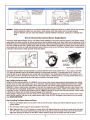
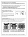
Inspect behind the bumper (fig. A.) in the approximate mounting area to check for any possible obstructions. For example check
for 5 miles per hour collision struts or hardened metal braces that could prohibit drilling.
Proper installation will take into consideration two factors:
1. Placement: height and distance either side of bumper center.
2. Angle: accurate detection depends on the correct sensor angle.
The sensor needs 1" clearance space behind the bumper to allow the
sensor to be fully inserted. Some bumpers have an outside cover or
fascia and a metal backing. You may have to drill through both layers
to insure you have enough clearance in order to install the sensors.
Other bumpers may require some removal of the foam backing.
CAUTION: Be Careful of hot exhaust parts and/or sharp edges
under bumper.
Determine the center of your bumper and mark the center using a grease pencil. Do not mount directly above exhaust pipe
opening. From the center of the bumper measure outward to the
location where you plan to mount your sensors. Mark the location with your grease pencil as
shown in Fig. B. Ideal Range From Bumper Center: 14" to 18". Sensors should be mounted
NO LOWER THAN 18" from the ground and NO HIGHER THAN 30’ (fig. C.). Using a grease
pencil, mark the final mounting location for the sensors.
NOTE: If bumper material is thicker than 5mm (0.2"), an external
bracket will be required to mount the sensors.
AS-RS
Reverse Scanning System
INSTALLATION MANUAL
FOR
Printed In USA 128-7073A
-1-


4. Determine where the sensor wires will enter into the trunk area or passenger compartment. Many vehicles have a factory
grommet to allow routing of wires from the outside to the inside of the vehicle. If you are drilling a hole through a metal body
panel to route your sensor wires into the trunk/cargo area, be sure to coat the holes edges with Zinc Galvanizer.
5. Feed the sensor wires through the factory grommet or other opening into the vehicle for connection to the control module
(e.g., into the cab of most trucks or the trunk of passenger cars). Finish by fitting the hole with a rubber grommet, or by
using automotive grade silicone to prevent moisture from entering the vehicle.
NOTE: Once the wires are passed through, ensure that you have the right amount of slack needed to route to the control
module. Make sure that the sensor wires will not be pinched by moving parts or panels.
6. Cable tie the sensor wires behind the bumper, away from any area that is close to the exhaust system or moving suspen-
sion parts. Do not pull or yank on the sensor wire were it exits the sensor shaft, as you may damage the inner connec-
tions.
7. Cover the sensor wires with split-loom for a factory appearance.
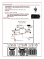
Mounting the Adjustable Piezo Speaker and Optional LED
The piezo speaker has three adjustment positions: Hi, Low and Off. Therefore, you need to mount the piezo speaker to the
vehicle interior where it can be easily accessed for adjustment.
1. Route the plugs for both the speaker and optional LED to the area where you will install the control module. Make sure that
they will not be pinched by any panels or moving parts.
2. Clean the piezo speaker back mounting area with the supplied alcohol pad, remove the backing strip from the Velcro and
firmly press the velcro pad onto the speaker back; then position the speaker into place on any fibrous cloth surface, or
mount with the screws supplied.
3. Attach the optional LED using the supplied brackets and double-sided adhesive foam pad , making sure it is in view
through the rear-view mirror, or rear center of the vehicle drivers line-of-sight.
NOTE: Do not mount speaker or optional LED in direct sunlight.
Mounting the control module.
Determine a dry place inside the vehicle (which will be out of the way) to mount the control module (e.g., behind an inner body
panel), making sure that all wiring will reach it’s intended location.
1. Plug the sensor wires, piezo speaker and power harness into the control module before mounting.
NOTE: The control module is pre-fitted with 3M Velco for mounting.
2. Clean the pre-selected mounting area with the alcohol pad provided to ensure good adhesion.
3. When surface is dry, peel off the backing of the Velco pad and stick the control module in place.
Connecting the Power Harness to the vehicle:
Determine where the reverse light wire is located. There are two methods of quickly and easily locating the reverse light power
wire:
CAUTION: Set the parking brake. The ignition key must be in the on position, but do not test with the engine running.
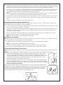
1. The first method is to actually remove the tail light housing from the vehicle. On many vehicles,
this can be done by simply removing 2 to 3 screws or bolts, and using light finger pressure.
to remove the assembly. Once the tail light housing is removed, examine where the wires plug in
to the back of the light housing. The target wire will have +12 volts when the vehicle is in the
reverse position, and 0 volts in any other gear position.
2. The second method also involves the use of a 12 volt multimeter. Probe the appropriate wiring
harness which heads toward the reverse light connector of the vehicle, looking for the wire which
carries +12 volts when reverse gear is engaged, and no voltage when reverse gear is disengaged.
Never use a test light to probe wires.
Once you have located the proper reverse light power wire, use pliers to connect the RED wire from
the unit’s power harness using the provided 3M Scotch-Lock connector. Make sure you have a solid
connection. A poor quality connection for power or ground may cause intermittent or no operation.
Connect the black, ground wire from the unit’s wiring harness to the vehicle’s chassis, using the
provided ring terminal connector, star washer and self-tapping screw.
-3-


© 2005 Audiovox Electronics Corp., Hauppauge, NY 11788
128-7073A
Printed in USA
-
 1
1
-
 2
2
-
 3
3
-
 4
4
-
 5
5
-
 6
6
-
 7
7
-
 8
8


Audiovox AS-RS User manual
- Category
- Motor vehicle electronics
- Type
- User manual
Ask a question and I''ll find the answer in the document
Finding information in a document is now easier with AI
Related papers
-
Audiovox ACAB104 Installation guide
-
-
-
-
-
-
-
-
-
Other documents
-
Advent PSS100 - Standard Rear Only System Installation guide
-
Chevrolet Impala SS User manual
-
 Code 3 Explorer/PIU Install Instructions
-
-
 Factory Five Racing Mk3 Roadster Assembly Manual
-
Factory Five Racing Mk4 Roadster Assembly Manual
-
Chrysler Intrepid User manual
-
Ford 2009 User manual
-
Jamo PRO-9642CH User manual
-
 Plymouth Stratus Repair manual


