Page is loading ...

User’s Guide
©2022 ROHM Co., Ltd.
1/4
No. 64UG036E Rev.002
Oct2022
ROHM Solution Simulator
905 nm Pulsed Laser Diode
RLD90QZWx series / Resonant wave B-01
This circuit simulate the resonant wave B-01 Time-Domain response of RLD90QZWx series. You can observe the resonant
wave of not only the current but also the optical output waveform. You can customize the parameters of the components shown
in blue, such as VIN, or peripheral components, and simulate the resonant wave B-01 Time-Domain with desired operating
condition.
General Cautions
Caution 1: The values from the simulation results are not guaranteed. Please use these results as a guide for your design.
Caution 2: Please refer to the Application note of Laser Diode for details of the technical information.
Caution 3: The characteristics may change depending on the actual board design and ROHM strongly recommend to
double check those characteristics with actual board where the chips will be mounted on.
1 Simulation Schematic
Figure 1. Simulation Schematic
2 How to simulate
The simulation settings, such as simulation time or convergence options, are configurable from the ‘Simulation Settings’
shown in Figure 2, and Table 1 shows the default setup of the simulation.
In case of simulation convergence issue, you can change advanced
options to solve. Default statement in ‘Manual Options’ is a sets the transient
analysis and parameter. You can modify it.
Figure 2. Simulation Settings and execution
Table 1. Simulation settings default setup
Parameters Default Note
Simulation Type Time-Domain Do not change Simulation Type
End Time 10 ns -
Advanced options
Balanced -
Time Resolution
Enhancement
Convergence Assist
-
Manual Options “.tran 0 10ns 0ns
.param VIN 90”
Default VIN for RLD90QZW3 is 60 V. RLD90QZW5
and RLD90QZW6 (30 V). RLD90QZW8 (90 V).
Simulation
Settings
Simulate

User’s Guide
RLD90QZWx series / Resonant wave B-01
No. 64UG036E Rev.002
Oct2022
©2022 ROHM Co., Ltd.
2/4
3 Simulation Conditions
Table 2. List of the simulation condition parameters
Instance
Name Type Parameters Default
Value
Variable Range Units
Min Max
V1 Voltage Source
Voltage_level VIN 1 190 V
AC_magnitude 0.0 fixed V
AC_phase 0.0 fixed ns
V2 Voltage Source
Initial_value 0 -5 3 V
Pulse_value 5 4 6 V
ramptime_initial_to_pulse 1n 1n 1µ s
ramptime_pulse_to_initial 1n 1n 1µ s
Start_delay 0 0 100 s
Pulse_width 30n 1n 1 s
Period 100µ 10n 1 s
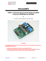
3.1 V2 parameter setup
Figure 3 shows how the V2 parameters correspond to the VIN stimulus waveform.
Figure 3. V2 parameters and its waveform
Start_delay
Period
Ramptime_initial_to_pulse
Pulse_value
Initial_value
Pulse_width
W
aveforms
record
ed
f
rom t=
0n
s
Ramptime_pulse_to_initial
Current
V
2
Optical
Output
Power
VIN pulsed
to GND

User’s Guide
RLD90QZWx series / Resonant wave B-01
No. 64UG036E Rev.002
Oct2022
©2022 ROHM Co., Ltd.
3/4
4 RLD90QZW8_Po model
Table 3 shows the model pin function implemented. Note that RLD90QZWx series_Po is the behavior model for its
optical output power response operation, and no protection circuits or the functions not related to the purpose are not
implemented.
Table 3. RLD90QZWx series_Po model pins used for the simulation
Pins Description
1 A / Anode
2 C / Cathode
OPT Optical output power in V [volts]
GND Ground
4.1 Optical Output Power
RLD90QZWx series_Po model outputs optical output power in V [volts] unit. Optical Output Power insert model
multiplies the output result by 1A and convert it to W [watts]. To monitor the optical output power in W [watts], select
probe item ‘power_output’ from property of Optical Output Power insert model.
Figure 4. Probe Items of Optical Output Power insert model

User’s Guide
RLD90QZWx series / Resonant wave B-01
No. 64UG036E Rev.002
Oct2022
©2022 ROHM Co., Ltd.
4/4
5 Peripheral Components
5.1 Bill of Material
Table 4 shows the list of components used in the simulation schematic. Each of the capacitor and inductor has the
parameters of equivalent circuit shown below. The default value of equivalent components are set to zero except for
the ESR of C, and parallel resistance of L. You can modify the values of each component.
Table 4. List of capacitors, inductors, and resistors used in the simulation circuit
Type Instance Name Default Value Variable Range Units
Min Max
Capacitor C2 1n 0.1n 10µ F
Inductor
L1 0.5 0.1 100 nH
L2 3 0.1 100 nH
L3 2 0.1 100 nH
Resistor R1 1k 0.1 10k Ω
R2 1.5 0.01 100 Ω
5.2 Capacitor Equivalent Circuits
(a) Property editor (b) Equivalent circuit
Figure 5. Capacitor property editor and equivalent circuit
The default value of ESR is 0.01 Ω.
5.3 Inductor Equivalent Circuits
(a) Property editor (b) Equivalent circuit
Figure 6. Inductor property editor and equivalent circuit
The default value of PAR_RES is 6.6 kΩ.
(Note 1) These parameters can take any positive value or zero in simulation but it does not guarantee the operation
of the IC in any condition. Refer to the datasheet to determine adequate value of parameters.
6 Link to the product information and tools
6.1 Laser Diode
RLD90QZW3 : 905 nm, 75 W, 225 μm Invisible Pulsed Laser Diode. [JP] [EN] [CN] [KR] [TW] [DE]
RLD90QZW5 : 905 nm, 25 W, 70 μm Invisible Pulsed Laser Diode. [JP] [EN] [CN] [KR] [TW] [DE]
RLD90QZW6 : 905 nm, 25 W, 50 μm Invisible Pulsed Laser Diode. [JP] [EN] [CN] [KR] [TW] [DE]
RLD90QZW8 : 905 nm, 120 W, 270 μm Invisible Pulsed Laser Diode. [JP] [EN] [CN] [KR] [TW] [DE]
Technical Articles and Tools can be found in the Design Resources on the product web page.

R1102
B
www.rohm.com
© 2016 ROHM Co., Ltd. All rights reserved.
Notice
ROHM Customer Support System
http://www.rohm.com/contact/
Thank you for your accessing to ROHM product informations.
More detail product informations and catalogs are available, please contact us.
Notes
The information contained herein is subject to change without notice.
Before you use our Products, please contact our sales representative
and verify the latest specifica-
tions :
Although ROHM is continuously working to improve product reliability and quality, semicon-
ductors can break down and malfunction due to various factors.
Therefore, in order to prevent personal injury or fire arising from failure, please take safety
measures such as complying with the derating characteristics, implementing redundant and
fire prevention designs, and utilizing backups and fail-safe procedures. ROHM shall have no
responsibility for any damages arising out of the use of our Poducts beyond the rating specified by
ROHM.
Examples of application circuits, circuit constants and any other information contained herein are
provided only to illustrate the standard usage and operations of the Products. The peripheral
conditions must be taken into account when designing circuits for mass production.
The technical information specified herein is intended only to show the typical functions of and
examples of application circuits for the Products. ROHM does not grant you, explicitly or implicitly,
any license to use or exercise intellectual property or other rights held by ROHM or any other
parties. ROHM shall have no responsibility whatsoever for any dispute arising out of the use of
such technical information.
The Products specified in this document are not designed to be radiation tolerant.
For use of our Products in applications requiring a high degree of reliability (as exemplified
below), please contact and consult with a ROHM representative : transportation equipment (i.e.
cars, ships, trains), primary communication equipment, traffic lights, fire/crime prevention, safety
equipment, medical systems, servers, solar cells, and power transmission systems.
Do not use our Products in applications requiring extremely high reliability, such as aerospace
equipment, nuclear power control systems, and submarine repeaters.
ROHM shall have no responsibility for any damages or injury arising from non-compliance with
the recommended usage conditions and specifications contained herein.
ROHM has used reasonable care to ensure the accuracy of the information contained in this
document. However, ROHM does not warrants that such information is error-free, and ROHM
shall have no responsibility for any damages arising from any inaccuracy or misprint of such
information.
Please use the Products in accordance with any applicable environmental laws and regulations,
such as the RoHS Directive. For more details, including RoHS compatibility, please contact a
ROHM sales office. ROHM shall have no responsibility for any damages or losses resulting
non-compliance with any applicable laws or regulations.
When providing our Products and technologies contained in this document to other countries,
you must abide by the procedures and provisions stipulated in all applicable export laws and
regulations, including without limitation the US Export Administration Regulations and the Foreign
Exchange and Foreign Trade Act.
This document, in part or in whole, may not be reprinted or reproduced without prior consent of
ROHM.
1)
2)
3)
4)
5)
6)
7)
8)
9)
10)
11)
12)
13)
/