
06-901 © S.R. Smith LLC 2008 JUN14
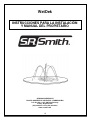
WetDek
CORPORATE HEADQUARTERS
WESTERN SALES AND MANUFACTURING PLANT
P.O. Box 400 ● 1017 SW Berg Parkway
Canby, Oregon 97013
(503) 266-2231 ● Fax (503) 266-4334
www.srsmith.com
INSTALLATION INSTRUCTIONS
AND OWNER’S MANUAL

2
INTRODUCTION
The WetDek is designed for use as a residential splash pad. Proper installation, use, and maintenance
are essential for optimal performance and to reduce the risk of accident or injury. These instructions are
developed and intended for use with either the stand alone or poolside versions of the WetDek with 6, 9,
or 12 nozzles.
WARNINGS
This unit must be hardwired only to a supply circuit that is protected by a ground
fault circuit interrupter (GFCI). Such a GFCI is required by most building codes and should be
provided by the installer, and must be tested before each use. Consult GFCI manufacturers’ instructions
for correct testing and operation. A bonding lug has been provided on the outside of the electrical control
box. The lug permits the connection of No. 8 AWG solid copper bonding conductor between the controller
and all other electrical equipment and exposed metal in the vicinity. ALL ELECTRICAL CONNECTIONS
MUST COMPLY WITH NATIONAL ELECTRIC CODE, AS WELL AS ANY APPLICABLE LOCAL
CODES. A LICENSED ELECTRICIAN MUST BE USED FOR ALL ELECTRICAL CONNECTIONS.
The custom circuit board in the WetDek AquaDirector Controller has been tested before leaving
the manufacturing plant. A BLOWN CIRCUIT BOARD IS NOT COVERED UNDER THE WARRANTY
OF THIS PRODUCT. It is important to have a licensed electrician install the AquaDirector. Also, it is
important that they read the instructions provided here and the wire diagram in the controller to insure that
the circuit board is not damaged.
DANGER – RISK OF ELECTRICAL SHOCK. Install at least 5 feet (1.5m) away from all metal
surfaces. A WetDek may be installed within 5 feet of metal surfaces if each metal surface is permanently
connected by a minimum No. 8 AWG solid copper conductor that is bonded to the control box. Do not
permit any electrical appliance such as a light, telephone, radio, or television within 5 feet (1.5m)
of a WetDek.
EXTREME CAUTION – adult supervision required during use. Do not leave
children unattended around the WetDek. To avoid accidents and injury, insure that children
cannot use the Wetdek unless they are supervised by a responsible adult at all times. Do not use the
WetDek if the drain cover or nozzles are broken or malfunctioning in any way. A broken drain cover can
cause severe injury so examination of drain before each use is critical. Insure before use that drain cover
is secured and that drain is functioning properly. Note: the WetDek is not intended to be a wading pool of
any sort; do not allow use if pooling or back up of water occurs.
CHEMICAL SAFETY – Play it safe with chemicals. Maintain sanitizer level of 3-5 ppm of
bromine or chlorine. There is risk of illness if the water is not properly sanitized. Follow all chemical
manufacturers’ recommendations to insure proper sanitation. Always store chemicals according to the
manufacturer’s label directions and keep them out of reach of children. The stand alone model reservoir
should be emptied at least every two months.
**IMPORTANT**
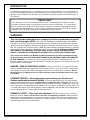
Check entire box and inside all packing materials for parts. Before beginning assembly, read the
instructions and identify parts using the figures and parts listed in this document. It is critical that all
parts be carefully inspected by the installer prior to installation to ensure that no damage occurred in
transit and that a damaged part is not used. Proper installation cannot be overstressed, as improper
installation voids S.R. Smith’s warranty and may affect the safety of the user.

3
(1)
(2)
(3)
(4)
(5)
(7)
(9)
(10)
(6)
(8)
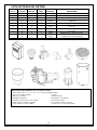
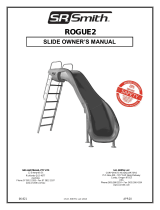
WETDEK PARTS LIST
Poolside
Stand Alone
ITEM NO.
QTY.
PART NO.
DESCRIPTION
X
X
1
1
30011
WetDek AquaDirector Controller
X
X
2
6, 9, 12
31000
Brass Nozzles
X
X
3
4
30005
1” HPV Valves
X
X
4
4
30006
1” Valve Manifold Tee
X
X
5
1
30007
1” Globe Valve
X
X
6
1
30013
8” Drain w/ 6” ABS Hub
X
X
7
1
30014
6” ABS to 4” PVC Converter
X
8
1
30001
¾ HP Pump
X
9
1
30015
25sf Filter Housing/Chlorinator
X
10
1
30004
150 Gallon Reservoir w/ Fittings
ITEMS NEEDED FOR INSTALLATION
1) PVC Pipe (4”, 1.5” and 1”, length varies) 8) Level
2) PVC Fittings (Varies) 9) PVC Saw
3) PVC Primer 10) Wire Cutters
4) PVC Glue 11) Tape Measure
5) 8 AWG Copper Bonding Wire 12) Valve Box (optional)
6) 16 AWG Electrical Wire (Valves) 13) 1” Spigot (optional)
7) 8 AWG Electrical Wire (Pump)

4
WETDEK INSTALLATION GUIDELINES
The WetDek can be installed as a stand alone product or as a poolside feature. Each model requires
variations in installation. There is also a section of common installation requirements and a section for
optional additions that can be added to the system.
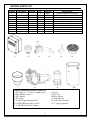
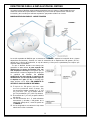
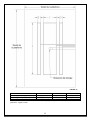
BACKYARD STAND ALONE MODEL
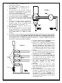
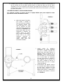
The stand alone version of the WetDek, shown in FIGURE 1, requires the installation of a dependent
pump and filtration system, as well as the placement of a 150 gallon reservoir. This is in addition to the
valve manifold, control box, and spray pad area that are required for all WetDeks.
Because the WetDek is based upon a
gravity drain, the top of the reservoir must be
located at least 6 inches lower than the drain.
This means that the reservoir should either be
positioned below ground level or placed downhill
from the WetDek surface (if the tank is located
underground, DO NOT BACKFILL AROUND
OR ON TOP OF THE TANK WITHOUT
PROPER REINFORCEMENT OR TANK MAY
COLLAPSE). The maximum change in height
from the WetDek surface to the standing
level of water in the reservoir is 5 feet; if more
height is required contact S.R. Smith. DO NOT
HOOK THE WETDEK UP TO A SUCTION
RETURN.
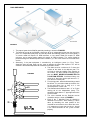
1. The 150 Gallon Reservoir (10) has four
fittings that are pre-attached to the tank.
There are three 1 ½” female threaded
fittings and one 4” female threaded fitting.
The dimensions for the tank are as follows:
32” diameter, 51” height.
2. The 4” fitting is designated for the drain line.
3. The three 1 ½” fittings are in-line with each
other, and are located 90 degrees from the
4” drain line, as shown in FIGURE 2.
FIGURE 1
FIGURE 2

5
4. The lowest fitting is designated for the
suction line to the pump.
5. The middle fitting is designated for the
recirculation/bypass line returning from the
valve manifold.
6. The top fitting on the reservoir should be
connected as an overflow pipe or as an auto-fill.
If used as an overflow pipe, it should run to a
French drain or other overflow area.
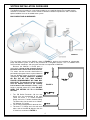
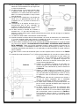
7. The ¾ HP Pump (8) and 25sf Filter/Chlorinator
(9) should be setup as shown in FIGURE 3.
8. The ¾ HP Pump (8) and 25sf Filter/Chlorinator
(9) require 1 ½” PVC pipe for both inlet and
outlet.
9. The inlet of the pump should be connected to
the lowest 1 ½” fitting on the reservoir; the
maximum height for the self-priming pump
above the waterline in the reservoir is 7 ft.
10. The pump outlet should run directly to the
filter/chlorinator.
11. From the filter/chlorinator to the valve manifold
the pipe should stay at 1 ½” as long as possible
to reduce pressure loss in the pipe, but it needs
to be scaled down to 1” before the valve
manifold.
12. The pump for the stand alone version of the WetDek should be wired directly to the control box that
comes with the WetDek. THIS CONNECTION MUST BE DONE BY A LICENSED ELECTRICIAN.
This will regulate when the pump runs in unison with the valves. The pump and controller run off of a
115 Volt power source. The WetDek AquaDirector Controller (1) is rated as a NEMA 3R enclosure,
which allows it to be placed indoors or outdoors. 13. The valve manifold for the Stand Alone version
should be setup as shown in FIGURE 4.
14. Each of the 1” Manifold Tees (4) should be
attached to one of the 1” HPV Valves (3). This is
done by threading the male portion of the
manifold tee to the female inlet side of the valve.
It is important to insure that the valve is placed
in the correct direction for the system to work
properly.
15. It is also important to insure that the valves are
all in the same orientation before attaching the
Manifold Tees (4) as shown in FIGURE 4.
16. The Manifold Tees (4) should first be wiped with
a PVC Primer and then given a liberal amount of
PVC Glue on one of the surfaces before
connecting the male and female ends.
17. The first three valves will each connect to one of
the zones controlled by the WetDek
AquaDirector Controller. The order is not
important.
18. The fourth valve will control the daily
recirculation function that is vital for the Stand
Alone version of the WetDek to insure that the
water remains clean.
19. The last portion of the valve manifold should
connect the 1” Globe Valve (5) from the end of
the valve manifold to the same line as the
recirculation line, as shown in FIGURE 4. This
will work as a bypass and will allow you to
manually adjust the heights of the water spray
for the whole system.
FIGURE 4
FIGURE 3

6
POOLSIDE MODEL
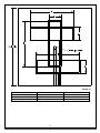
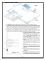
1. The proper layout for the WetDek poolside plumbing is located in FIGURE 5.
2. The poolside version of the WetDek should run off of an independent pump from the rest of the
pool. This independent pool pump will need to provide the following gallons per minute (GPM): a
six nozzle model will require 18 GPM minimum, a nine nozzle model will require 27 GPM
minimum, and a twelve nozzle model will require 36 GPM minimum. This pump should be
powered through the WetDek AquaDirector Controller (1) in the same manner as the Stand Alone
version.
3. Alternately, if the pool equipment is controlled by an intelligent system (i.e. Easy Touch,
AquaLink) then the pool pump can be setup to provide the water flow required. This will be
covered in the WetDek AquaDirector Controller Installation section.
4. The drain must be a minimum of 6” above the
surface of the water in the adjacent pool. This
will help to eliminate puddles from forming on
the surface. The drain should run directly to the
pool and MUST NEVER BE CONNECTED TO
A SUCTION RETURN. If bulkhead fittings are
used, the 4” drain line can be split into two 1 ½”
lines that run into the pool.
5. For existing pools, where bulkhead fittings would
be difficult, it is possible to hook up the drain line
to the pool return line as long as it is not
connected to the suction side.
6. The WetDek should have its own 1 ½” or 2” pipe
coming off of the independent pump. This
should be sized down to 1” pipe right before the
valve manifold.
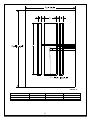
7. The valve manifold for the Poolside version
should be setup as shown in FIGURE 6.
8. Each of the 1” Manifold Tees (4) should be
attached to one of the 1” HPV Valves (3). This is
done by threading the male portion of the
manifold tee to the female inlet side of the valve.
It is important to insure that the valve is placed
in the correct direction for the system to work
properly.
FIGURE 5
FIGURE 6

7
9. It is also important to insure that the valves are all in the same orientation before attaching the
Manifold Tees (4) as shown in FIGURE 6.
10. The Manifold Tees (4) should first be wiped with a PVC Primer and then given a liberal amount of
PVC Glue on one of the surfaces before connecting the male and female ends.
11. The first three valves will each connect to one of the zones controlled by the WetDek
AquaDirector Controller. The order is not important.
12. The last portion of the valve manifold should connect the 1” Globe Valve (5) from the end of the
valve manifold back to the pools return line, as shown in FIGURE 6. This will work as a bypass
and will allow you to manually adjust the heights of the water spray for the whole system.
COMMON INSTALLATION INSTRUCTIONS
1. The nozzles can be placed in any of the examples presented in the WETDEK CONFIGURATION
EXAMPLES & GUIDELINES section. Please note: all nozzles must be approximately the
same distance from the valves to assure that the height of the water streams remains
constant.
2. The slope of the surface needs to have a minimum two degree slope toward the drain. This
means that for every foot of radius there needs to be a quarter inch drop, e.g. 14 ft. diameter pad
means a 7 ft. radius, so the pad should drop 1 ¾ in. from the edge of the pad to the drain.
20. The nozzles must be at least two feet from the edge of the pad to prevent overspray. The nozzles
have adjustable ball valves that can be aimed in any direction, up to 60 degrees.
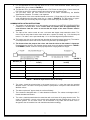
21. The distance from the pump to the valves and from the valves to the nozzles is important.
Depending on the distance, the diameter of pipe needs to vary for optimal performance. TABLE 1
and FIGURE 7, below, show the size of pipe required for varying distances of pipe.
Distance (Ft)
Pump to Valves (Pipe Diameter in
Inches)
Valves to Nozzles (Pipe Diameter in
Inches)
50
1.5
1
100
1.5
Not Recommended
150
2
Not Recommended
200
2
Not Recommended
250
Not Recommended
Not Recommended
5. The valves should be placed either in the pump house or in a valve box near the intended
WetDek surface. The valves can only be placed in a pump house if the pad is within 50 feet of the
WetDek surface.
6. The drain requires a 4” pipe to drain the surface efficiently.
7. The nozzles are designed with a 1” male threaded connection. The valves are designed with 1”
female threaded connections.
8. The valves should be attached to the control box with a minimum of 16 gauge electrical wire. The
valves are 24 Volt AC, so each valve needs to be attached with two separate wires; there is no
common ground. The first three valves can be attached in any order, but the fourth valve is
designed as the recirculation line and should be attached accordingly.
TABLE 1 – Maximum Pipe Distance due to Viscosity
FIGURE 7

8
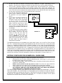
OPTIONAL INSTALLATION ADD-ONS
The following items are not provided with your WetDek kit but can be purchased additionally from
many local suppliers.
1. ADDITIONAL GLOBE
VALVES: To help
control the height of
each individual zone it
is required that a 1”
Globe Valve (5) be
placed after each 1”
HPV Valve (3) as
shown in FIGURE 8.
This allows the WetDek
to be customized even
more. Water heights
can be set to the exact
same level or setup on
a tiered system that
separates each zone by
measured increments.
2. SPIGOT FOR STAND
ALONE: A spigot can be
incorporated in the stand
alone version of the WetDek
to allow for draining the
reservoir, as shown in
FIGURE 9; this spigot
should be located between
the pump (8) and
filter/chlorinator (9). The
spigot must be easily
accessible to allow for
connection to a hose. No
spigot is required for the
poolside version because
the pool will have its own
drain system.
3. UNION FITTINGS: It is also
a good idea to use union
fittings before and after
each piece of equipment
used in the WetDek system
to allow for easy repair or
replacement. This is also
shown in FIGURE 9.
4. AUTO-FILL: Another optional
item for the Stand Alone version
of the WetDek, an Auto-Fill can
be attached to the top 1 ½”
FIGURE 8
FIGURE 9

9
fitting on the Reservoir to
regulate the water level in the
tank, as shown in FIGURE 10.
This is recommended for
WetDeks located in hot climates
where evaporation will have a
greater effect on water levels.
5. VALVE BOX: If the valve
manifold needs to be moved
closer to the pad because of
distance requirements
(maximum distance from the
valve manifold to furthest nozzle
is 50’), it is recommended that
the valves be buried and placed
in a standard green valve box
used for sprinkler systems. This
can be used for either the Stand
Alone or Poolside versions.
WETDEK AQUADIRECTOR CONTROLLER INSTALLATION
The WetDek System Controller requires an onsite licensed electrician to install. These guidelines
should be used to insure that the controller has been installed properly.
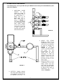
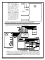
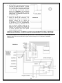
1. FIGURE 11 shows the internal wiring for the WetDek AquaDirector Controller. The WetDek controller
is manufactured to handle 120V input; this diagram shows how to install the standard configuration
for 120V power. Please read this section carefully to prevent damage to the circuit board. All
circuit boards are tested twice before they leave our shop to insure that they are operational. A blown
circuit board is not covered under warranty.
FIGURE 10
FIGURE 11

10
2. All wires that enter the controller should be placed in NEMA-3R, or higher, rated fittings. For UL
purposes, the electrician installing the controller must drill these holes onsite and place the fittings.
3. The first wires connected should run to the solenoid valves and recirculation lines. These wires
connect to the Printed Circuit Board, and are labeled as follows: SOL1, SOL2, SOL3, RECIRC. The
valves are 24V AC, which means that each valve needs two wires to run directly from the board to the
valve. There will not be a common wire used for the valves. If the solenoid valve wires are touching
this will cause continuance in the circuit and will blow the circuit board.
4. The next item connected should be the
pump, and this should be connected to
the contactor in the inputs labeled T1
and T3.
5. The last wires connected should be the
power wires, and these run to the
contactor as well but on the side labeled
L1 and L2. (There are already black
wires running to L1 and L2, but the
power should be wired next to these
wires.) If you use a 240V power source
on the system as manufactured you will
overload the transformer and blow the
circuit board.
6. It is possible to run the system at 240V if
you are using a pump that requires this
much voltage. To do this you must
switch the wire that runs from the
contactor to the terminal block, as
shown in FIGURE 12. This wire needs
to be moved to the terminal that reads
240V on the terminal block. This should
be done before any other wiring is
attached to the controller.
The WetDek AquaDirector can be hooked up to a pool control system, such as the Easy Touch or Aqua
Link. This is accomplished by powering the AquaDirector from one of the free relays on the pool control
system. It is important to follow all of the installation guidelines in this section to avoid damaging the
AquaDirector. If attached to a pool control system, it is possible to run the pump through the pool control
system instead of the AquaDirector, but it is important to insure that the pump cannot be running when
the AquaDirector has stopped running. The AquaDirector is designed to default to an ON position for 30
minutes every time power is returned to the system. It will also remember the last program that was used.
If the pump is setup independently of the AquaDirector, it should be placed on a timer that shuts the
pump off after 30 minutes to prevent damaging a component of the system (i.e. pump, valves, etc…).
WETDEK CONFIGURATION EXAMPLES & GUIDELINES
When building your WetDek configuration, follow these guidelines for best results.
1. All piping from valve to nozzle should be approximately the same length. This will insure that
the water shoots equally from each nozzle.
2. To avoid forming puddles, make sure that the drain is located at the lowest point and that the
surface has a steady slope.
3. Nozzles must be placed so that top surface is level. The surface can slope around the
nozzle, and the ball on the nozzle can be adjusted to aim the water after installation.
4. Surface options are up to the installer; we recommend using stamped or brushed concrete.
ANY SURFACE USED WITH THE WETDEK MUST MEET ANY LOCAL OR NATIONAL
CODES FOR NON-SLIP SURFACES AND HEALTH SAFETY.
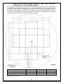
The following images show the pipe layouts for the nozzles for various pad configurations. These are
some stock examples, but custom designs are encouraged to give each project a unique feel. Nozzles
should be divided evenly amongst the three zones (Two nozzles per zone for a 6 nozzle kit, three nozzles
per zone for a 9 nozzle kit, and four nozzles per zone for a 12 nozzle kit). Nozzles can be placed
anywhere on the loop to allow for maximum customization.
FIGURE 12

11
PAD SIZE
A*
B*
C*
11’ Diameter (6 Nozzles)
84
48
24
13’ Diameter (9 Nozzles)
108
72
36
15’ Diameter (12 Nozzles)
132
96
48
TABLE 2 *All dimensions given in inches
FIGURE 13

12
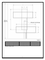
PAD SIZE
A*
B*
12’ x 12’ (6 Nozzles)
24
84
14’ x 14’ (9 Nozzles)
36
108
16’ x 16’ (12 Nozzles)
48
132
TABLE 3 *All dimensions given in inches
FIGURE 14

13
PAD SIZE
A*
B*
C*
12’ x 8’ (6 Nozzles)
96
6
24
14’ x 10’ (9 Nozzles)
120
12
36
16’ x 12’ (12 Nozzles)
144
18
48
TABLE 4 *All dimensions given in inches
FIGURE 15

14
OPERATING THE CONTROLLER
The control box that operates the WetDek has three buttons, which are used to control the system, and
four lights, as well as a four digit numerical display. The three buttons are labeled “Sel”, “Inc/+”, and
“Dec/-“. The four lights are labeled “Program Select”, “Run Time”, “Recirc Start”, and “Time of Day”.
Buttons
Sel This button allows you to change between the different light functions.
Inc/+ This button will increase the variable on the numerical display by one. To
increase time quickly, press and hold the button down
Dec/- This button will decrease the variable on the numerical display by one. To
decrease time quickly, press and hold the button down
Lights
Program Select There are five programs to choose in the “Program Select” light, numbered 1-5:
program 1 is a set pattern of one zone at a time with variable timeframes,
program 2 is a set pattern of two or three zones for variable timeframes, program
3 is a randomized spray of variable time, program 4 is all of the jets spraying
continuously, and program 5 cycles through all four of the other programs.
Run Time The run time can be set from 1 minute to 23 hours and 59 minutes. The system
will shut itself off after the time frame has elapsed.
Recirc Start The start time for the recirculation function of the control box. It is meant to
control the fourth solenoid valve and determines what time of day that it should
run at. Generally, you would pick a time when the system would not normally be
running because it will take away from the overall performance of the WetDek.
Recirculation is only required on Stand Alone versions of the WetDek.
Time of Day Time of Day is set as a reference for the recirculation line and should remain
constant, even if the box is unplugged because a battery is present to run the
clock.
COMMONLY ASKED QUESTIONS
1. How do you hook up the controller to Pentair, Jandy and Hayward controllers? Just one power
cord going from the SRS box to the controller. It will only use one relay on the automation system and
will only control turning the box on/off.
2. What size pump is required for the pool kit version? The builder should know the capabilities of
the preexisting equipment. The size of the pump and filter will always be determined by the hydraulics
and the body of water. Things like how far away the equipment is, to plumbing size or number of
fittings, can determine this.
3. How thick should the concrete slab be? Should rebar be used? The concrete slab should be 4”
thick, and does not require rebar (although some local codes might require that rebar be used). The
nozzles need to be grounded so this will help; otherwise, copper wire must be connected from each
of the nozzles to a grounding point.
4. What should the slab size be for either a square or round pad for each unit? What about
different shape slab; will SRS help with jet and drain placement? For a 6 nozzle WetDek the
recommended minimum size is either an 11’ diameter circle or a 12’ x 12’ square. This is to minimize
the amount of water lost. Obviously someone could put it in a smaller pad, but an auto-fill would
become a necessity and other issues could come up, so we do not recommend using a smaller pad.
SR Smith can help design custom pads but the customer will be charged for this service.
5. How to keep water from entering the drain in the winter? The easiest way to do this would be to
keep the cover (which is plastic) or use a similar material and place it under the grate and tighten it in
place.
6. Can the nozzles be placed in the deck of a new pool and shoot water into the pool? Yes, there
are endless possibilities for location of the nozzles and this one simplifies the process because of the
removal of a drainage system.
7. How long does it take to complete the whole job on a stand alone with 6 nozzles? Generally 3
days but after completing a few units this should be reduced to 1.5 to 2 days.

15
WETDEK CARE & MAINTENANCE
There are a couple of areas of the WetDek that require regular maintenance: water, plumbing, and the
pump. Routine checks will help prolong the life of all components of the WetDek.
WATER TESTING
It is recommended that you test your WetDek water regularly with an accurate test kit or test strips. These
are available from your local Pool & Spa Dealer. Also, be sure to follow chemical manufacturers’
instructions for chemical use.
pH CONTROL
All water solutions have pH, which is a measure of the acid to base relationship. A pH reading of 7.0 is
neutral, a lower reading is acidic and a higher reading is basic. The proper pH for WetDek water is
between 7.4 and 7.6 High pH (above 7.6) can reduce sanitizer efficiency, cloud the water, promote scale
formation on surfaces and equipment, and interfere with filter operations. When pH is too high, add a pH
decreaser. Low pH (below 7.2) is equally damaging and can cause equipment corrosion, water that is
irritating, and rapid sanitizer dissipation. Add pH increaser to bring the pH higher.
It is important to use scale and stain inhibitor weekly to prevent calcium deposits from damaging your
WetDek and equipment. If this happens, it could void the warranty. Refer to your chemical handbook for
further information on water chemistry and troubleshooting.
DRAINING THE WATER
Locate the spigot between the chlorinator and valve manifold. Attach a garden hose and open the valve.
The controller should be set to recirculation during draining. Any water that the pump does not remove
should be sucked out with a wet/dry vacuum.
FILTER MAINTENENCE
At least once a month, (or more often based on environmental conditions) check and clean the skimmer
basket of the pump to ensure proper flow. Remove leaves, foreign matter and debris when present. It is
also very important to maintain your WetDek filter cartridge clean and free of particles that can obstruct
water flow. A clean filter will permit the system to function properly and also allows more efficient filtering.
Depending on how frequently your WetDek is used, we recommend cleaning the WetDek filter cartridge
every four to six weeks. If this is not done, the filter may clog and restrict water flow, which causes
inadequate filtration and poor nozzle performance.
CLEANING THE FILTER
Carefully pull up the filter cartridge and bring it out of the WetDek. Rinse cartridge using a garden hose.
Rotate and separate filter pleats while spraying water to remove all debris possible. Let the filter dry and
look for calcium deposits (scaling) or an oil film. If you find these, you will need to deep clean your filter
cartridge with a “spa filter cleaning” solution to break down and remove mineral deposits and oils.
WINTERIZATION
You must winterize the WetDek when freezing temperatures are expected or if prolonged periods without
use are expected; this will help protect all components. Water should be drained from the reservoir in the
stand alone model, and water should be cleared from the pump, filter, chlorinator, and all piping. The balls
in the nozzles should be rotated so that no water can drain into them, and then tightened.
IMPORTANT
PERSONALLY GIVE TO OWNER THIS WETDEK OWNER’S MANUAL, THE
WARRANTY CARD AND ANSWER ALL QUESTIONS.

16
WetDek
OFICINAS GENERALES
PLANTA OCCIDENTAL DE VENTAS Y FABRICACIÓN
P.O. Box 400 ● 1017 SW Berg Parkway
Canby, Oregon 97013
(503) 266-2231 ● Fax (503) 266-4334
www.srsmith.com
INSTRUCCIONES PARA LA INSTALACIÓN
Y MANUAL DEL PROPIETARIO

17
INTRODUCCIÓN
El WetDek ha sido construido para utilizarse como una atracción acuática residencial para chapotear. Su
instalación, utilización y mantenimiento correctos son esenciales para que funcione óptimamente y
disminuya el riesgo de un accidente o una lesión. Se redactaron estas instrucciones para utilizarse ya
sea con la plataforma sola o con las versiones del WetDek con 6, 9, ó 12 boquillas para instalarse al lado
de la alberca.
ADVERTENCIAS
Se debe conectar esta unidad únicamente a un circuito de suministro protegido con un
interruptor de circuito sin conexión a tierra (GFCI, por sus siglas en inglés). La mayoría de
los códigos de construcción requieren tal GFCI, el cual debe ser provisto por el instalador y probado
antes de cada uso. Consulte las instrucciones de los fabricantes de los GFCI para probarlos y operarlos
correctamente. Se ha incluido una aleta de conexión en el exterior de la caja eléctrica de control. La aleta
permite conectar el conductor de conexión de cobre sólido No. 8 AWG entre el controlador y todo el otro
equipo eléctrico y metal expuesto en los alrededores. TODAS LAS CONEXIONES ELÉCTRICAS
DEBEN CUMPLIR CON EL CÓDIGO ELÉCTRICO NACIONAL Y CON TODOS LOS CÓDIGOS
LOCALES PERTINENTES. DEBE CONTRATARSE A UN ELECTRICISTA PROFESIONAL
AUTORIZADO PARA QUE REALICE TODAS LAS CONEXIONES ELÉCTRICAS.
Se ha probado el tablero del circuito hecho a la medida del Controlador AquaDirector del WetDek
antes de salir de la planta manufacturera. LA GARANTÍA DE ESTE PRODUCTO NO CUBRE UN
TABLERO DEL CIRCUITO QUEMADO. Es importante que un electricista profesional autorizado instale
el AquaDirector y que se lean las instrucciones proporcionadas aquí y el diagrama de los cables en el
controlador para asegurarse de que el tablero del circuito no haya sido dañado.
PELIGRO – RIESGO DE CHOQUE ELÉCTRICO. Instale la unidad por lo menos a 5 pies (1.5
m) de distancia de toda superficie metálica. Un WetDek puede instalarse a 5 pies o menos de superficies
metálicas si cada una de ellas está conectada permanentemente por un conductor de cobre sólido (No. 8
AWG como mínimo) que va conectado a la caja de control. No permita que haya ningún aparato
eléctrico como lámpara, teléfono, radio o televisión a 5 pies (1.5 m) o menos de un WetDek.
PRECAUCIÓN EXTREMA – la supervisión adulta es obligatoria durante el uso. No
deje a los niños alrededor del WetDek sin atenderlos. Para evitar accidentes y lesiones,
cerciórese de que los niños no puedan utilizar el WetDek a menos que estén siendo supervisados por
un adulto responsable en todo momento. No use el WetDek si la cubierta del drenaje o las boquillas
se han roto o funcionan mal de la manera que sea. Una cubierta rota del drenaje puede causar lesiones
graves por lo que es esencial revisarla antes de cada uso. Antes el uso, asegúrese que la cubierta del
drenaje esté fija y que el drenaje funcione debidamente. Nota: el WetDek no se construyó para ser
ningún tipo de alberca para niños; no permita su uso si se forma un estanque o si se acumula el agua.
SEGURIDAD QUÍMICA – cuídese de las sustancias químicas. Mantenga la
concentración del desinfectante de 3 a 5 ppm de bromo o cloro. Hay riesgo de enfermedad si el agua
no ha sido debidamente desinfectada. Siga todas las recomendaciones de los fabricantes químicos
para asegurar la desinfección adecuada. Siempre almacene las sustancias químicas conforme a las
indicaciones de la etiqueta del fabricante y déjelas fuera del alcance de los niños. Se debe vaciar el
depósito del modelo separado por lo menos cada dos meses.
**IMPORTANTE**
Revise toda la caja y el interior de los materiales del empaque para encontrar las piezas. Antes de
comenzar con el ensamblado, lea las instrucciones e identifique las piezas consultando las figuras y
las piezas enumeradas en este documento. Es esencial que el instalador inspeccione todas las piezas
detenidamente antes de la instalación para asegurar que no se hayan dañado en tránsito y que no se
utilice una pieza dañada. Hacemos mucho hincapié en la instalación correcta, ya que una instalación
indebida anula la garantía de S.R. Smith y podría afectar la seguridad del usuario.

18
LISTA DE PIEZAS DEL WETDEK
Junto a la
alberca
Separado
NO. ART.
CANT.
PIEZA NO.
DESCRIPCIÓN
X
X
1
1
30011
Controlador AquaDirector del WetDek
X
X
2
6, 9, 12
31000
Boquillas de latón
X
X
3
4
30005
Válvulas HPV de 1” (2.54 cm)
X
X
4
4
30006
Accesorio en T de 1” (2.54 cm) de la válvula de
distribución
X
X
5
1
30007
Válvula de globo de 1” (2.54 cm)
X
X
6
1
30013
Drenaje de 8” (20.3 cm) con cubo ABS de 6”
(14.2 cm)
X
X
7
1
30014
Convertidor del ABS de 6” (15.2 cm) a PVC de
4” (10.2 cm)
X
8
1
30001
Bomba de ¾ de caballos de fuerza
X
9
1
30002
Cubierta del filtro/Clorinador para 25 pies
cuadrados (2.3 metros cuadrados)
X
10
1
30004
Depósito de 150 galones (567.8 l) con accesorios
(1)
(2)
(3)
(4)
(5)
(6)
(7)
(8)
(9)
(10)
ARTÍCULOS NECESARIOS PARA LA INSTALACIÓN
1) Tubo de PVC (de 4”, 1.5” y 1” (10.1, 3.8 y 2.54 cm) la longitud varía)
2) Accesorios de PVC (varían) 8) Nivel
3) Tapaporos para PVC 9) Sierra de PVC
4) Pegamento para PVC 10) Tenazas corta alambres
5) Alambre de conexión de cobre 8 AWG 11) Cinta para medir
6) Cable eléctrico (válvulas) 16 AWG 12) Caja de la válvula (opcional)
7) Cable eléctrico (bomba) 8 AWG 13) Llave de 1” (2.54 cm) (opcional)

19
DIRECTRICES PARA LA INSTALACIÓN DEL WETDEK
Se puede instalar el WetDek como producto separado o junto a la alberca. Cada modelo tiene una
manera de instalación un poco distinta. También hay una sección de requerimientos comunes de
instalación y otra sección para adiciones opcionales que pueden añadirse al sistema.
MODELO SEPARADO PARA EL JARDÍN TRASERO
La versión separada del WetDek que se muestra en la FIGURA 1 requiere la instalación de un sistema
dependiente de bombeo y filtración así como la colocación de un depósito de 150 galones (567.8 l)
además de la válvula de distribución, la caja de control y el área para la plataforma para salpicar que
requieren todos los WetDeks.
Ya que el WetDek funciona con drenaje por
gravedad, se debe colocar la parte superior del
depósito por lo menos 6 pulgadas (15.2 cm)
más abajo que el drenaje. Esto significa que se
debe enterrar o colocar el depósito más abajo que
la superficie del WetDek. La máxima
modificación de altura desde la superficie del
WetDek hasta el nivel estacionario del agua en
el depósito es 5 pies (1.5 m); si necesita más
altura, diríjase a S.R. Smith. NO CONECTE EL
WETDEK A UNA SUCCIÓN DE RETORNO.
22. El depósito de 150 galones (10) tiene cuatro
accesorios previamente unidos al tanque. Hay
tres accesorios hembra roscados de 1 ½” (3.8
cm) y uno de 4” (10.1 cm). El tanque mide 32”
(81.3 cm) de diámetro y 51” (129.5 cm) de altura.
23. El accesorio de 4” (10.1 cm) es para la tubería
del drenaje.
24. Los tres accesorios de 1 ½” están alineados
mutuamente y ubicados a 90 grados de la
tubería del drenaje de 4”, como se aprecia en
la FIGURA 2.
25. Se ha designado el accesorio más bajo como
tubería de succión a la bomba.
FIGURA 1
FIGURA 2

20
26. Se ha designado el accesorio central para la
tubería de recirculación/desvío que regresa de
la válvula de distribución.
27. Se debe conectar el accessorio superior sobre
el depósito como tubo de derrame o llenado
automático. Si se utiliza como tubo de derrame,
debe ir a un drenaje de piedra en zanja o a otra
área de derrame.
28. Se debe instalar la bomba de ¾ de caballos de
fuerza (8) y el filtro/clorinador para 25 pies
cuadrados (2.3 m2) (9) como se muestra en la
FIGURA 3.
29. La bomba de ¾ de caballos de fuerza (8) y el
filtro/clorinador para 25 pies cuadrados (9)
requieren un tubo de PVC de 1 ½” (3.8 cm)
tanto para la entrada como para la salida.
30. Se debe conectar la entrada de la bomba al
accesorio de 1 ½” que está más abajo en el
depósito; la altura máxima para la bomba autocebante por encima del nivel del agua en el depósito
es de 7 pies (2.1 m).
31. La salida de la bomba debe ir directamente al filtro/clorinador.
32. Se debe mantener la tubería desde el filtro/clorinador a la válvula de distribución en un tamaño de 1
½” la mayor longitud posible para disminuir la pérdida de presión en la tubería, pero se necesita
reducir a 1” (2.54 cm) antes de llegar a la válvula de distribución.
33. Se debe cablear la bomba para la versión separada del WetDek directamente a la caja de control
que viene con el WetDek. UN ELECTRICISTA PROFESIONAL AUTORIZADO DEBE REALIZAR
ESTA CONEXIÓN. Tendrá una función reguladora cuando la bomba trabaje al unísono con las
válvulas. La bomba y el controlador funcionan con una fuente de poder de 115 voltios. Ya que el
controlador AquaDirector del WetDek (1) está aprobado para cobertura NEMA 3R, puede colocarse
afuera o adentro.
34. Se debe instalar la válvula de distribución para la versión separada como se muestra en la FIGURA
4.
35. Se debe fijar cada accesorio en T de 1” (2.54 cm) de la distribución (4) a una de las válvulas HPV de
1” (3). Esto se hace enroscando la parte macho del
accesorio en T de la distribución al lado de la entrada
hembra de la válvula. Es importante asegurarse de
colocar la válvula en la dirección correcta para que el
sistema funcione debidamente.
36. También es importante cerciorarse de que todas las
válvulas tengan la misma orientación antes de fijar los
accesorios en T de la distribución (4) como se muestra en
la FIGURA 4.
37. Primero, se deben limpiar los accesorios en T de la
distribución (4) con un tapaporos para PVC y luego poner
una capa abundante de pegamento para PVC en una de
las superficies antes de conectar los extremos macho y
hembra.
38. Se conectarán cada una de las primeras tres válvulas a
una de las zonas controladas por el controlador
AquaDirector del WetDek. El orden no es importante.
39. La cuarta válvula controlará la recirculación diaria vital
para la versión separada del WetDek para asegurar que
el agua se mantenga limpia.
40. La última sección de la válvula de distribución debe
conectar la válvula de globo de 1” (5) del extremo de la
válvula de distribución a la misma tubería como aquélla
de la recirculación, como se muestra en la FIGURA 4.
Esto funcionará como un desvío y le permitirá ajustar
manualmente las distintas alturas del rocío de agua para
todo el sistema.
FIGURA 4
FIGURA 3
Page is loading ...
Page is loading ...
Page is loading ...
Page is loading ...
Page is loading ...
Page is loading ...
Page is loading ...
Page is loading ...
Page is loading ...
Page is loading ...
-
 1
1
-
 2
2
-
 3
3
-
 4
4
-
 5
5
-
 6
6
-
 7
7
-
 8
8
-
 9
9
-
 10
10
-
 11
11
-
 12
12
-
 13
13
-
 14
14
-
 15
15
-
 16
16
-
 17
17
-
 18
18
-
 19
19
-
 20
20
-
 21
21
-
 22
22
-
 23
23
-
 24
24
-
 25
25
-
 26
26
-
 27
27
-
 28
28
-
 29
29
-
 30
30


S.R.Smith 938-335-12 Owner's manual
- Type
- Owner's manual
- This manual is also suitable for
Ask a question and I''ll find the answer in the document
Finding information in a document is now easier with AI
in other languages
Related papers
-
 S.R.Smith Sentry Lifeguard Chair Assembly Instructions
-
 S.R.Smith Fibre-Dive Diving Board Installation guide
-
 S.R.Smith Frontier II Jump Stand Operating instructions
-
 S.R.Smith LiftOperator® Intelligent Control Owner's manual
-
 S.R.Smith 6004 Fiber Optic Illuminator Installation guide
-
 S.R.Smith Rogue2 Pool Slide Owner's manual


Other documents
-
Jandy TruGuard Mineral Sanitizer User manual
-
S R Smith 580-0000 User manual
-
Pentair ETi 400 High Efficiency Heater User manual
-
STA-RITE Max-E-Therm SR200NA Operation & Installation Manual
-
Pentair Pool MasterTemp High Performance Pool and Spa Heaters Owner's manual
-
Pentair ETi 250 User guide
-
 DriSteem 1000 Installation, Operation and Maintenance Manual
-
Lochinvar GAS HEATER FOR COMMERICAL POOL APPLICATIONS User manual
-
Pentair 250K BTU/HR User manual
-
STA-RITE Max-E-Therm SR200NA User manual
