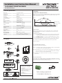
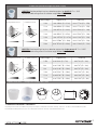
Hytronik HIR27 is a flush-mount PIR motion sensor with one DALI channel output, ideal for automating lighting in various commercial and industrial settings. It features daylight harvesting, manual override, semi-auto mode, and synchronization functions. The sensor has a wide detection range, up to 40 meters in diameter, and can be adjusted to different heights and detection angles. It also allows users to set hold time, stand-by time, and stand-by dimming level, providing precise control over lighting conditions.
Hytronik HIR27 is a flush-mount PIR motion sensor with one DALI channel output, ideal for automating lighting in various commercial and industrial settings. It features daylight harvesting, manual override, semi-auto mode, and synchronization functions. The sensor has a wide detection range, up to 40 meters in diameter, and can be adjusted to different heights and detection angles. It also allows users to set hold time, stand-by time, and stand-by dimming level, providing precise control over lighting conditions.


-
 1
1
-
 2
2
-
 3
3
-
 4
4
-
 5
5
-
 6
6


Hytronik HIR27 is a flush-mount PIR motion sensor with one DALI channel output, ideal for automating lighting in various commercial and industrial settings. It features daylight harvesting, manual override, semi-auto mode, and synchronization functions. The sensor has a wide detection range, up to 40 meters in diameter, and can be adjusted to different heights and detection angles. It also allows users to set hold time, stand-by time, and stand-by dimming level, providing precise control over lighting conditions.
Ask a question and I''ll find the answer in the document
Finding information in a document is now easier with AI
Related papers
-
Hytronik HIR32 PIR DALI Motion Sensor User manual
-
-
-
Hytronik HBHC25 User manual
-
Hytronik HBIR31 Owner's manual
-
-
Hytronik HBIR29-2CH User manual
-
Hytronik HMW24 User manual
-
Hytronik HC049S Operating instructions
-
Hytronik HIM32 User manual
Other documents
-
 DANLERS CN-COPD17M User guide
-
E-Sense Customised Stand-alone User manual
-
SKYDANCE SS-C User manual
-
SKYDANCE SS-B User manual
-
Robus HRC-11 User manual
-
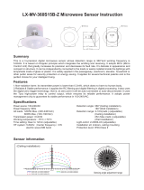 Lexing LX-MV-360S15B-Z Operating instructions
-
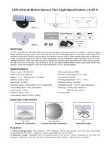 Lexing LX-2P-A Operating instructions
-
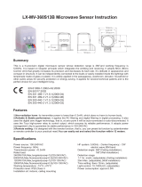 Lexing LX-MV-360S13B Operating instructions
-
-
 Lexing LX-2P-B Operating instructions


