
KM46 PRESSURE
TRANSMITTER INSTALLATION
INSTRUCTIONS
Deutschland / Germany
Max-Planck-Str. 1
D-52499 Baesweiler
Tel.: +49 (0) 2401 808-0
For more information on support and
local partners please visit our web
page at ashcroft.eu or follow the
QR-Code
Ashcroft Instruments GmbH
[email protected] ashcroft.eu
©2018 Ashcroft Instruments GmbH IM-KM46-EN Rev. A 11/18
P/N 095I112-01EN
All specifications are subject to change without notice. All sales subject to standard terms and conditions.
Page 1
Mounting
The KM46 transmitter requires no special
mounting hardware and can be mounted
in any orientation with negligible position
error. Although the units can withstand
considerable vibration without damage or
significant output effects, it is always good
practice to mount the transducer where
there is minimum vibration. For units with
NPT type pressure fittings apply sealing
tape or an equivalent sealant to the
threads before installing. When installing or
removing the unit apply a wrench to the hex
wrench flats, located above the pressure
fitting.
DO NOT tighten by using a pipe wrench on
the housing. A 22 mm (
7
⁄ 8’’) wrench can be
used on the wrench flats of the hex (as per
DIN 894 or similar) with a tightening torque
of ~25 Nm (20 ft lbs). For KM46 models
with detachable electrical connectors a
6 point deep socket can also be used to
install the unit.
Electro-Magnetic Interference
The circuitry of the KM46 transmitter
is designed to minimize the effect of
electromagnetic and radio frequency
interference. To minimize susceptibility
to noise, avoid running the termination
wiring in a conduit which contains high
current AC power cables. Where possible
avoid running the termination wiring near
inductive equipment.
Field Adjustments
The KM46 transmitter is precisely
calibrated and temperature compensated
at the factory to ensure long and stable
performance. There are no field accessible
adjustments on the KM46 transmitter.
ELECTRICAL INSTALLATION
Please refer to the reverse of this page
for power supply requirements and for
appropriate wiring protocol based on
the particular output signal and electrical
termination features of the unit being
installed.
WARNING! READ
BEFORE INSTALLATION
1. GENERAL:
A failure resulting in injury or
damage may be caused by
excessive overpressure, excessive
vibration or pressure pulsation,
excessive instrument temperature,
corrosion of the pressure containing
parts, or other misuse. Consult
Ashcroft Inc., Stratford, Connecticut,
USA before installing if there are any
questions or concerns.
2. OVERPRESSURE:
Pressure spikes in excess of the
rated overpressure capability of the
transducer may cause irreversible
electrical and/or mechanical
damage to the pressure measuring
and containing elements.
Fluid hammer and surges can
destroy any pressure transducer and
must always be avoided. A pressure
snubber should be installed to eliminate
the damaging hammer effects. Fluid
hammer occurs when a liquid flow
is suddenly stopped, as with quick
closing solenoid valves. Surges occur
when flow is suddenly begun, as when
a pump is turned on at full power or a
valve is quickly opened.
Liquid surges are particularly
damaging to pressure transducers if
the pipe is originally empty. To avoid
damaging surges, fluid lines should
remain full (if possible), pumps should
be brought up to power slowly, and
valves opened slowly. To avoid
damage from both fluid hammer and
surges, a surge chamber should be
installed.
Symptoms of fluid hammer and surge’s
damaging effects:
• Pressure transducer exhibits an
output at zero pressure (large zero
offset).
• Pressure transducer output remains
constant regardless of pressure
• In severe cases, there will be no
output.
FREEZING:
Prohibit freezing of media in pressure
port. Unit should be drained (mount
in vertical position with electrical
termination upward) to prevent
possible overpressure damage from
frozen media.
3. STATIC ELECTRICAL CHARGES:
Any electrical device may be
susceptible to damage when exposed
to static electrical charges. To avoid
damage to the transducer observe the
following:
• Ground the body of the transducer
BEFORE making any electrical
connections.
• When disconnecting, remove the
ground LAST!
Note: The shield and drain wire in the
cable (if supplied) is not connected
to the transducer body, and is not a
suitable ground.
DESCRIPTION
The Ashcroft Model KM46 pressure
transducer is a high performance
instrument intended for use in
applications where the process media is
compatible with Titanium sensor material
and process connection.
MECHANICAL INSTALLATION
Environmental
The KM46 transducer can be stored
within a temperature limit of -40°C to
125°C (-40°F to 257°F) and operated
within a temperature limits of -40°C to
105°C (-40°F to 221°F). IP65 or IP67
(ingress protection) rating applies for most
configurations depending on electrical
connection, install accordingly.

KM46 PRESSURE
TRANSMITTER INSTALLATION
INSTRUCTIONS
Deutschland / Germany
Max-Planck-Str. 1
D-52499 Baesweiler
Tel.: +49 (0) 2401 808-0
For more information on support and
local partners please visit our web
page at ashcroft.eu or follow the
QR-Code
Ashcroft Instruments GmbH
[email protected] ashcroft.eu
©2018 Ashcroft Instruments GmbH IM-T5500KF-EN Rev. A 11/18
P/N 095I111-01EN
All specifications are subject to change without notice. All sales subject to standard terms and conditions.
Page 2
POWER
SUPPLY
(+ Power)
(Common)
METER OR
OTHER DEVICE
4-20 mA Output
TRANSDUCER
V+
V-
POWER SUPPLY
(+ Power)
(Common)
TRANSDUCER
V+
V-
METER OR OTHER DEVICE
3-Wire Voltage Output
(+ Output)
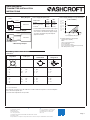
To determine minimum loop supply voltage:
LSV(min)=9(V)+[0,022(A)*R
L
]
Where:
LSV= Loop Supply Voltage (Vdc)
R
L
= R
S
+ R
W
(ohms)
R
L
= Loop Resistance (ohms)
R
S
= Sense Resistance (ohms) [Measuring Instrument]
R
W
= Wiring Resistance (ohms)
10
(min)
40
32 (max)
Loop Supply Voltage (Vdc) [LSV]
Loop Resistance (R
L
-Ohms)
0
02030
200
400
600
800
1000
1200
1400
Power Supply Voltage vs. Loop Resistance
(4-20 mA ONLY)
KM46 ELECTRICAL INSTALLATION
KM46 TERMINATIONS AND WIRING
Wiring Diagrams
Connections
2)
Plug M12x1 Cable port
DIN EN
175301-803-A
DIN EN
175301-803-C
1
2
3
4
1
2
3
2
3
1
Power Power Power Power
1:
2:
3:
4:
UB+
nc
out
nc
red:
black:
white:
UB+
out
nc
1:
2:
3:
UB+
out
nc
1:
2:
3:
UB+
out
nc
Voltage Voltage Voltage Voltage
1:
2:
3:
4:
UB+
nc
UB-
out
red:
black:
white:
UB+
UB-
out
1:
2:
3:
UB+
UB-
out
1:
2:
3:
UB+
UB-
out
nc = not connected
The electrical connection must be made in accordance with the respective connectiondiagram
unless otherwise agreed upon
2)
Custom-made adjustments are possible.
Power Supply Requirements:
Output Signal
Min.
Supply
Max.
Supply
0-10 V 12 Vdc 32 Vdc
0-5 V, 1-5 V, 1-6 V 8 Vdc 32 Vdc
4-20 mA
1)
10 Vdc 32 Vdc
1)
For transmitters with 4-20 mA output signal,
the minimum voltage at the terminals is 10
Vdc. However, the minimum supply voltage
should be calculated using the adjacent
graph and formula.
-
 1
1
-
 2
2


Ask a question and I''ll find the answer in the document
Finding information in a document is now easier with AI
Related papers
-
Ashcroft km46 Installation guide
-
-
-
Ashcroft E2 User manual
-
-
Ashcroft S5500 Installation And Maintenance Instruction Manual
-
-
Ashcroft GL42 Installation guide
-
-
Other documents
-
Omega PX5200 Series Owner's manual
-
-
-
Murphy PXMS Pressure Transmitters and Pressure Transducers Installation guide
-
-
-
-
Honeywell W7750A User manual
-
 Setra Systems 3200 Operating instructions
-
