Page is loading ...

BRIM-T6
USER’S GUIDE


i
NOTICE
Cabletron Systems reserves the right to make changes in specifications and other
information contained in this document without prior notice. The reader should in all cases
consult Cabletron Systems to determine whether any such changes have been made.
The hardware, firmware, or software described in this manual is subject to change without
notice.
IN NO EVENT SHALL CABLETRON SYSTEMS BE LIABLE FOR ANY
INCIDENTAL, INDIRECT, SPECIAL, OR CONSEQUENTIAL DAMAGES
WHATSOEVER (INCLUDING BUT NOT LIMITED TO LOST PROFITS) ARISING
OUT OF OR RELATED TO THIS MANUAL OR THE INFORMATION CONTAINED
IN IT, EVEN IF CABLETRON SYSTEMS HAS BEEN ADVISED OF, KNOWN, OR
SHOULD HAVE KNOWN, THE POSSIBILITY OF SUCH DAMAGES.
© Copyright 1995 by: Cabletron Systems, Inc.
P.O. Box 5005, Rochester, NH 03866-5005
All Rights Reserved
Printed in the United States of America
Order Number: 9031288 September 1995
LANVIEW
,
Remote
LANVIEW
,
SPECTRUM
,
BRIM
,
TPIM-T1
,
TPIM-T2
,
TPIM-T4
,
TPIM-F2
,
TPIM-F3
, and
MicroMMAC
are trademarks of Cabletron
Systems, Inc.
CompuServe
is a registered trademark of CompuServe, Inc.
Intel
is a registered trademark of the Intel Corporation.
Printed on recycled paper.

NOTICE
ii
FCC NOTICE
This device complies with Part 15 of the FCC rules. Operation is subject to the following
two conditions: (1) this device may not cause harmful interference, and (2) this device must
accept any interference received, including interference that may cause undesired
operation.
NOTE:
This equipment has been tested and found to comply with the limits for a Class A
digital device, pursuant to Part 15 of the FCC rules. These limits are designed to provide
reasonable protection against harmful interference when the equipment is operated in a
commercial environment. This equipment uses, generates, and can radiate radio frequency
energy and if not installed in accordance with the operator’s manual, may cause harmful
interference to radio communications. Operation of this equipment in a residential area is
likely to cause interference in which case the user will be required to correct the
interference at his own expense.
WARNING:
Changes or modifications made to this device which are not expressly
approved by the party responsible for compliance could void the user’s authority to operate
the equipment.
DOC NOTICE
This digital apparatus does not exceed the Class A limits for radio noise emissions from
digital apparatus set out in the Radio Interference Regulations of the Canadian Department
of Communications.
Le présent appareil numérique n’émet pas de bruits radioélectriques dépassant les limites
applicables aux appareils numériques de la class A prescrites dans le Règlement sur le
brouillage radioélectrique édicté par le ministère des Communications du Canada.
VCCI NOTICE
This equipment is in the 1st Class Category (information equipment to be used in
commercial and/or industrial areas) and conforms to the standards set by the Voluntary
Control Council for Interference by Information Technology Equipment (VCCI) aimed at
preventing radio interference in commercial and/or industrial areas.
Consequently, when used in a residential area or in an adjacent area thereto, radio
interference may be caused to radios and TV receivers, etc.
Read the instructions for correct handling.

NOTICE
iii
PROGRAM LICENSE AGREEMENT
IMPORTANT:
Before utilizing this product, carefully read this License Agreement.
This document is an agreement between you, the end user, and Cabletron Systems, Inc.
(“Cabletron”) that sets forth your rights and obligations with respect to the Cabletron
software program (the “Program”) contained in this package. The Program may be
contained in firmware, chips or other media. BY UTILIZING THE ENCLOSED
PRODUCT, YOU ARE AGREEING TO BECOME BOUND BY THE TERMS OF THIS
AGREEMENT, WHICH INCLUDES THE LICENSE AND THE LIMITATION OF
WARRANTY AND DISCLAIMER OF LIABILITY. IF YOU DO NOT AGREE TO THE
TERMS OF THIS AGREEMENT, PROMPTLY RETURN THE UNUSED PRODUCT TO
THE PLACE OF PURCHASE FOR A FULL REFUND.
CABLETRON SOFTWARE PROGRAM LICENSE
1. LICENSE.
You have the right to use only the one (1) copy of the Program provided in
this package subject to the terms and conditions of this License Agreement.
You may not copy, reproduce or transmit any part of the Program except as permitted
by the Copyright Act of the United States or as authorized in writing by Cabletron.
2. OTHER RESTRICTIONS. You may not reverse engineer, decompile, or disassemble
the Program.
3. APPLICABLE LAW. This License Agreement shall be interpreted and governed
under the laws and in the state and federal courts of New Hampshire. You accept the
personal jurisdiction and venue of the New Hampshire courts.

NOTICE
iv
EXCLUSION OF WARRANTY & DISCLAIMER OF
LIABILITY
1. EXCLUSION OF WARRANTY. Except as may be specifically provided by Cabletron
in writing, Cabletron makes no warranty, expressed or implied, concerning the
Program (including Its documentation and media).
CABLETRON DISCLAIMS ALL WARRANTIES, OTHER THAN THOSE
SUPPLIED TO YOU BY CABLETRON IN WRITING, EITHER EXPRESS OR
IMPLIED, INCLUDING BUT NOT LIMITED TO IMPLIED WARRANTIES OF
MERCHANTABLITY AND FITNESS FOR A PARTICULAR PURPOSE, WITH
RESPECT TO THE PROGRAM, THE ACCOMPANYING WRITTEN
MATERIALS, AND ANY ACCOMPANYING HARDWARE.
2. NO LIABILITY FOR CONSEQ
UENTIAL DAMAGES. IN NO EVENT SHALL
CABLETRON OR ITS SUPPLIERS BE LIABLE FOR ANY DAMAGES
WHATSOEVER (INCLUDING, WITHOUT LIMITATION, DAMAGES FOR LOSS
OF BUSINESS, PROFITS, BUSINESS INTERRUPTION, LOSS OF BUSINESS
INFORMATION, SPECIAL, INCIDENTAL, CONSEQUENTIAL, OR RELIANCE
DAMAGES, OR OTHER LOSS) ARISING OUT OF THE USE OR INABILITY TO
USE THIS CABLETRON PRODUCT, EVEN IF CABLETRON HAS BEEN
ADVISED OF THE POSSIBILITY OF SUCH DAMAGES. BECAUSE SOME
STATES DO NOT ALLOW THE EXCLUSION OR LIMITATION OF LIABILITY
FOR CONSEQUENTIAL OR INCIDENTAL DAMAGES, OR ON THE
DURATION OR LIMITATION OF IMPLIED WARRANTEES IN SOME
INSTANCES THE ABOVE LIMITATIONS AND EXCLUSIONS MAY NOT APPLY
TO YOU.
UNITED STATES GOVERNMENT RESTRICTED
RIGHTS
The enclosed product (a) was developed solely at private expense; (b) contains “restricted
computer software” submitted with restricted rights in accordance with Section 52227-19
(a) through (d) of the Commercial Computer Software - Restricted Rights Clause and its
successors, and (c) in all respects is proprietary data belonging to Cabletron and/or its
suppliers.
For Department of Defense units, the product is licensed with “Restricted Rights” as
defined in the DoD Supplement to the Federal Acquisition Regulations, Section
52.227-7013 (c) (1) (ii) and its successors, and use, duplication, disclosure by the
Government is subject to restrictions as set forth in subparagraph (c) (1) (ii) of the Rights
in Technical Data and Computer Software clause at 252.227-7013. Cabletron Systems,
Inc., 35 Industrial Way, Rochester, New Hampshire 03867

v
CONTENTS
CHAPTER 1 INTRODUCTION
1.1 USING THIS MANUAL. . . . . . . . . . . . . . . . . . . . . . . . . . . .1-1
1.2 INTRODUCING THE BRIM-T6 . . . . . . . . . . . . . . . . . . . . .1-2
1.3 BRIM SPECIFICATIONS . . . . . . . . . . . . . . . . . . . . . . . . . .1-4
1.4 RELATED DOCUMENTATION. . . . . . . . . . . . . . . . . . . . . .1-4
1.5 GETTING HELP. . . . . . . . . . . . . . . . . . . . . . . . . . . . . . . . .1-5
CHAPTER 2 INSTALLATION
2.1 UNPACKING THE BRIM-T6. . . . . . . . . . . . . . . . . . . . . . . .2-1
2.2 INSTALLING THE BRIM-T6. . . . . . . . . . . . . . . . . . . . . . . .2-1
2.2.1 Installing the BRIM-T6 into a MIM . . . . . . . . . . . . .2-2
2.2.2 Installing the BRIM-T6 into a Standalone Device. .2-4
2.3 CONFIGURING THE BRIM-T6 RING SPEED. . . . . . . . . .2-4
2.4 CONFIGURING AND INSTALLING TPIMs . . . . . . . . . . . .2-6
2.4.1 Configuring TPIMs . . . . . . . . . . . . . . . . . . . . . . . . .2-6
2.4.2 Installing TPIMs . . . . . . . . . . . . . . . . . . . . . . . . . . .2-8
CHAPTER 3 CONNECTING TO THE NETWORK
3.1 CONNECTING STP SEGMENTS . . . . . . . . . . . . . . . . . . .3-1
3.2 CONNECTING UTP SEGMENTS . . . . . . . . . . . . . . . . . . .3-2
3.3 CONNECTING FIBER OPTIC SEGMENTS . . . . . . . . . . .3-2
CHAPTER 4 MONITORING AND TROUBLESHOOTING
4.1 LANVIEW LEDS . . . . . . . . . . . . . . . . . . . . . . . . . . . . . . . .4-1
4.1.1 Describing BRIM-T6 LEDs. . . . . . . . . . . . . . . . . . .4-1
4.2 CHECKING THE CONNECTION. . . . . . . . . . . . . . . . . . . .4-3
APPENDIX A TPIM SPECIFICATIONS
A.1 TWISTED PAIR TPIM PINOUTS: STATION MODE. . . . . .A-1
A.2 FIBER OPTIC TPIM SPECIFICATIONS . . . . . . . . . . . . . .A-1


1-1
CHAPTER 1
INTRODUCTION
Welcome to the
BRIM-T6 USER’S GUIDE
. This manual describes
BRIM-T6 features, installation instructions, and operating procedures. It is
intended for all users of the BRIM-T6.
1.1 USING THIS MANUAL
If you are unfamiliar with Cabletron Systems’ networking products, please
read this manual completely to gain an understanding of the features and
capabilities of the BRIM-T6. Also, you should have a general knowledge
of Token Ring (IEEE 802.5) data communications networks and their
physical layer components before operating the BRIM-T6.
This manual is organized as follows:
Chapter 1,
Introduction
, outlines the contents of this manual and
discusses BRIM-T6 features, capabilities, and specifications. It also
describes how to get technical help and lists related documentation.
Chapter 2,
Installation
, describes how to configure and install the
BRIM-T6 and Token Ring Port Interface Modules (TPIMs).
Chapter 3,
Connecting to the Network
, describes how to establish the
physical link to a Local Area Network (LAN) by connecting standard
network cable segments to the BRIM-T6.
Chapter 4,
Monitoring and Troubleshooting
, describes how to use
the
LANVIEW LEDs diagnostic system to monitor the BRIM-T6’s
operational status. It also describes procedures for resolving problems
encountered establishing a link to a network via the BRIM-T6 interface.
Appendix A,
TPIM Specifications
, describes specifications for Cabletron
Systems’ series of attachable TPIMs.
Appendix B,
Media Specifications
, describes specifications for network
media.

INTRODUCTION
1-2
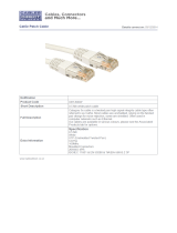
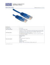
1.2 INTRODUCING THE BRIM-T6
The BRIM-T6 (see Figure 1-1) is a SNMP-manageable daughterboard that
provides a bridging and routing interface for a variety of Cabletron
Systems’ Intel i960-based intelligent Token Ring and Ethernet host
devices (for example, the MicroMMAC-T concentrator and the EMM-E6
management module).
Figure 1-1. BRIM-T6
NOTE
: Contact your Cabletron Representative for up-to-date information
about products that support the BRIM-T6.
Media Flexibility
Used in conjunction with Cabletron Systems’ series of hot swappable
TPIMs, the BRIM-T6 can be configured for connection to all standard
network media. See Section 2.4 for instructions on how to configure and
install TPIMs. Table 1-1 lists TPIMs and their corresponding media and
connector types.
Table 1-1. TPIMs and Corresponding Media
TPIM Corresponding Media Connector
TPIM-T1
Shielded Twisted Pair DB9
TPIM-T2
Unshielded Twisted Pair RJ45
TPIM-T4
Shielded Twisted Pair RJ45
TPIM-F2
Multimode Fiber Optic ST
TPIM-F3
Single-mode Fiber Optic ST
BRIM T6
16Mb XMT
STB RCV

INTRODUCTION
1-3
Jumper Selectable Ring Speed
The BRIM-T6 has a ring speed selection jumper on its component board
that you can use to select operating ring speeds of either 4 or 16 megabits
per second (4 or 16 Mbps). See Section 2.3 for instructions on setting the
ring speed for the BRIM-T6.
Bridge/Routing Protocols
The BRIM-T6 provides Source Routing Transparent (SRT) bridging
between any of the channels or ports in its host MIM or hub and the Token
Ring. BRIM-T6 routing is determined by the routing protocols supported
by the firmware of the host device.
Spanning Tree Algorithm (STA) Compliance
The BRIM-T6 operates in compliance with the functional specifications of
the 802.1d STA, which is included in the firmware of the host device in
which the BRIM-T6 is installed. The STA is used to manage primary and
backup bridges and to maintain the reliability of the multi-bridged
internetwork by detecting and preventing potential data loops.
BRIM-T6 Management
The host device in which the BRIM-T6 is installed provides Local
Management (LM) applications for administering BRIM-T6
bridge/routing functions. The operation of the BRIM-T6 can also be
managed by remote SNMP applications such as Remote LANVIEW and
SPECTRUM. See the documentation included with the host device or
remote management application for information on how to administer
bridge/routing functions.
LANVIEW LEDs
The LANVIEW LEDs on the front panel of the BRIM-T6, together with
the LED on an installed TPIM, provide an at-a-glance means of monitoring
the operational status of the BRIM-T6. LEDs indicate, for example,
network connection status, data transmission activity, and ring speed
operation. See Chapter 4 for more information about LEDs.

INTRODUCTION
1-4
1.3 BRIM SPECIFICATIONS
Environment
Storage temperature: - 30
°
to 90
°
C
Operating temperature: 5
°
to 40
°
C
Operating humidity: 5% to 95% non-condensing
Safety
This unit meets the safety requirements of UL 1950 (without D3
deviations), CSA C22.2 No. 950, and EN60950.
EMI
This unit meets the EMI requirements of FCC Part 15 Class A, EN55022
Class A and VCCI Class I.
EMC
This unit meets the EMC requirements of EN 50082-1 including: IEC
801-2 (ESD) levels 1 through 4, IEC 801-3 (Radiated Susceptibility)
levels 1 through 4, and IEC 801-4 (EFT/B) levels 1 through 4.
NOTE
: It is the network system vendor’s responsibility to ensure that the
total network system, including the BRIM-T6, meets allowed limits of
conducted and radiated emissions.
1.4 RELATED DOCUMENTATION
The following documents provide supplementary information related to
the procedures and technical data in this manual.
Cabletron Documentation
Cabletron Systems’
EMM-E6 User’s Guide
Cabletron Systems’
MicroMMAC-E/MicroMMAC-T User’s Guides
Cabletron Systems’
ESXMIM User’s Guide
Cabletron Systems’
Router Services Manuals
Cabletron Systems’
Guide to Local Area Networking

INTRODUCTION
1-5
Networking Publications
The Simple Book, An Introduction to Management of TCP/IP-based
Internets,
Marshall T. Rose, Prentice-Hall, Inc., 1991
Local Area Networks, Token Ring Access Method
, IEEE Standard 802.5
(1989)
1.5 GETTING HELP
If you need help using the BRIM-T6 or have any questions, comments, or
suggestions concerning this manual, please contact Cabletron Systems
Technical Support Department:
By telephone: (603) 332-9400
Monday-Friday; 8am - 8pm EST
By CompuServe
®
: GO CTRON from any
!
prompt
By Internet mail: [email protected]
By Fax: (603) 337-7055
By BBS: (603) 337-3750
By mail: Cabletron Systems, Inc.
P.O. Box 5005
Rochester, NH 03866-5005

INTRODUCTION
1-6

2-1
CHAPTER 2
INSTALLATION
This chapter describes how to unpack, configure, and install the BRIM-T6.
Because the operation of a BRIM-T6 requires a properly attached and
configured Token Ring Port Interface Module (TPIM), this chapter also
includes TPIM configuration and installation instructions.
CAUTION:
Observe all precautions against electrostatic discharge when
handling the BRIM-T6, TPIMs, and other network devices. Electrostatic
discharge can damage a device’s processing components. Always wear a
properly grounded anti-static wrist strap when handling network devices.
Cabletron Systems includes an anti-static wrist strap and instructions with
all hardware devices.
2.1 UNPACKING THE BRIM-T6
1. Carefully remove the BRIM-T6 from the shipping box and leave it in
its non-conductive bag until ready for inspection and installation.
2. Attach the wrist strap provided with the BRIM-T6 to your wrist and to
a proper ground.
3. Inspect the BRIM-T6 after removing it from the bag. If there is any
damage, notify Cabletron Systems Technical Support Department (see
Section 1.5).
2.2 INSTALLING THE BRIM-T6
This section describes how to install the BRIM-T6 into MIMs and
standalone devices. You should have the following items:
• Anti-static wrist strap
• Two coverplate screws and two standoff, or support post, screws
included with the host device
• #2 Phillips screwdriver

INSTALLATION
2-2
2.2.1 Installing the BRIM-T6 into a MIM
To install the BRIM-T6 into a Media Interface Module (MIM), refer to
Figure 2-1 and Figure 2-2 and follow these steps:
1. Disconnect all cables from the MIM as necessary. Note all prior
cable-to-port connections to ensure proper reconnection.
2. Remove the MIM from the MMAC and place it on its side with its
board components facing up.
3. Remove the BRIM receptacle coverplate from the MIM and the screws
from the standoffs as shown in Figure 2-1.
Figure 2-1. Removing the Coverplate and the Standoff Screws
4. Place the BRIM behind the BRIM receptacle panel on the MIM,
aligning the screw holes on the BRIM with their corresponding screw
holes on the BRIM receptacle panel and on the standoffs as shown in
Figure 2-2.
Standoff
Coverplate

INSTALLATION
2-3
Figure 2-2. Installing the BRIM-T6
5. Insert the connector pins on the underside of the BRIM into the
motherboard connector on the MIM by pressing down firmly on the
rear section of the BRIM until the pins slide all the way into the
connector holes.
6. Fasten the BRIM securely to the MIM motherboard with the
coverplate and standoff screws.
See Section 2.4 for TPIM configuration and installation instructions.
BRIM T6
16Mb XMT
STB RCV
Standoff screw
Coverplate
screw
Connector
Connector pins
under BRIM

INSTALLATION
2-4
2.2.2 Installing the BRIM-T6 into a Standalone Device
Standalone devices have the same physical setup for BRIM installation as
MIMs. So you can refer to Figure 2-1 and Figure 2-2 when installing a
BRIM-T6 into a standalone device.
To install a BRIM into a standalone device:
1. Power off the device and remove its chassis cover. Refer to the
documentation included with the host device for instructions on
removing the chassis cover.
2. Remove the BRIM receptacle coverplate and the standoff screws from
the standoffs as shown in Figure 2-1.
3. Place the BRIM behind the receptacle panel, aligning the screw holes
on the BRIM with their corresponding screw holes on the BRIM
receptacle panel and on the standoffs as shown in Figure 2-2.
4. Insert the connector pins on the underside of the BRIM into the
motherboard connector in the device. Press down firmly on the rear
section of the BRIM until the pins slide all the way into the connector
holes.
5. Fasten the BRIM securely to the device motherboard with the
coverplate and standoff screws.
6. Reinstall the device chassis cover and then power on the device.
2.3 CONFIGURING THE BRIM-T6 RING SPEED
You must configure the BRIM-T6 ring speed to match the ring speed of the
Token Ring to which it is physically linked. The BRIM-T6 ring speed
setting does not, however, have to match the ring speed setting of its host
device.
Also, you must reset the host device containing the BRIM-T6 after you
change the BRIM-T6’s ring speed for the change to take effect.

INSTALLATION
2-5
The BRIM-T6 default ring speed setting is 16 Mbps. The other available
setting is 4 Mbps. To configure the ring speed, refer to the settings
illustrated in Figure 2-3 and follow these steps:
1. Remove the MIM from the MMAC; if the BRIM-T6 is installed in a
standalone device, remove the chassis cover from the device to provide
access to the BRIM-T6’s component board surface.
2. Slide the jumper down over pins 2 and 3 to select a 16 Mbps setting or
over pins 1 and 2 to select a 4 Mbps setting.
3. Reset the device containing the BRIM-T6.
Figure 2-3. BRIM-T6 Ring Speed Settings
J3
16M
SPD
4 M
16M
SPD
4 M
J3
1 2 3
16M
SPD
4 M
J3
1 2 3
Front Panel
Ring Speed Jumper Settings
4 Mbps Setting 16 Mbps Setting

INSTALLATION
2-6
2.4 CONFIGURING AND INSTALLING TPIMs
This section describes how to configure TPIMs and install them into the
BRIM-T6.
2.4.1 Configuring TPIMs
Cabletron TPIMs are shipped pre-configured to support Ring In/Ring Out
(RI/RO) communications. For use in the BRIM-T6 as a bridge/routing
interface, however, they must be reconfigured to support Station port
applications. Additionally, the TPIM-F2 and TPIM-F3 must be configured
to support 802.5J lobe operations via fiber optic cable.
NOTE: TPIM-F2 hardware version 04 and TPIM-F3 hardware version 02
or higher must be used to provide bridge links via fiber optic cable. Prior
versions do not support this functionality with the BRIM-T6.
Refer to the TPIM-F2/TPIM-F3 part number location shown in Figure 2-4
to determine functional compatibility with the BRIM-T6.
To configure TPIMs for use with the BRIM-T6, refer to Figure 2-4 and
follow these steps:
1. Move the RI/RO and Station switch on the TPIMs to the Station (S or
STN) position using a blunt, narrow-tipped instrument such as a
screwdriver or similar instrument.
2. Move the Fiber Key to the 802.5 setting for the TPIM-F2 and TPIM-F3
using the same instrument.
Leave the Phantom Switch setting in the default position for the
TPIM-T1, TPIM-T2, and TPIM-T4.
/