Acrosser Technology AR-B1047 User manual

Category
HDD/SSD enclosures
Type
User manual

Acrosser Technology AR-B1047 is a versatile PC/104 expansion card that offers a range of features to enhance the capabilities of your computer system. With its 40-pin PC/104 connector, it provides connectivity to various peripherals and devices, expanding the functionality of your PC. It also comes with a 64-pin PC/104 connector, allowing for additional expansion options. The AR-B1047 supports both non-chargeable and rechargeable batteries, ensuring uninterrupted operation of your system.

Acrosser Technology AR-B1047 is a versatile PC/104 expansion card that offers a range of features to enhance the capabilities of your computer system. With its 40-pin PC/104 connector, it provides connectivity to various peripherals and devices, expanding the functionality of your PC. It also comes with a 64-pin PC/104 connector, allowing for additional expansion options. The AR-B1047 supports both non-chargeable and rechargeable batteries, ensuring uninterrupted operation of your system.

Page 1 of 4 AR-B1047 Manual
AR-B1047 Manual
Version 1.5
1. SETTING UP THE SYSTEM
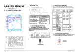
Figure 1-1 Connector & Jumper Location
1.1. PC/104 CONNECTOR
(1) 64 Pin PC/104 Connector Bus A
& B (CN1)
1
2
64-Pin PC/104 Connector
63
64
N.C. ---
SD7 ---
SD6 ---
SD5 ---
SD4 ---
SD3 ---
SD2 ---
SD1 ---
SD0 ---
N.C.---
AEN ---
SA19 ---
SA18 ---
SA17 ---
SA16 ---
SA15 ---
SA14 ---
SA13 ---
SA12 ---
SA11 ---
SA10 ---
A1
A2
A3
A4
A5
A6
A7
A8
A9
A10
A11
A12
A13
A14
A15
A16
A17
A18
A19
A20
A21
A22
A23
A24
A25
A26
A27
A28
A29
A30
A31
A32
--- GND
--- RSTDRV
--- +5 VDC
--- N.C.
--- N.C.
--- N.C.
--- N.C.
--- N.C.
--- +12 VDC
--- N.C.
--- -SMEMW
--- -SMEMR
--- -IOW
--- -IOR
--- N.C.
--- N.C.
--- N.C.
--- N.C.
--- N.C.
--- N.C.
--- N.C.
SA9 ---
SA8 ---
SA7 ---
SA6 ---
SA5 ---
SA4 ---
SA3 ---
SA2 ---
SA1 ---
SA0 ---
GND ---
B1
B2
B3
B4
B5
B6
B7
B8
B9
B10
B11
B12
B13
B14
B15
B16
B17
B18
B19
B20
B21
B22
B23
B24
B25
B26
B27
B28
B29
B30
B31
B32
--- N.C.
--- N.C.
--- N.C.
--- N.C.
--- N.C.
--- N.C.
--- N.C.
--- +5 VDC
--- N.C.
--- GND
--- GND
CN1
12
Figure 1-2 CN1: 64-Pin PC/104
Connector Bus A & B
(2) 40 Pin PC/104 Connector Bus C
& D (CN2)
1
2
39
40
40 Pin PC/104 Connector
GND ---
N.C. ---
N.C. ---
N.C. ---
N.C. ---
N.C. ---
N.C. ---
N.C. ---
N.C. ---
N.C. ---
N.C. ---
N.C. ---
N.C. ---
N.C. ---
N.C. ---
N.C. ---
N.C. ---
N.C. ---
N.C. ---
N.C. ---
C1
C2
C3
C4
C5
C6
C7
C8
C9
C10
C11
C12
C13
C14
C15
C16
C17
C18
C19
C20
--- GND
--- N.C.
--- N.C.
--- N.C.
--- N.C.
--- N.C.
--- N.C.
--- N.C.
--- N.C.
--- N.C.
--- N.C.
--- N.C.
--- N.C.
--- N.C.
--- N.C.
--- N.C.
--- +5 VDC
--- N.C.
--- GND
--- GND
D1
D2
D3
D4
D5
D6
D7
D8
D9
D10
D11
D12
D13
D14
D15
D16
D17
D18
D19
D20
1
2
CN2
Figure 1-3 CN2: 40-Pin PC/104
Connector Bus C & D
1.2. BATTERY SETTING
(1) Battery Charge Select (JP1)
Non-chargeable Battery
Factory Preset
Re-chargeable Battery
12 12
345 345
Figure 1-4 JP1-1 & JP1-2: Battery
Charge Select
2
3
ABC CBAABC
1
1
2
1
2
1
2
JP1
SW1
U4
3
M3
2
M2
1
M1
DOC
MEM5
MEM4
MEM3
MEM2
MEM1
J1
CN2
CN1
BAT1
H4
H3
H2H1
Page 2 of 4 AR-B1047 Manual
(2) External Battery Header (J1)
1 Battery+
2 Battery-
Figure 1-5 J1: External Battery Connector
1.3. DIP SWITCH SETTING (SW1)
There is 1-DIP Switch located on the AR-B1047. If you want to use the 12V FLASH,
please use the external 12V voltage, the AR-B1047 does not support the 12V voltage.
It performs the following functions:
ON
123456
OFF
7 8
SW1
Figure 1-6 SW1: Switch Select
SW1-1 Sets the base I/O port address
SW1-2 & SW1-7 Sets the starting memory address
SW1-3 & SW1-4 Sets the drive number of solid state disk
SW1-5 & SW1-6 Sets the used ROM memory chips
SW1-8 Set the DiskOnChip
1.3.1. I/O Port Address Select (SW1-1)
Switch 1 (SW1-1) Base Port Solid State Disk
OFF 224h 224h-227h
ON 2A4h 2A4h-2A7h
Table 1-1 I/O Port Address Select
1.3.2. SSD & DiskOnChip Firmware Address Select (SW1-2,
SW1-7 & SW1-8)
Switch 2
(SW1-2)
Switch 7
(SW1-7)
Switch 8
(SW1-8)
BIOS
Memory
Address
Bank
Memory
Address
D.O.C.
Memory
Address
OFF OFF OFF CC00h CE00h D000h
ON OFF OFF D000h D200h D400h
OFF OFF ON CC00h CE00h --
ON OFF ON D000h D200h --
OFF ON OFF -- CE00h CC00h
ON ON OFF -- D200h D000h
OFF ON ON -- -- --
ON ON ON -- -- --
Table 1-2 SSD Firmware Address Select
If you are going to install the EMM386.EXE driver, please use the [X] option to
prevent EMM386.EXE from using the particular range of segment address as an EMS
page, which is used by AR-B1047. For example, write a statement in the
CONFIG.SYS file as follow: (If the memory configuration of AR-B1047 is CC00:0)
DEVICE=C:\DOS\EMM386.EXE X=CC00-CFFF
1.3.3. SSD Drive Number (SW1-3 & SW1-4)
The SSD BIOS will simulate one disk drive when only (FLASH) EPROM or SRAM
(starting from MEM1 socket) is installed. The drive numbers with respect to the
switch setting when the AR-B1047 simulates single disk drives.
SW1-3 SW1-4 Occupies floppy disk number (SSD)
OFF OFF 0 or 1 (Note 1)
ON OFF 0 or 2 (Note 2)
OFF ON 0
ON ON 0
Table 1-3 SSD Drive Number
Page 3 of 4 AR-B1047 Manual
NOTE: 1. If there is no DOS on this SSD, the disk number will be 1 (B:). If any DOS is
found by the AR-B1047 SSD BIOS, the disk number will be 0 (A:) But, you
can change the disk number from 0 to 1 by pressing the <ESC> key during
system bootup.
2. If there is no DOS on this SSD, the disk number will be 2 (C: or D: or…). If
any DOS is found by the AR-B1047 SSD BIOS, the disk number will be 0
(A:). But, you can change the disk number from 0 to 2 by pressing the
<ESC> key during system bootup.
(1) Simulate 2 Disk Drive
When (FLASH) EPROM and SRAM are both used on the AR-B1047, or you only have
installed SRAM that does not start from MEM1 socket, the AR-B1047 will simulate two
disk drives.
Occupies floppy disk number
SW1-3 SW1-4
FLASH (EPROM) SRAM
OFF OFF 0 or 1 (Note 1) 2
ON OFF 0 or 2 (Note 2) 3
OFF ON 0 1
ON ON 0 2
Table 1-4 SSD Drive Number for Simulate 2 Disk Drives
NOTE: 1. If there is no DOS on this SSD, the disk number will be 1 (B:). If any DOS
is found by the AR-B1047 SSD BIOS, the disk letter will be 0 (A:). But, you
can change the disk number from 0 to 1 by pressing the <ESC> key during
system bootup.
2. If there is no DOS on this SSD, the disk number will be 2 (C: or D: or….). If
any DOS is found by the AR-B1047 SSD BIOS, the disk number will be 0
(A:). But, you can change the disk number from 0 to 2 by pressing the
<ESC> key during system bootup.
(2) Disk Drive Name Arrangement
Floppy disk No. Logical hard disk
Condition
0 1 2 3 1 2 3 4
No Logical hard disk A: B: C: D: -- -- -- --
1 Logical hard disk A: B: C: D: E: -- -- --
2 Logical hard disk A: B: C: D: E: F: -- --
3 Logical hard disk A: B: C: D: E: F: G: --
4 Logical hard disk A: B: C: D: E: F: G: H:
Table 1-5 SSD Drive Number for DOS Version before 5.0
Floppy disk No. Logical hard disk
Condition
0 1 2 3 1 2 3 4
No Logical hard disk A: B: C: D: -- -- -- --
1 Logical hard disk A: B: D: E: C: -- -- --
2 Logical hard disk A: B: E: F: C: D: -- --
3 Logical hard disk A: B: F: G: C: D: E: --
4 Logical hard disk A: B: G: H: C: D: E: F:
Table 1-6 SSD Drive Number for DOS Version 5.0 and Newer
1.3.4. ROM Type Select (SW1-5 & SW1-6)
SW1-5 & SW1-6 are used to select the memory type of ROM disk section.
SW1-5 SW1-6 EPROM Type
OFF OFF UV EPROM (27Cxxx)
ON OFF 5V FLASH 29Fxxx
OFF ON 5V FLASH(29Cxxx & 29EExxx)(*Note)
ON ON 12V FLASH (28Fxxx)
Table 1-7 ROM Type Select
NOTE: It is also supported 28EExxx 5V FLASH, the BIOS message will still show 5V
FLASH (29Cxxx or 29EExxx) disk.
Page 4 of 4 AR-B1047 Manual
1.4. MEMORY TYPE SETTING (M1, M2 & M3)
The M1 jumper block is used to configure the memory type of MEM1 and MEM2, M2
is for MEM3 and MEM4, M3 is for MEM5. Please refer to the following chart to select
the correct memory type.
!
M1:is used to configure the memory type of MEM1 & MEM2
!
M2:is used to configure the memory type of MEM3 & MEM4
!
M3:is used to configure the memory type of MEM5
M1, M2, & M3
EPROM (128KX8, 256KX8 and 512KX8)
5V/12V FLASH (64KX8, 128KX8 and 256KX
8
(Factory Preset)
5V FLASH (512KX8 Only)
SRAM
M1, M2, & M3
M1, M2, & M3
1
2
3
ABC
1
2
3
ABC
1
2
3
ABC
M1, M2, & M3
1
2
3
ABC
123
JP1
1MX8 EPROM (Only)
45
123
JP1
45
123
JP1
45
123
JP1
45
Figure 1-7 M1~M3 & JP1-3~JP1-5: Memory Type Setting
1.5. HOW TO USE THE D.O.C.
This section provides the information about how to use the D.O.C. (DiskOnChip).
Step 1:
Use SW1-8 set the DiskOnChip to Enable or Disable.
Step 2:
Insert programmed DiskOnChip into sockets DOC.
Step 3:
Line up and insert the AR-B1047 card into any free slot of your
computer.
ON
12345678
OFF
Figure 1-8 D.O.C. Switch Setting
CAUTION: When the power is turned off, please note the following precautions.
1. If your data has been stored in the SRAM disk, do not change the
jumper position or data will be lost.
2. Make sure jumpers are set properly. If you mistakenly set the
jumpers for SRAM and you have EPROM or FLASH installed, the
EPROM or FLASH will drain the battery’s power.
3. If you want to use the 12V FLASH, please use the external 12V
voltage, the AR-B1047 does not support the 12V voltage.
Note:
If the content in Setting is inconsistent with the CD-ROM. Please refer to
the Setting as the priority.
  • Page 1 1
  • Page 2 2
  • Page 3 3
  • Page 4 4

Acrosser Technology AR-B1047 User manual

Category
HDD/SSD enclosures
Type
User manual

Acrosser Technology AR-B1047 is a versatile PC/104 expansion card that offers a range of features to enhance the capabilities of your computer system. With its 40-pin PC/104 connector, it provides connectivity to various peripherals and devices, expanding the functionality of your PC. It also comes with a 64-pin PC/104 connector, allowing for additional expansion options. The AR-B1047 supports both non-chargeable and rechargeable batteries, ensuring uninterrupted operation of your system.

Ask a question and I''ll find the answer in the document

Finding information in a document is now easier with AI