Page is loading ...

1
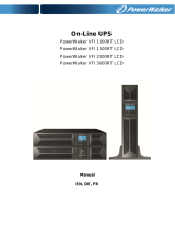
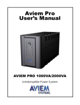
1. INTRODUCTION
This series is a compact and fully pure sinewave line interactive UPS, and it
designs for critical application and environment, such as desktops, servers,
workstations, and other networking equipments. This model is available in the
output ratings of 750, 1000, 1500, 2000, and 3000VA. This series protects
your sensitive electronic equipments against power problems including power
sags, spike, brownouts, line noise, and blackouts.
This series designs from two-in-one form factor; it can be placed either in
Rack 2U or Tower. The front panel of the UPS includes LED indicators and
four push buttons (Power Switch, UPS Test/Silence, Configure, and Enter)
that allow to monitor easily, configuration and control, AC line-in, notification
of site wiring fault and output load status of the UPS. It also includes four
LED bar graphic (Load/Battery Level Indication); two status indications (On
AC, On Battery); five alarm indications (Overload, Over Temperature, Site
Wiring Fault, Battery Fault, Self Test Failure). A push button from the front
panel allows silencing of the AC fail alarm and the initiation of the UPS self
test sequence as well. The UPS case for 750 ~ 2000VA is made of plastic as
well as 3000VA is made of metal.
This series is powered from the AC mains and supply AC outputs via
receptacles on the rear panel. Communication and control to the unit is
available through serial or USB ports located on the rear panel. The serial
port will support communications directly with a server. The communications
protocol for the serial ports shall conform to true RS232 interface.
Features:
Microprocessor control guarantees high reliability
High frequency design
Built-in boost and buck AVR
User replaceable design for 1500VA or above
Selectable output range and line sensitive
Cold startup capability
Built-in Dry contact/RS-232/USB communication port
SNMP allows for web-based remote or monitoring management
Enable to extend runtime with scalable external battery pack for
1500VA or above
Overload, Short-circuit, and overheat protection
Rack/Tower 2 in 1 Design
19” rack mount available for all models

2. SAFETY INSTRUCTION – CAUTION
IMPORTANT SAFETY INSTRUCTIONS
SAVE THESE INSTRUCTIONS - This Manual Contains Important
Instructions that should be Followed during Installation and
Maintenance of the UPS and Batteries.
WARNING: Do not attempt to repair and service this UPS. This UPS
contains high voltages which could cause the risk of electrical shock.
Even this UPS is disconnected from the electrical outlet, the dangerous
voltage still may be present through the battery. All maintenance and
battery replacement should be performed by qualified service
personnel only.
1. This UPS must be placed indoors with adequate airflow and free of
contamination. To install or operate it in a clean and indoor environment,
free from moisture, flammable liquids, and direct sunlight. Ambient
temperature range must be 0°C to 40°C (32°F to 104°F).
2. This UPS is designed for Commercial/Industrial use only. It is not
intended for use with life support application and other designated
“life-critical” devices.
3. Do not remove the input power cord when this UPS is turned on. This
removes the safety ground from this UPS and the equipment connected to
the UPS.
4. Turn off this UPS and disconnect input power cord before battery
replacement.
5. Battery contains high short-circuit current. Replacing or servicing the
battery which should be performed and supervised by qualified service
personnel knowledgeable of batteries and required precautions.
Remove watches and jewelries
Use tools with insulated handles
Wear rubber gloves and boots.
Do not lay tools or metal parts on top of batteries.
Disconnect charging source prior to connecting or disconnecting battery
terminals.
3
2

3
6. When replacing the batteries, use the appropriate replacement battery kits,
same number and type of battery are MUST.
7. Do not open or mutilate the battery. Released electrolyte is harmful to skin
and eyes that may be toxic.
8. Do not dispose of battery in a fire. Battery may explode. Proper disposal of
battery is required. Please refer to your local laws and regulations for
disposal requirements.
9. To reduce the risk of fire, use only No. 26 AWG or larger
telecommunication line cord.

4
2. SAFETY INSTRUCTION – CAUTION
10. This UPS contains high voltages which may cause the risk of electric
shock. Do not remove cover. There are no user replaceable parts inside
this UPS. Please contact your local dealer or distributor for service.
11. To reduce the risk of fire, connect to a circuit provided with 1.25(at least
20A) amperes maximum branch circuit over-current protection in
accordance with the National Electric Code, ANSI/NFPA.
12. This pluggable type A equipment with battery already installed by the
supplier is operator installable and may be operated by laymen.
13. During the installation of this equipment it should be assured that the sum
of the leakage currents of the UPS and the connected loads does not
exceed 3.5mA.
14. Attention, hazardous through electric shock. Also with disconnection of
this unit from the mains, hazardous voltage still may be accessible
through supply from battery. The battery supply should be therefore
disconnected in the plus and minus pole of the battery when maintenance
or service work inside the UPS is necessary.
15. The mains socket outlet that supplies the UPS shall be installed near the
UPS and shall be easily accessible.

2. SAFETY INSTRUCTION – CAUTION
2.1 Description of Commonly Used Symbols
Symbol & Description
Symbol Description
Alert you to pay special attention
Caution of high voltage
Alternating current source(AC)
Direct current source(DC)
Protective ground
Recycle
Keep UPS in a clear area
5

3. SYSTEM DESCRIPTION
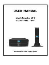
Front Panel —
No. Function Description
1 Switch ON/OFF
2 Switch Self-Test/ Alarm Silence
3 Switch Config
4 Switch Enter
5 LED Input Type(Operating Mode)
6 LED Voltage Range
7 LED Bad Battery
8 LED Overload
9 LED Fault
10 LED PCB Fail (or Site Fault)
11 LED Battery Mode
12 LED Line Mode
13 LED Capacity of Load
14 LED Capacity of Battery
6

3. SYSTEM DESCRIPTION
1. Power Switch:
- To turn on the UPS, press the button more than three seconds
- To turn off the UPS, press and hold this button until you hear the UPS
beep ceases.
2. UPS Test/ Alarm Silence:
- The battery is fully charged during in line mode. To perform self-test
function, press and hold the
button for five seconds.
- To disable alarm buzzer, press this button for a second that will turn off
the alarm buzzer. Each time a new alarm event is encountered the
alarm that will sound and press this button to turn off the alarm.
Note: Unable to disable alarm buzzer as below conditions: Low
Battery, Overload, Fan Failed, Fan Fault Time Out, Over
Temperature.
3. Configure:
To reconfigure the internal UPS setup options, follow the procedure as
below:
Step 1: Press the Configure
button more than three seconds. Then
UPS will transfer from configure mode to “output voltage mode”.
Step2: Press the Configure
button more than one second, the UPS
allows you to select the “output voltage mode” one by one.
Step3: After selecting the mode, press the Enter
button more than
three seconds, the “output voltage mode” is configured.
Step4: UPS will automatically transfer from configure mode to “operating
mode”.
Step5: Press the Configure
button more than one second; the UPS
will allow you to select the “operating mode” one by one.
Step6: After selecting the mode, press the
button more than three
seconds, the “operating mode” is configured.
4. Enter:
Press the
button after you choose the mode.
7

3. SYSTEM DESCRIPTION
5. Input Type (Operating Mode) LED:
Normal mode: The Yellow LED indicator will illuminate during normal
mode, the UPS accepts AC input voltage range from +/-20%.
Generator: No change to voltage window. However, the low frequency
transfer point is changed to 40Hz and there is no limitation for high
frequency transfer point.
Wide range: The LED indicator will illuminate, the UPS accepts AC
input voltage range from -30% ~ +20%.
6. Voltage Range (Output Voltage Mode) LED:
UPS Output voltages selection: 110VAC/120VAC/127VAC or
220VAC/230VAC/240VAC.
7. Bad Battery LED:
The LED indicator will light on when the battery is failed or if the
battery is disconnected, LED will flash every two seconds. Please
check your battery connection; replace the battery or contact your
local dealer for a battery replacement kit.
8. Overload LED:
The LED indicator will light on when the UPS overload timeout.
9. Fault LED:
The LED indicator will light on when the UPS fails/overload is
timeout /or short-output.
8

3. SYSTEM DESCRIPTION
10. PCB FAIL LED(or SITE FAULT LED):
PCB FAIL LED: the LED indicator will light on when the power module
of UPS fails.
SITE FAULT LED: the LED indicator will light on when UPS is plugged
into an improperly utility
Note: “SITE FAULT” function is only available for 120Vac models.
11. BAT Mode LED (Battery Mode):
The LED indicator will flash every five seconds when the UPS is providing
battery power to your equipment. On the other hand, the LED indicator
gives you a warning which will flash every two seconds when the battery is
low.
12. Line Mode LED:
The line LED indicator illuminates when the AC source is present.
13. Capacity of Load LED:
Load Indicator: The
LED indicator and the load level indicator
will illuminate to show the load level.
Load Level Indicator:
There are four LED bar graphic to indicate the percentage of UPS
load capacity which is being used by the protected equipment. The
greater the load, the more LED indicators that will be illuminated.
Each LED indicator designates a 25% of the UPS output capacity.
Please see the following load level respectively.
0 ~ 25%: 1
st
LED indicator
26% ~ 50%: 1
st
and 2
nd
LEDs indicator
51% ~ 75% : 1
st
, 2
nd
, and 3
rd
LEDs indicator
76% ~ 100%: All of four LED indicators will illuminate
14. Capacity of Battery LED:
Battery Indicator: The
LED indicator and battery level indicator
will illuminate to show battery level.
9

3. SYSTEM DESCRIPTION
Battery Level Indicator:
There are four LED bar graphic to indicate the amount of battery
capacity remaining. The higher the battery capacity, the more LED
indicators that will be illuminated. Each LED indicator designates a 25%
capacity level. Please see the following capacity level respectively.
0 ~ 25%: 4
th
LED indicator
26% ~ 50%: 3
rd
and 4
th
LEDs indicator
51% ~ 75% 2
nd
, 3
rd
, and 4
th
LEDs indicator
76% ~ 100%: All of four LED indicators will illuminate
Indicator Condition —
Condition
Alarm
Utility Mode
(AC Mode)
Line LED Lighting
Backup Mode
(Power Failure)
Flashing every four seconds
Site fault LED lighting (For 120VAC Models) Site Fault
4 segment LED bar:
0~25%: 4
th
LED lighting; 26~50%: 3
rd
and 4
th
LEDs lighting; 51~75%: 2
nd
, 3
rd
, and 4
th
LEDs
lighting; 76~100%: all of 4 LEDs lighting
UPS Fault Fault LED lighting
Overload Overload LED lighting
Low Battery Battery LED flashing every second
Audible Alarm Condition —
Condition
Alarm
Backup Mode
(Power Failure)
Sounding every four seconds
Low Battery Sounding every second
UPS Fault Continuously Sounding
Overload Sounding every second
Battery Replacement Sounding every second
10

3. SYSTEM DESCRIPTION
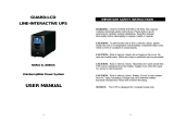
Back Panel -
VI-750R / 1000R
Rear panel description for LV and HV models table
Function
No.
LV model (110/120/127Vac) HV model (220/230/240Vac)
1
Modem/Network Surge Protection
2
RS232 / Dry-Contact Communication Port
3
USB Communication Port
4
AC Input Power cord AC Input & Protection
5
AC Output NEMA AC Output IEC
11

3. SYSTEM DESCRIPTION
VI-1500R / 2000R
1. Host Rear Panel:
The host rear panel pictures for HV and LV models are shown as below:
Host Rear panel for HV model
Host Rear panel for LV model
13
12

Rear panel description for LV and HV models table
Function
No.
LV model (110/120/127Vac) HV model (220/230/240Vac)
1 RS232 / Dry-Contact Communication Port
2 SNMP Port
3 USB Port
4 EPO
5 Modem/Network Surge Protection
6 N/A Input Breaker
7 AC Output
8 AC Input AC Input
9 External Battery Connector
2. EBM Rear Panel:
The EBM rear panel pictures is shown as below:
EBM Rear panel for HV model
EBM Rear panel for HV model
13

3. SYSTEM DESCRIPTION
EBM Rear panel for LV model
Rear panel description for LV and HV models table
13
Function
No.
LV model (110/120/127Vac) HV model (220/230/240Vac)
1 Battery Output Power Cord
2 AC Output
3 External Battery Connector
4 Output Breaker N/A
5 Output Breaker N/A
6 Output Receptacles Output Receptacles
14

3. SYSTEM DESCRIPTION
VI-3000R
Rear panel for HV model
Rear panel for LV model
16
15

Rear panel description for LV and HV models table
Function
No.
LV model (110/120/127Vac) HV model (220/230/240Vac)
1 Output Breaker
2 AC Output
3 AC Input
4
Modem/Network Surge
Protection
Modem/Network Surge
Protection
5 Input Breaker N/A
6 Input Power Cord N/A
7 SNMP Slot SNMP Slot
8 External Battery Connector External Battery Connector
9 EPO EPO
10 USB Port USB Port
11 RS232 / Dry-Contact Communication Port
16

4. INSTALLATION
1. Inspecting the Equipment
Inspect the UPS upon receipt. If the UPS has been damaged during
shipment, keep the box and packing material for the carrier. Notify
the carrier and dealer immediately.
2. Placement
This UPS should be installed indoors with adequate airflow and free of
contamination. Locate it in a clean and indoor environment, free from
moisture, flammable liquids, and direct sunlight. Maintain a minimum
clearance of 4 inches (100mm); an ambient temperature range must be
0°C to 40°C (32°F to 104°F), and operating humidity range must be 20%
to 80% relative humidity (non-condensing).
CAUTION: The long term uses at ambient temperature in higher than 25°C
which should reduce battery life. In addition, place the UPS unit away from
the monitor at least 20cm to avoid interference.
3. Charging
This UPS is shipped from the factory with its internal battery fully charged;
however, some charge may be lost during shipping. The battery should be
recharged prior to use. Plug the UPS into an appropriate power supply
and allow the UPS to charge at least 4 hours.
4. Load Connection
Connect one load-related device to each of the power receptacles supplied
at the rear of the UPS.
5. Modem/Phoneline Connection
Plug incoming telephone line into the “In” socket at the back of the UPS.
Use on telephone line cable and plug one end of the telephone line cable to
the “Out” socket at the back of the UPS. Plug the other end to the modem
input socket.
6. DC Start Function
DC Start Function enables UPS to be started up when AC utility power is
not available and battery is full charged. Just simply press the On/Off switch
to turn on the UPS.
14
17

4. INSTALLATION
7. Turn On/Off
To turn on/off the UPS, you should press the on/off switch three
seconds at least.
8. UPS Setup
All models series are designed for tower and rack purpose. They can
be installed as a 19 inch equipment rack, and 3000VA can be placed
in a tower (with optional stand) as well. Please follow the instruction
for Tower Setup or Rack-Mount Setup.
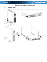
9. Tower Setup
This series can be placed in horizontally and vertically. 3000VA
model is designed in a rack itself. As a tower, it is provided with the
optional UPS stand to stabilize the UPS when the UPS is positioned
in vertically. The UPS stand must be attached to the bottom of the
tower.
VI-750R / 1000R
Tower form
15
18

4. INSTALLATION
VI-1500R / 2000R
Host and EBM integrate into three types of tower forms
16
(a) Tower form 1 (b) Tower form 2
(c) Tower form 3
19

4. INSTALLATION
VI-3000R
Tower form setup
1. Slide down the UPS vertically and put two UPS stands at the
end of the tower.
2. Place the UPS into two stands carefully.
20
/