Page is loading ...

Model 54eA
Amperometric HART
®
Analyzer/Controller
Instruction Manual
51-54eA/rev.J
May 2006

ESSENTIAL INSTRUCTIONS
READ THIS PAGE BEFORE PROCEEDING!
Rosemount Analytical designs, manufactures, and tests its products to
meet many national and international standards. Because these instru-
ments are sophisticated technical products, you must properly install, use,
and maintain them to ensure they continue to operate within their normal
specifications. The following instructions must be adhered to and integrat-
ed into your safety program when installing, using, and maintaining
Rosemount Analytical products. Failure to follow the proper instructions
may cause any one of the following situations to occur: Loss of life; per-
sonal injury; property damage; damage to this instrument; and warranty
invalidation.
• Read all instructions prior to installing, operating, and servicing the prod-
uct. If this Instruction Manual is not the correct manual, telephone 1-
800-654-7768 and the requested manual will be provided. Save this
Instruction Manual for future reference.
• If you do not understand any of the instructions, contact your
Rosemount representative for clarification.
• Follow all warnings, cautions, and instructions marked on and supplied
with the product.
• Inform and educate your personnel in the proper installation, operation,
and maintenance of the product.
• Install your equipment as specified in the Installation Instructions of the
appropriate Instruction Manual and per applicable local and national
codes. Connect all products to the proper electrical and pressure
sources.
• To ensure proper performance, use qualified personnel to install, oper-
ate, update, program, and maintain the product.
• When replacement parts are required, ensure that qualified people use
replacement parts specified by Rosemount. Unauthorized parts and
procedures can affect the product’s performance and place the safe
operation of your process at risk. Look alike substitutions may result in
fire, electrical hazards, or improper operation.
• Ensure that all equipment doors are closed and protective covers are in
place, except when maintenance is being performed by qualified per-
sons, to prevent electrical shock and personal injury.
WARNING
ELECTRICAL SHOCK HAZARD
Making cable connections to and servicing this instru-
ment require access to shock hazard level voltages
which can cause death or serious injury, therefore,
disconnect all hazardous voltage before accessing
the electronics.
Relay contacts made to separate power sources must
be disconnected before servicing.
Electrical installation must be in accordance with the
National Electrical Code (ANSI/NFPA-70) and/or any
other applicable national or local codes.
Unused cable conduit entries must be securely sealed
by non-flammable closures to provide enclosure
integrity in compliance with personal safety and envi-
ronmental protection requirements. Use NEMA 4X or
IP65 conduit plugs supplied with the instrument to
maintain the ingress protection rating (IP65).
For safety and proper performance this instrument
must be connected to a properly grounded three-wire
power source.
Proper relay use and configuration is the responsibili-
ty of the user. No external connection to the instru-
ment of more than 60VDC or 43V peak allowed with
the exception of power and relay terminals. Any viola-
tion will impair the safety protection provided.
Do not operate this instrument without front cover
secured. Refer installation, operation and servicing to
qualified personnel.
WARNING
This product is not intended for use in the resi-
dential, commercial or light industrial environ-
ment per certification to EN61326.
Emerson Process Management
Liquid Division
2400 Barranca Parkway
Irvine, CA 92606 USA
Tel: (949) 757-8500
Fax: (949) 474-7250
http://www.raihome.com
© Rosemount Analytical Inc. 2006
About This Document
This manual contains instructions for installation and operation of the Model 54eA Amperometric
HART Analyzer/Controller. The following list provides notes concerning all revisions of this document.
Rev. Level Date Notes
A 11/01 This is the initial release of the product manual. The manual has been reformatted to reflect the
Emerson documentation style and updated to reflect any changes in the product offering.
B 2/02 Revised wiring diagrams on pages 9, 11, & 13.
C 5/02 Added configuration note to page 10.
D 11/02 Change to intro verbiage in Section 5.3 on page 26.
E 11/02 Added note re 499A sensors to page 8.
F 4/03 Added monochloramine section and updated CE info.
G 8/03 Minor textual revisions on pages 48, 65, 67, 93.
H 12/03 Updated ISO & warranty info, and fixed minor typos throughout.
I 4/05 Added note re ordering replacement boards/integrated board stack on page 105.
J 5/06
Noted 0-20 mA limitation for HART versions on pp. 18, 25, & 31.


MODEL 54eA TABLE OF CONTENTS
MODEL 54eA ANALYZER/CONTROLLER
TABLE OF CONTENTS
Section Title Page
1.0 SPECIFICATIONS................................................................................................... 1
1.1 Features and Applications ....................................................................................... 1
1.2 Specifications........................................................................................................... 2
1.3 Ordering Information................................................................................................ 4
2.0 INSTALLATION....................................................................................................... 5
2.1 Unpacking and Inspection ....................................................................................... 5
2.2 Installation ...............................................................................................................5
3.0 WIRING ................................................................................................................... 8
3.1 General.................................................................................................................... 8
3.2 Power, Alarm, and Output Wiring ............................................................................ 8
3.3 Sensor Wiring.......................................................................................................... 10
4.0 DISPLAY AND OPERATION .................................................................................. 16
4.1 General Description................................................................................................. 16
4.2 Display..................................................................................................................... 16
4.3 Key Functions and Controls .................................................................................... 16
4.4 Alarm Status ............................................................................................................ 16
5.0 SOFTWARE CONFIGURATION ............................................................................. 17
5.1 Changing Alarm Setpoints....................................................................................... 24
5.2 Ranging the Outputs ............................................................................................... 25
5.3 Changing Output Setpoints (PID only) .................................................................... 26
5.4 Testing Outputs and Alarms .................................................................................... 27
5.5 Choosing Display Options ....................................................................................... 28
5.6 Changing Output Parameters.................................................................................. 30
5.7 Changing Alarm Parameters ................................................................................... 33
5.8 Configuring the pH Measurement ........................................................................... 38
5.9 Temperature Compensation and Temperature Units............................................... 41
5.10 Noise Reduction ...................................................................................................... 42
5.11 Main Sensor Calibration Parameters ...................................................................... 43
5.12 Barometric Pressure................................................................................................ 44
5.13 Security.................................................................................................................... 45
5.14 Controller Mode Priority........................................................................................... 46
6.0 CALIBRATION - TEMPERATURE.......................................................................... 47
6.1 Introduction.............................................................................................................. 47
6.2 Temperature Calibration .......................................................................................... 48
7.0 CALIBRATION - DISSOLVED OXYGEN................................................................ 49
7.1 Introduction.............................................................................................................. 49
7.2 Zeroing the Sensor.................................................................................................. 50
7.3 Calibrating the Sensor in Air.................................................................................... 51
7.4 Calibrating the Sensor Against a Standard Instrument ........................................... 53
7.5 Calibrating Barometric Pressure ............................................................................. 54
8.0 CALIBRATION - FREE CHLORINE (499 ACL-01) ................................................ 55
8.1 Introduction.............................................................................................................. 55
8.2 Zeroing the Sensor.................................................................................................. 56
8.3 Full Scale Calibration............................................................................................... 57
8.4 Dual Slope Calibration............................................................................................. 58
i

9.0 CALIBRATION - FREE CHLORINE (498 ACL-01) ................................................ 60
9.1 Introduction.............................................................................................................. 60
9.2 Zeroing the Sensor.................................................................................................. 61
9.3 Full Scale Calibration............................................................................................... 62
9.4 Dual Slope Calibration............................................................................................. 63
10.0 CALIBRATION - TOTAL CHLORINE ..................................................................... 65
11.0 CALIBRATION - MONOCHLORAMINE ................................................................. 67
11.1 Introduction.............................................................................................................. 67
11.2 Zeroing the Sensor.................................................................................................. 68
11.3 Full Scale Calibration............................................................................................... 69
12.0 CALIBRATION - OZONE........................................................................................ 70
12.1 Introduction.............................................................................................................. 70
12.2 Zeroing the Sensor.................................................................................................. 71
12.3 Full Scale Calibration............................................................................................... 72
13.0 CALIBRATION - pH................................................................................................ 73
13.1 Introduction.............................................................................................................. 73
13.2 Automatic Two-Point Calibration ............................................................................. 74
13.3 Manual Two-Point Calibration.................................................................................. 76
13.4 Standardization (One-Point Calibration) .................................................................. 78
13.5 pH Slope Adjustment............................................................................................... 79
14.0 CALIBRATION - CURRENT OUTPUTS................................................................. 80
14.1 Introduction.............................................................................................................. 80
14.2 Trimming the Outputs .............................................................................................. 80
15.0 PID AND TPC CONTROL....................................................................................... 81
15.1 PID Control.............................................................................................................. 81
15.2 Time Proportional Control (TPC)............................................................................. 85
16.0 TROUBLESHOOTING ............................................................................................ 86
16.1 Overview.................................................................................................................. 86
16.2 Troubleshooting When a Fault Message is Showing.............................................. 86
16.3 Troubleshooting When No Fault Message is Showing - Temperature.................... 88
16.4 Troubleshooting When No Fault Message is Showing - Oxygen............................ 88
16.5 Troubleshooting When No Fault Message is Showing - Free Chlorine .................. 91
16.6 Troubleshooting When No Fault Message is Showing - Total Chlorine .................. 93
16.7 Troubleshooting When No Fault Message is Showing - Monochloramine ............. 94
16.8 Troubleshooting When No Fault Message is Showing - Ozone ............................. 97
16.9 Troubleshooting When No Fault Message is Showing - pH ................................... 99
16.10 Troubleshooting Not Related to Measurement Problems ....................................... 102
16.11 Simulating Inputs - Dissolved Oxygen .................................................................... 102
16.12 Simulating Inputs - Other Amperometric Measurements ........................................ 103
16.13 Simulating Inputs - pH ............................................................................................. 104
16.14 Simulating Temperature........................................................................................... 105
16.15 Measuring Reference Voltage ................................................................................. 106
17.0 MAINTENANCE ...................................................................................................... 107
18.0 RETURN OF MATERIALS...................................................................................... 108
ii
MODEL 54eA TABLE OF CONTENTS
TABLE OF CONTENTS (CONTINUED)
Section Title Page

iii
MODEL 54eA TABLE OF CONTENTS
LIST OF FIGURES
Section Title Page
2-1 Wall Mounting.......................................................................................................... 5
2-2 Pipe Mounting.......................................................................................................... 6
2-3 Pipe and Wall Mounting Dimensions....................................................................... 6
2-4 Panel Mounting........................................................................................................ 7
2-5 Panel Mounting Dimensions.................................................................................... 7
3-1 Power Input and Relay Output Wiring for Model 54eA ........................................... 9
3-2 Wiring Label............................................................................................................. 10
3-3 Amperometric Sensors with Standard Cable........................................................... 10
3-4 Amperometric Sensors with Optimum EMI/RFI Cable or Variopol Cable ............... 10
3-5 Free Chlorine Sensor with Standard Cable and 399VP-09 pH Sensor without .....
Internal Preamplifier ................................................................................................ 11
3-6 Free Chlorine Sensor with Standard Cable and 399-14 pH Sensor Having Internal
Preamplifier.............................................................................................................. 12
3-7 Free Chlorine Sensor with Standard Cable and 399-09-62 pH sensor without .....
Internal Preamplifier ................................................................................................ 12
3-8 Free Chlorine Sensor with Optimum EMI/RFI Cable or Variopol Cable and .........
399VP-09 pH Sensor without Internal Preamplifier................................................. 13
3-9 Free Chlorine Sensor with Optimum EMI/RFI Cable or Variopol Cable and 399-14
pH Sensor Having Internal Preamplifier.................................................................. 13
3-10 Free Chlorine Sensor with Optimum EMI/RFI Cable or Variopol Cable and .........
399-09-62 pH Sensor without Internal Preamplifier ............................................... 14
3-11 Hx438 and Gx448 Sensors ..................................................................................... 15
4-1 Configuration of Inputs and Outputs for Free Chlorine ........................................... 16
4-2 Main Display Screen................................................................................................ 16
5-1 Menu Tree for the 54eA Controller .......................................................................... 21
5-2 Low Alarm................................................................................................................ 35
5-3 High Alarm ............................................................................................................... 35
5-4 Interval Timer .......................................................................................................... 37
7-1 Sensor Current as a Function of Dissolved Oxygen Concentration ....................... 49
8-1 Sensor Current as a Function of Free Chlorine Concentration............................... 55
8-2 Dual Slope Calibration............................................................................................. 58
9-1 Determination of Total Chlorine ............................................................................... 60
9-2 Sensor Current as a Function of Total Chlorine Concentration............................... 60
9-3 Dual Slope Calibration............................................................................................. 63
10-1 Sensor Current as a Function of Monochloramine Concentration .......................... 65
11-1 Sensor Current as a Function of Ozone Concentration .......................................... 68
12-1 Calibration Slope and Offset ................................................................................... 71
14-1 The Process Reaction Curve .................................................................................. 81
14-2 Time Proportional Control........................................................................................ 83
15-1 Simulate Dissolved Oxygen..................................................................................... 100
15-2 Simulate Chlorine and Ozone ................................................................................. 101
15-3 Simulate pH ............................................................................................................. 102
15-4 Three-Wire RTD Configuration................................................................................ 103
15-5 Simulating RTD Inputs............................................................................................. 103
15-6 Checking for a Poisoned Reference Electrode ....................................................... 104

1
MODEL 54eA SECTION 1.0
SPECIFICATIONS
SECTION 1.0
SPECIFICATIONS
1.1 FEATURES AND APPLICATIONS
The Model 54eA Analyzer/Controller with the appro-
priate sensor monitors and controls dissolved oxy-
gen (ppm and ppb level), free chlorine, total
chlorine, and ozone in a variety of process liquids.
The analyzer is compatible with Rosemount
Analytical series 499A amperometric sensors for
oxygen, chlorine, and ozone; and with Hx438 and
Gx448 steam sterilizable oxygen sensors.
The amperometric sensors used with the Modeal
54eA produce a current directly proportional to the
concentration of the substance being determined.
Sensor currents are in the microampere to nanoam-
pere range.
For oxygen measurements, an on-board pressure
sensor allows truly automatic air calibration. Simply
expose the sensor to water-saturated air. Wait until
readings are stable and press a button. The analyz-
er measures temperature and barometric pressure
and automatically completes the calibration.
For free chlorine measurements, both automatic and
manual pH correction are available. pH correction is
necessary because amperometric chlorine sensors
respond only to hypochlorous acid. To measure free
chlorine (hypochlorous acid plus hypochlorite ion)
most competing analyzers require an acidified sam-
ple. Acid lowers the pH and converts hypochlorite
ion to hypochlorous acid. The 54eA analyzer elimi-
nates the need for messy and expensive reagents
by using the sample pH to correct the chlorine sen-
sor signal. If the pH is relatively constant, a fixed pH
correction can be used. If the pH is greater than 7
and fluctuates more than about 0.2 units, continuous
measurement of pH and automatic pH correction is
necessary. Corrections are valid to pH 9.5.
The 54eA analyzer fully compensates oxygen,
ozone, free chlorine, and total chlorine readings for
changes in membrane permeability caused by tem-
perature changes.
For pH measurements — pH is available with free
chlorine only — the 54eA features automatic buffer
recognition with stabilization check. Buffer pH and
temperature data for commonly used buffers are
stored in the analyzer. Glass impedance diagnostics
warn the user of an aging or failed pH sensor.
The analyzer has a rugged, weatherproof, corrosion-
resistant enclosure (NEMA 4X and IP65) of epoxy-
painted aluminum. It is suitable for panel, pipe, or wall
mounting. A hinged front cover provides convenient
access to wiring. Programming and calibration are
through the front membrane keypad, which has tac-
tile feedback. The large back-lit dot-matrix display
shows the main measurement (oxygen, chlorine, or
ozone) in large numerals. The temperature and out-
put current are shown in smaller numerals on the
second line. Two user-selectable variables can be
displayed on the third line. The pH measurement, if
used, appears on the third line.
Two independent, galvanically isolated outputs provide
4-20 mA or 0-20 mA signals for oxygen, chlorine,
ozone, pH, or temperature. Output 1 includes a HART
digital signal superimposed on the analog signal. The
controller option allows PID control on any measure-
ment.
The Model 54eA has three programmable alarm
relays. Alarms can be assigned to the amperometric
measurement, pH, or temperature. Alarms have pro-
grammable high or low activation, independent set-
points, adjustable deadband, and time delay. Any
relay can be configured as a timer to control a spray
cleaner for the dissolved oxygen sensor. An over-
feed timer feature is also available. The controller
option allows each alarm to be configured for time
proportional control (TPC). A fourth relay is a dedi-
cated fault alarm.
The Model 54eA analyzer is a member of the
Rosemount SMART FAMILY
®
of instruments. The
analyzer communicates with the Model 275 HART
®
communicator or any other host, including AMS, that
supports the 275 HART communication protocol.
®
SMART FAMILY is a registered trademark of Rosemount Inc.
®
HART is a registered trademark of the HART Communication Foundation.

MODEL 54eA SECTION 1.0
SPECIFICATIONS
2
1.2 SPECIFICATIONS - GENERAL
Enclosure: Epoxy-painted (light gray) cast aluminum,
NEMA4X (IP65). 144 x 144 x 132 mm
(5.7 x 5.7 x 5.2 in.), DIN size.
Front Panel: Membrane keypad with tactile feedback.
Three green LEDs indicate alarm status. Red
LED indicates fault condition.
Display: Three-line, back-lit, dot matrix LCD, 70 x 35 mm.
First line is oxygen, chlorine, or ozone reading.
Second line is temperature and current output.
Third line is user-selectable. pH reading appears
on third line. Character heights: 1st line - 16 mm
(0.6 in.), 2nd and 3rd lines - 7 mm (0.3 in.).
Hazardous Location Approvals:
Class I, Division 2, Groups A, B, C, & D.
T5 Ta=50°C. Dust ignition proof: Class II,
Division 1, Groups E, F, & G; Class III.
FM: Max. relay contact rating: 28 Vdc
resistive
150 mA - Groups A & B;
400 mA - Group C;
540 mA - Group D
CSA:
Max. relay contact rating:
28 Vdc; 110 Vac; 230 Vac;
6 amps resistive. Enclosure Type 4.
Power:
Code -01: 115 VAC ± 10%, 50/60 Hz ± 6%, 8 W
230 VAC ± 10%, 50/60 Hz ± 6%, 8 W
Code -02: 20 - 30 VDC, 6 W
RFI/EMI: EN-61326
LVD (Code -01 only): EN-61010-1
Repeatability (input): ± 1 nA
Stability (input): ± 1 nA/month at 25°C
Outputs: Two 4-20 mA or 0-20 mA isolated outputs.
Continuously adjustable. Outputs can be assigned
to oxygen, chlorine, ozone, pH, or temperature.
Output dampening is user-selectable. Maximum
load at 24 Vdc or 115/230 Vac is 500 ohms.
Maximum load at 100/200 Vac is 500 ohms.
Output 1 has superimposed HART signal (option
-09 only). Outputs can be programmed for PID
control (option -20 only).
Output Accuracy: ± 0.05 mA
Alarms:
Relay 1 - Process, Interval, or Time
Proportional Control (TPC requires code -20)
Relay 2 - Process, Interval, or Time Proportional
Control (TPC requires code -20)
Relay 3 - Process, Interval, or Time Proportional
Control (TPC requires code -20)
Relay 4 - Sensor/analyzer and process fault alarm
Each relay has a dedicated LED on the front panel.
Relay Contacts: Relays 1-3: Epoxy sealed form A
contacts, SPST, normally open
Relay 4: Epoxy sealed form C, SPDT
Resistive Inductive
28 Vdc 5.0 Amps 3.0 Amps
115 Vac 5.0 Amps 3.0 Amps
230 Vac 5.0 Amps 1.5 Amps
Temperature Sensors Accepted: Pt 100 RTD,
Pt 1000 RTD, 22K NTC thermistor.
Ambient Temperature: 0 to 50°C (32 to 122°F).
Analyzer can be operated between -20 and 60°C
(-4 to 140°F) with some degradation in display
quality.
Relative Humidity: 95% (maximum) non-condensing
Weight/Shipping Weight: 5 lb/6 lb (2 kg/2.5 kg)

MODEL 54eA SECTION 1.0
SPECIFICATIONS
SPECIFICATIONS — OXYGEN
Measurement Range: 0-99 ppm (mg/L), 0-200% sat-
uration
Resolution: 0.01 ppm, 0.1 ppb for 499A TrDO sen-
sor
Temperature correction for membrane permeabili-
ty: automatic between 0 and 50°C (can be dis-
abled)
Calibration: automatic air calibration or calibration
against a standard instrument
Pressure sensor range: 113 to 862 mmHg (151 to
1149 mbar)
RECOMMENDED SENSORS —
OXYGEN:
Model 499A DO-54 for ppm level
Model 499A TrDO-54 for ppb level
Hx438 and Gx448 steam-sterilizable oxygen sensors
SPECIFICATIONS — FREE CHLORINE
Measurement Range: 0-20 ppm (mg/L) as Cl
2
Resolution: 0.001 ppm
Temperature correction for membrane permeabili-
ty: automatic between 0 and 50°C (can be dis-
abled)
pH Correction: Automatic between pH 6.0 and 9.5.
Manual pH correction is also available.
Calibration: against grab sample analyzed using
portable test kit.
RECOMMENDED SENSOR — FREE
CHLORINE:
Model 499A CL-01-54
SPECIFICATIONS — pH
Application: pH measurement available with free
chlorine only.
Measurement Range: 0-14 pH
Resolution: 0.01 pH
Sensor Diagnostics: Glass impedance (for broken or
aging electrode) and reference offset. Reference
impedance (for fouled reference junction) is not
available.
Repeatability: ±0.01 pH at 25°C
Stability: ±0.01 pH/month, non-cumulative at 25°C
RECOMMENDED pH SENSORS:
Model 399-09-62, 399-14, and 399VP-09
See pH sensor product data sheet for complete ordering
information.
SPECIFICATIONS — TOTAL CHLORINE
Measurement Range: 0-20 ppm (mg/L) as Cl
2
Resolution: 0.001 ppm
Temperature correction for membrane permeabili-
ty: automatic between 5 and 35°C (can be dis-
abled)
Calibration: against grab sample analyzed using
portable test kit.
RECOMMENDED SENSOR — TOTAL
CHLORINE:
Model 499A CL-02-54 (must be used with SCS 921)
SPECIFICATIONS — OZONE
Measurement Range: 0-10 ppm (mg/L)
Resolution: 0.001 ppm
Temperature correction for membrane permeabili-
ty: automatic between 5 and 35°C (can be dis-
abled)
Calibration: against grab sample analyzed using
portable test kit.
RECOMMENDED SENSOR — OZONE:
Model 499A OZ-54
3

MODEL 54eA SECTION 1.0
SPECIFICATIONS
4
1.3 ORDERING INFORMATION
The Model 54eA Microprocessor Analyzer measures dissolved oxygen, free chlorine, total chlorine, ozone,
and pH. pH is available for free chlorine only. The analyzer has an on-board pressure sensor for automatic air
calibration of oxygen sensors. Amperometric measurements are fully compensated for changes in membrane
permeability with temperature. Free chlorine is corrected for pH. Standard features include a three-line back-lit
display, dual isolated outputs, and three programmable alarm relays. HART communications and PID and TPC
control are optional.
CODE OPTIONS
01 115/230 VAC, 50/60 Hz Power
02 24 VDC
MODEL
54eA MICROPROCESSOR ANALYZER
CODE OPTIONS
09 HART Communications Protocol
20 Controller Outputs - PID and TPC
ACCESSORIES
PART NO. DESCRIPTION
2002577 Wall and two inch pipe mounting kit
23545-00 Panel mounting kit
23554-00 Cable glands, kit (Qty 5 of PG 13.5)
9240048-00 Stainless steel tag (specify marking)
54eA
-01 -20 EXAMPLE

5
MODEL 54eA SECTION 2.0
INSTALLATION
SECTION 2.0
INSTALLATION
2.1 UNPACKING AND INSPECTION
Inspect the shipping container. If it is damaged, contact the shipper immediately for instructions. Save the box. If
there is no apparent damage, unpack the container. Be sure all items shown on the packing list are present. If
items are missing, notify Rosemount Analytical immediately.
2.2 INSTALLATION
2.2.1 General information
1. Although the controller is suitable for outdoor use, do not install it in direct sunlight or in areas of extreme
temperatures.
2. Install the controller in an area where vibrations and electromagnetic and radio frequency interference are
minimized or absent.
3. Keep the controller and sensor wiring at least one foot from high voltage conductors. Be sure there is easy
access to the controller.
4. The controller is suitable for panel, pipe, or wall mounting. Refer to the table below.
2.2.2 Wall or surface mounting
FIGURE 2-1. Wall Mounting
Type of mounting Section
Wall 2.2.2
Pipe 2.2.3
Panel 2.2.4

6
FIGURE 2-2. Pipe Mounting
MODEL 54eA SECTION 2.0
INSTALLATION
2.2.3 Pipe mounting
9.52
.375
SIDE VIEW
FRONT VIEW
4 MOUNTING
HOLES
WHEN INCH AND METRIC DIMS
ARE GIVEN
MILLIMETER
INCH
PIPE MOUNTING PN 2002577 WALL MOUNTING
FIGURE 2-3. Pipe and Wall Mounting Dimensions
DWG. NO. REV.
40005402 E

MODEL 54eA SECTION 2.0
INSTALLATION
FIGURE 2-4. Panel Mounting
2.2.4 Panel mounting
WHEN INCH AND METRIC DIMS
ARE GIVEN
MILLIMETER
INCH
FIGURE 2-5. Panel Mounting Dimensions
144
5.7
35
1.38
50.8
2
1.52
.06
33
1.3
66
2.6
28.72
1.17
139.7
5.5
139.7
5.5
155.7
6.13
137.9
5.43
68.96
2.715
137.9
5.43
144
5.7
FRONT VIEW
BOTTOM VIEW
SIDE VIEW
PANEL SUPPLIED BY OTHERS
RADIUS MAX
4 PLACES
PANEL FLUSH
TO BEZEL
PANEL MOUNTING BRACK-
ET WITH BOLTS, WASHERS
AND
SCREWS. 2 PLACES
.843 DIA
ELECTRICAL CONDUIT ENTRANCE 5 PLACES
(FOR PG 13.5 CABLE GLANDS OR 1/2 INCH CONDUIT
FITTINGS
68.96
2.715
PANEL CUT-OUT INFORMATION
7
DWG. NO. REV.
40005401 D

8
MODEL 54eA SECTION 3.0
WIRING
SECTION 3.0
WIRING
3.1 GENERAL
WARNING
Electrical installation must conform to the National Electrical Code, all state and local codes, and all plant
codes and standards for electrical equipment. Electrical installation and wiring must be done by qualified
personnel.
The five holes in the bottom of the instrument case accept 1/2-in. strain relief connectors or conduit fittings. The
rear openings are for power and alarm relay wiring. The left front opening is for sensor wiring and the right front
opening is for analog output wiring. Seal unused openings with conduit plugs.
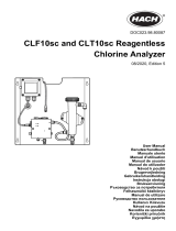
3.2 POWER, ALARM, AND OUTPUT WIRING
Refer to Figure 3-1. Make power and alarm connections on TB3. Make analog output wiring connections on TB2. For
access to power and alarm terminals, loosen the screw holding the protective cover in place and remove the cover.
DANGER
Live voltages may be present.
Will cause severe injury or death.
Alarm contacts are dry (i.e., not powered) and are normally open. Refer to Section 1.0 for relay specifications.
For best EMI/RFI protection, shield the output cable and enclose it in an earth-grounded, rigid, metal conduit.
Connect the outer shield of the output cable to the earth ground connection on TB2 (see Figure 3-1).
Keep sensor and output signal wiring separate from power wiring. Do no run sensor and power cables in the same
conduit or close together in a cable tray.
AC wiring must be 14 gauge or greater. Be sure to connect earth ground from the power cable to the nearby
ground lug. A good earth ground is necessary for proper operation of the controller. Provide a switch or breaker to
disconnect the analyzer from the main power supply. Install the switch or breaker near the analyzer and label it as
the disconnecting device.
WARNING: RISK OF ELECTRICAL SHOCK
AC connections and grounding must comply with UL 508 or local electrical code. DO NOT apply
power to the analyzer until all electrical connections are verified and secure.
NOTE
The Model 54eA analyzer leaves the factory configured for use with the Model 499ADO sensor
(ppm dissolved oxygen). If a 499ADO sensor is NOT being used, turn to Section 5.5 and con-
figure the transmitter for the desired measurement (ppb oxygen, oxygen measured using a
steam-sterilizable sensor, free chlorine, total chlorine, monochloramine, or ozone) before wiring
the sensor to the analyzer. Operating the analyzer and sensor for longer than five minutes while
the analyzer is improperly configured will greatly increase the stabilization time for the sensor.
Be sure to turn off power to the analyzer before wiring the sensor.

9
MODEL 54eA SECTION 3.0
WIRING
FIGURE 3-1. Power Input and Relay Output Wiring for Model 54eA
DWG. NO. REV.
454EPH02 D

10
MODEL 54eA SECTION 3.0
WIRING
FIGURE 3-3. Amperometric sensors
with standard cable.
FIGURE 3-4. Amperometric sensors
with optimum EMI/RFI cable or Variopol cable.
FIGURE 3-2. Wiring Label
3.3 SENSOR WIRING
3.3.1 General
The wiring label, which is shown in Figure 3-2,
is a general purpose label. It has wiring infor-
mation concerning other sensors, for example,
contacting and inductive conductivity sensors,
that can be used with the 54e instrument plat-
form. For amperometric measurements, only
TB3 and TB5 are used. Wire the amperometric
sensor to TB3. Wire the pH sensor, if one is
being used, to TB5.
3.3.2 Wiring Model 499A oxygen, chlorine,
and ozone sensors
All 499A amperometric sensors (499ATrDO,
499ADO, 499ACL-01, 499ACL-02, 499ACL-03,
and 499AOZ) have identical wiring.
Use the pigtail wire and wire nuts provided with
the amperometric sensor when more than one
wire must be attached to a single terminal.
See Figures 3-3 and 3-4.
DWG. NO. REV.
40054e03 A
DWG. NO. REV.
40499A23 A
DWG. NO. REV.
40499A24 A
NOTE
The Model 54eA analyzer leaves the factory configured for use with the Model 499ADO sensor
(ppm dissolved oxygen). If a 499ADO sensor is not being used, turn to Section 5.5 and config-
ure the analyzer for the desired measurement (ppb oxygen, oxygen measured using a steam-
sterilizable sensor, free chlorine, total chlorine, monochloramine, or ozone) before wiring the
sensor to the analyzer. Operating the analyzer and sensor for longer than five minutes while the
analyzer is improperly configured will greatly increase the stabilization time for the sensor.
Be sure to turn off power to the analyzer before wiring the sensor.

11
MODEL 54eA SECTION 3.0
WIRING
3.3.3 Wiring 499ACL-01 (free chlorine) sensors and pH sensors for automatic pH correction.
If free chlorine is being measured using the 499ACL-01 sensor and the pH of the liquid varies more than 0.2 pH
unit, a continuous correction for pH must be applied to the chlorine reading. Therefore, a pH sensor must also be
wired to the 54eA controller. This section gives wiring diagrams for the pH sensors typically used.
When using the 499ACL-01 sensor (free chlorine) with a pH sensor, use the RTD in the pH sensor for meas-
uring temperature. DO NOT use the RTD in the free chlorine sensor.
The pH sensor RTD is needed for temperature measurement during buffer calibration. During normal operation,
the RTD in the pH sensor also provides the temperature measurement required for the free chlorine membrane
permeability correction.
NOTE
When wiring a pH and a 400ACL-01 amperometric sensor to the controller, connect the anode
and reference terminals (TB3-1 and TB5-1) with the 10MΩ jumper (PN 23980-00) provided with
the analyzer.
Refer to the table to select the appropriate wiring diagram. Most of the wiring diagrams require that two or more
shield wires be attached to a single terminal. Use the pigtail wire and wire nuts packed with the chlorine sensor to
make the connection.
Free chlorine sensor cable pH sensor Figure
Standard 399VP-09 3-5
Standard 399-14 3-6
Standard 399-09-62 3-7
EMI/RFI or Variopol 399VP-09 3-8
EMI/RFI or Variopol 399-14 3-9
EMI/RFI or Variopol 399-09-62 3-10
FIGURE 3-5. 499ACL-01 sensor with standard cable
and 399VP-09 pH sensor without internal preamplifier.
DWG. NO. REV.
4054eA01 B

12
MODEL 54eA SECTION 3.0
WIRING
FIGURE 3-6. 499ACL-01 sensor with standard cable and 399-14 pH sensor having internal preamplifier.
FIGURE 3-7. 499ACL-01 sensor with standard cable and 399-09-62 pH without internal preamplifier.
Although the blue wire is connect-
ed to a terminal labeled solution
ground, the blue wire does not
connect to a solution ground in the
sensor. The 399-14 sensor has no
solution ground. The blue wire,
instead, ties the preamplifier in the
sensor to instrument common.
DWG. NO. REV.
4054eA05 A
DWG. NO. REV.
4054eA03 A

MODEL 54eA SECTION 3.0
WIRING
FIGURE 3-9. 499ACL-01 sensor with optimum EMI/RFI cable or
Variopol cable and 399-14 pH sensor having internal preamplifier.
FIGURE 3-8. 499ACL-01 sensor with optimum EMI/RFI cable or Variopol cable
and 399VP-09 pH sensor without internal preamplifier.
13
Although the blue wire is connect-
ed to a terminal labeled solution
ground, the blue wire does not
connect to a solution ground in the
sensor. The 399-14 sensor has no
solution ground. The blue wire,
instead, ties the preamplifier in the
sensor to instrument common.
DWG. NO. REV.
4054eA02 B
DWG. NO. REV.
4054eA06 A

14
MODEL 54eA SECTION 3.0
WIRING
FIGURE 3-10. 499CL-01 sensor with optimum EMI/RFI cable or
Variopol cable and 399-09-62 pH sensor without internal preamplifier.
DWG. NO. REV.
4054eA04 A
3.3.4 Wiring 438ACL-01 (pH independent free chlorine) sensors
FIGURE 3-11. 498CL-01 (pH-independent free chlorine) sensor
/