
Installation and Operation Instructions
Part # A/CTE-50, A/CTE-250,
A/CTV-50, A/CTV-250
AUTOMATION COMPONENTS, INC Version : 1.0
2305 Pleasant View Road Page 1 of 3 I0000141
Middleton, Wisconsin 53562 (888) 967-5224
www.workaci.com
Please Read Instructions Carefully Before Installation!
Safety
This product is not intended to be used for Life or Safety applications.
This product is not intended for use in any hazardous or classified locations.
Disconnect and lock out all power sources before installation as severe injury or death may result from electrical
shock due to contact with high voltage wires.
Installation
Disconnect and lock out all power sources before installation as severe injury or death may result from electrical shock due to
contact with high voltage wires. Make sure that all installations are in compliance with all national and local electrical codes.
Only qualified individuals that are familiar with codes, standards, and proper safety procedures for high-voltage installations
should attempt installation. The current sensor will not require external power, since the power for the current sensor is
induced from the conductor being monitored.
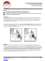
The A/CTE & A/CTV Series Analog Current Sensors should be used on Insulated Conductors Only! The current sensors may
be mounted in any position using the (2) #8 x 3/4” Tek screws and the mounting holes in the base or snapped directly on to the
35mm DIN rail (See Figures 1 & 2 below). Leave a minimum distance of 1” (3 cm) between the current sensor and any other
magnetic devices such as contactors and transformers.
3X
IND.CONT.EQ.
C
LISTED
US
3JHX
Automation Components, Inc.
Middleton, WI
A/CTE-50
ACI
US
C
LISTED
3JHX
IND.CONT.EQ.
Automation Components, Inc.
Middleton, WI
A/CTE-50
ACI
3X
Figure 1: Sensor Placed on Rail Figure 2: Sensor Removed From Rail
Wiring
ACI recommends the use of a 2 conductor 16 to 22 AWG shielded cable, or copper wire only for all Analog current sensor
installations. A maximum wire length of less than 30 meters (98.4 feet) should be used between the A/CTE and A/CTV series
current sensors and the Building Management System or controller. Note: When using a shielded cable, be sure to connect only
(1) end of the shield to ground at the controller. Connecting both ends of the shield to ground may cause a ground loop. When
removing the shield from the sensor end, make sure to properly trim the shield so as to prevent any chance of shorting. The
current sensors terminals are polarity sensitive and represent a linear 0 to 5 or 0 to 10 VDC output signal. The recommended
torque to be used on the terminal block connections is 0.67 Nm or 5.93 in-lbs. The aperture (hole) size of the current sensor is
0.75” (1.90 cm) and will accept a maximum cable diameter of 350 MCM’s.
!

AUTOMATION COMPONENTS, INC Version : 1.0
2305 Pleasant View Road Page 2 of 3 I0000141
Middleton, Wisconsin 53562 (888) 967-5224
www.workaci.com
Operating Specifications
*Note: All current sensors are shipped from the factory with the jumper set in the high range.
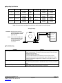
Wiring Example
_
+
Acquisition System
PLC, DDC, or Data
+ 0-5 or 0-10 VDC
(-) Signal Common
GND (Shield)
Analog Input
Connections: Shielded, twisted pair cable is
recommended for these connections.
Note: Ground shield at control
system end only!
Power: These current sensors DO NOT
need an external power source,
since the power is self-induced
from the monitored load
or conductor.
Troubleshooting
Problem
Solution
No reading
- Verify that there is current flowing thru the conductor being monitored with a
clamp-on current probe. The power for the current sensor is induced from the
conductor being monitored.
- Check the polarity of the circuit.
- Verify that the terminals are screwed down, wires are firmly in place.
- Disconnect the wires from the current sensor output. Measure the voltage
across the current sensor output with a Voltmeter to verify that the sensor is
working properly.
Erratic readings
- Verify that the wires are terminated properly.
- In areas of high RF interference, shielded cable may be necessary to stabilize
signal.
Inaccurate readings
- If you suspect that the current sensor is not reading within the accuracy
specifications, please contact the factory for assistance.
ACI Model #
Output
Range
Jumper *
Max. Sensing
Current Voltage
Max. Continuous
Current
Max. Current for
6 seconds
A/CTE-50
0 to 5 VDC
0-10 Amps
0-20 Amps
0-50 Amps
Low
Middle
High
600 VAC
100 Amps
150 Amps
200 Amps
125 Amps
225 Amps
300 Amps
A/CTE-250
0 to 5 VDC
0-100 Amps
0-200 Amps
0-250 Amps
Low
Middle
High
600 VAC
200 Amps
360 Amps
400 Amps
250 Amps
450 Amps
500 Amps
A/CTV-50
0 to 10 VDC
0-10 Amps
0-20 Amps
0-50 Amps
Low
Middle
High
600 VAC
60 Amps
100 Amps
160 Amps
80 Amps
200 Amps
300 Amps
A/CTV-250
0 to 10 VDC
0-100 Amps
0-200 Amps
0-250 Amps
Low
Middle
High
600 VAC
160 Amps
320 Amps
400 Amps
200 Amps
400 Amps
500 Amps

AUTOMATION COMPONENTS, INC Version : 1.0
2305 Pleasant View Road Page 3 of 3 I0000141
Middleton, Wisconsin 53562 (888) 967-5224
www.workaci.com
Current Conversion Formulas
To convert the current sensor output signal to a current reading.
0-10 Volt output to Current reading (0 Volts = 0 Amps and 10 Volts = 250 Amps for A/CTV-250)
Example: 5 Volts current sensor output signal
Total Span = 250 Amps
Multiplier = 10V-0V/Total Span = .04
(5 Volts) / 0.04 = 125 Amps
WEEE Directive
At the end of their useful life the packaging and product should be disposed of via a suitable recycling centre. Do not dispose of
with household waste. Do not burn.
LISTED
C US
IND.CONT.EQ.
3JHX
-
 1
1
-
 2
2
-
 3
3


aci A/CTE-50 Product Instruction
- Type
- Product Instruction
Ask a question and I''ll find the answer in the document
Finding information in a document is now easier with AI
Related papers
-
aci A/MCS-A Installation and Operation Instructions
-
-
-
-
-
-
-
-
-
Other documents
-
Honeywell CSS-C User manual
-
-
Penberthy Model CTE Mixer/Heater Owner's manual
-
Trane Drives Engineering Bulletin
-
Trane ctv-prc007-en User manual
-
-
American Standard CenTraVac Duplex CDHG User manual
-
-
-
Trane GVAF X 250 Installation Operation & Maintenance