Page is loading ...

INSTRUCTION MANUAL
CAUTION: Read All Instructions Before Operating Equipment
MFJ ENTERPRISES, INC.
300 Industrial Park Road
Starkville, MS 39759 USA
Tel: 662-323-5869 Fax: 662-323-6551
COPYRIGHT 2006 MFJ ENTERPRISES, INC.
C
Model MFJ-1796
VERSION 0A
WARC Band Vertical Antenna

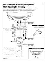
MFJ-1796W WARC Band Vertical Antenna
60 Meter
Ca p a cita nce Sp o ke s (8)
& Loading Coil
30 Meter (4)
17 Meter (4)
12 Meter (4)
Ba lun
Note: This drawing is not to scale
MFJ-1796W
Vertical Antenna
Mounting Bracket
Co a x Co n n e ct o r Asse mb l y
with Drip Loop
1
Always
Follow
Assembly
Instructions!!

MFJ-1796W WARC Band Vertical Antenna
MFJ-1796W (WARC) Vertical Antenna
INTRODUCTION
The basic 60 meter quarter wave vertical antenna is 44' tall and requires a reasonably good
ground or counterpoise system to function properly. The usual way to eliminate the requirement
for a complicated and space consuming ground system is to center feed a 1/2 wave (in this
example 88' tall) antenna.
MFJ solved these problems by combining efficient end loading with a balanced center feedpoint
design. The result is a physically small vertical antenna that gives good performance and does
not require any type of RF ground system.
The reduction in size is accomplished by adding separate loading coils and capacitance hats at
each end of the antenna for the HF bands. The efficient end loading coils are wound on
fiberglass forms. The high quality materials and construction of the HF loading system allows a
maximum power rating of 1500 watts on 60, 30, 17 and 12 meters. The continuous CW power
ratings are 500 watts on 60 meters, 750 watts on 30 or 12 meters and 1000 watts on 17 meters.
WARNING: Improper installation and assembly can be hazardous! Read these instructions
thoroughly before attempting to assemble, install or operate this product! High power
transmitting devices produce voltages that can cause severe burns or other injuries.
CHOOSING A LOCATION FOR THE ANTENNA
The best performance on receiving and transmitting will be obtained by mounting the antenna in
a clear location above or away from buildings, towers, feedlines, utility wires, and other
antennas. While your own ingenuity and particular circumstances will determine the final
mounting method, we'll pass along a few ideas for both permanent installation and portable
operation.
Never mount this antenna in a location that will permit unsuspecting people to come in contact
with the loading spokes or any other part of the antenna.
Never mount this antenna where a mechanical failure might allow the antenna to contact power
lines or other utility wires.
Always ground the feedline at the point where it enters a building to a good earth ground for
lightning protection.
WARNING Always mount this antenna so that it is out of the reach of adults as well as
children. The capacitance elements can cause injury and or severe RF burns.
Permanent Installation
The ideal installation is a rigid pole or roof mount that puts the antenna completely in the clear.
If the ideal installation is not possible, choose the best compromise. TV mast, heavy-duty rigid

MFJ-1796W WARC Band Vertical Antenna
electrical conduit, or steel water pipe are suitable mast materials. This antenna will mount on
masts between 1 and 1-1/2" OD. The use of soft or thin wall masts is not recommended
The MFJ-1796W will perform quite well even at ground level, which means the lower
capacitance hat should be at least 5 ft above ground level on a short rigid mast. However, the
antenna installation MUST be protected (with non-metallic fencing) to provide personal safety
and to prevent damage to the antenna itself.
Portable Operation
This antenna may be disassembled to the extent necessary for transporting to a temporary
location. If possible, only remove the two HF loading coil assemblies. Leave the two main
elements with the 2 and 6 meter stub assemblies intact. Some retuning may be required after
moving the antenna.
Even for temporary or portable operation, do not be casual about selecting a suitable mast. If the
antenna falls it will be damaged and may cause serious injury. Whatever type of installation you
choose, remember that the antenna should be installed where it can never be contacted by people
or animals.
TOOLS AND TIME REQUIRED FOR ASSEMBLY
The estimated assembly time for this antenna is two hours. Antenna assembly requires the
following hand tools:
1/4" nut driver
3/8" open end wrench
5/16" nut driver (or 1/4" blade standard screwdriver)
7/16" nut driver
7/16" open end wrench
Large wire cutters
#1 phillips screwdriver at least 6" long or longer
#2 phillips screwdriver
suitable eye protection
In addition, you will need two stable supports at least 30" tall (such as saw horses or trash cans)
and a short (6-8') temporary mast (1 to 1-1/2" OD) for temporary mounting during tuning.
MFJ-1796W PARTS LIST
As you unpack your antenna you should find the parts in the following list.
[ ] 2 Fiberglass Coil Assemblies
[ ] two bundles of wire capacitance spokes 28 short, 12 medium, (and 4 spare long spokes)
[ ] one bag of clamps 10 hose clamps and 2 saddle bolts
[ ] 5' upper radiator, 6061-T6 AL tubing, 1 1/8" OD with the 6 and 2 meter stubs inside
[ ] 5' lower radiator, 6061-T6 AL tubing, 1 1/8" OD (this tube has two holes through it)

MFJ-1796W WARC Band Vertical Antenna
[ ] one bag of short 6-32 stainless screws (you will only use 40, the rest are extra)
[ ] 4 small "L" brackets with holes one end
[ ] 4 long "U" channel "L" brackets
[ ] 4 flat fiberglass insulators
[ ] 2 hollow white nylon insulators
[ ] 1 solid rod fiberglass center insulator
[ ] 5 split ring 1/4" washers
[ ] 5 1/4" dia. 7/16" head bolts
[ ] 5 1/4-20 x 7/16" nuts
[ ] 20 6-32 x 1/2" stainless screws
[ ] 20 6-32 x 1/4" nuts
[ ] 8 10-32 x 3/8 nuts
For installation you will need some items not supplied with the antenna installation kit.
[ ] A 6'-8' rigid mast or other mounting pipe between 1" and 1.5" outside diameter. (suitable
materials include TV mast sections, galvanized iron pipe, or heavy duty rigid conduit.)
[ ] Quality low-loss 50-Ohm coax with a PL-259 from antenna to transmitter.
[ ] Either a SWR meter or Analyzer (MFJ-207 or MFJ-249)
SAFETY PRECAUTIONS:
WARNING! You can be killed if the antenna, feedline, or the equipment used to install the
antenna accidentally contacts any utility lines. Never install an antenna near power lines!
1. Be careful while climbing and carrying the antenna. It is heavy enough to cause you to lose your
balance if it is handled too casually or if the capacitance spokes are snagged on a gutter, ladder,
tree limbs and so forth.
2. Mount the antenna high enough so that it is out of reach. The ends of the capacitance spokes can
cause eye injury, serious RF burns or both.
3. Make sure that the mast is sturdy enough to support the 15 pounds weight and the wind load of
approximately 2 square feet.
ASSEMBLY and INSTALLATION PROCEDURE
During assembly of this antenna refer to the figures in this manual and the picture on Page 1.
The assembly instructions tell you how to first install the balun and then connect the upper and
lower elements. Last the loading coil assemblies are assembled and installed on the upper and
lower elements.
After the antenna is assembled it is checked and adjusted for resonant frequency and SWR. It
can then be mounted on a tower or rooftop and given final adjustments.
NOTE: Wear safety glasses whenever working near or on this antenna.

MFJ-1796W WARC Band Vertical Antenna
Warning: Do not tighten the screws that connect the loading coil terminal lugs to the
capacitance hats or you will BREAK the fiberglass form. If the terminal lugs
loosen tighten the NUT down on the lug.
Step-By-Step Procedure
[ ] 1. Prepare a temporary ground-level mounting mast that will permit easy initial testing and
adjustment. Set up saw horses or any other stable support (plastic trash cans or folding
tables, etc.) near the mast.
[ ] 2a. Sort out the parts you have unpacked into groups of similar parts. Be sure all the parts are
available.
[ ] 3. After examining the antenna parts, gather the tools needed for basic assembly. At the
minimum these consist of:
[ ] #1 Long Phillips screwdriver for capacitance spoke screws
[ ] #2 Phillips screwdriver for other 6-32 screws
[ ] 1/4" standard screwdriver or a 5/16" nut driver for hose clamps.
[ ] 3/8" wrench for 6 and 2 meter stub nuts
[ ] Two 7/16" open end wrenches or one wrench and one nut driver for "U" BOLTS and
center insulator bolts.
[ ] Wire cutters for trimming capacitance spokes.
[ ] Safety glasses.
IMPORTANT: Do not use a high torque electric screwdriver to mount the capacitance
spokes. The screw heads will be sheared off if too much torque is applied.
[ ] 4. Bolt the top balun hole loosely to the top hole in the base mounting assembly with a 1/4-
20 x 7/16" nut and the 1/4" x 7/16" head bolts. Use the hollow white nylon spacers to
separate the balun from the mounting bracket. Finger tighten only. See Figure 2.
[ ] 5. Bolt the bottom balun hole to the bottom hole in the base mounting assembly as in Step 5.
[ ] 6. Tighten the balun bolts with a 7/16" wrench.
[ ] 7. Bolt the coax connector assembly to the base mounting assembly with four 6-32 x 5/8"
screws and 6-32 nuts. See Figure 2.
[ ] 8. Slide the bottom radiator (the one with two sets of holes) over the fiberglass rod with the
holes that are 2" from the end toward the base mounting bracket. Slide a hose clamp to
the bottom of the element. The radiator should butt against the insulating plastic of the
base mounting bracket. Install a 1/4 x 7/16" bolt through the element and fiberglass rod
and tighten with a lock washer and 1/4 x 7/16" nut.
[ ] 9. Tighten the hose clamp installed in step 9 over the slit in the bottom element. This clamp
will make the antenna more rigid.

MFJ-1796W WARC Band Vertical Antenna
[ ] 10. Insert the fiberglass center insulator into the bottom element and insert a 1/4" x 7/16" head
bolt with a lock washer through the hole. Thread a 1/4" x 7/16" nut on the other end.
Finger tighten only. See Figure 3. Slide a hose clamp over the center insulator. Tighten
the hose clamp on the slit in the bottom element. Slide another hose clamp over the
insulator.
[ ] 11. Slide the top 1" diameter element over the center insulator and install the 1/4" x 7/16"
head bolt and nut as in step 10. Tighten the hose clamp over the slit in the top element
until the element will not sway.
[ ] 12. Install the short 6-32 screws in the ring of both loading coil assemblies away from the
hose clamps and brackets. Do not thread the screws completely in. Put the long
capacitance spokes in the six holes in these rings on both coil assemblies. Tighten the
screws until the spokes are snug. At this point you should be able to turn the coil
assemblies over and they should balance on the long spokes. USE THE #1 PHILLIPS
SCREWDRIVER HERE.
[ ] 13. Install the screws in the next set of rings and install six short spokes in these rings.
[ ] 14. Install the next groups of four spokes on each loading coil assembly.
[ ] 15. Check the bare wires running along the side of the loading coil assembly to be sure that
there is at least 1" of clearance between the bare wire and the capacitance spokes. It is
okay to bend the bare wire enough to clear the spokes properly. See Figure 7.
[ ] 16. Remove the nuts on the center insulator bolts of the main element and install the center
conductor lug of the coax under the upper element nut and the shield lug under the
bottom element nut. Hold the nut in place and turn the bolt head to tighten these bolts so
that the lug does not break off the end of the coax. Be sure to dress the coax so it loops up
in a drip loop so water cannot get into the end. See Figure 8.
[ ] 17. Use the three wire ties to affix the coax to the antenna as illustrated on page 1. Do not
allow the coax to come within 1 inch of the base mounting bracket.
[ ] 18. Slide a hose clamp over the top element. Mount the top coil assembly to the antenna by
inserting the fiberglass insulator in the top element. Tighten the bus wire from the coil
assembly under the hose clamp.
[ ] 19. Mount the coil assembly with the angle mounting bracket four inches from the bottom
insulator of the antenna.
[ ] 20. Double check the tightness of all the hardware you installed and then mount the antenna
on the short temporary tuning mast.
[ ] 21. Tune the antenna, see the next section.

MFJ-1796W WARC Band Vertical Antenna
[ ] 22. Mount the antenna in it's permanent location. Slight re-tuning may be necessary.
FREQUENCY AND SWR ADJUSTMENT
This antenna covers wider frequency ranges on the higher bands, and narrower segments on the
lower frequency bands. The 60 meter band has the narrowest range of operation (approximately
20 KHz) and is the most sensitive to adjustments.
The entire antenna must be accessible during initial coarse tuning and testing. Any repair or
adjustment to the antenna after it is installed on a tall support will make adjustments difficult and
time consuming. It is best to install the antenna on a short temporary mast or pipe that is located
in a reasonably clear location for tuning. The antenna should be mounted vertically with the
base of the antenna around six feet above ground to make tests and adjustments easy.
The SWR can be measured by using a transmitter and SWR bridge or an SWR Analyzer. The
best location to make SWR measurements is at the base of the antenna. If the measurements are
not taken at the base of the antenna, the antenna must be fed with a reasonably short length of
good quality 50 ohm coaxial cable to insure proper results. If using a transceiver and SWR
meter, set the transceiver to the lowest power possible to make measurements.
The normal resonant frequency of this antenna is at or just below the bottom of each
amateur band. This allows the user to "trim" a small amount off the inside end of the
capacitance spokes to raise the resonant frequency. Conversely, adding a longer capacitance
spoke will lower the resonant frequency of a loading assembly. Spare spokes are included in
case you need to lower the resonant frequency of the antenna.
CAUTION: Always start tuning on 60 meters and adjust each band progressively higher in
frequency. Adjustment of a lower frequency band will always have the most effect on the next
higher frequency band. The tendency of the interaction is that if you move one band higher ALL
the other bands move higher, but only very slightly. It is always best to "shoot for" the lowest
end of the range you intend to use and "trim in" by adjusting the bottom loading assembly after
the antenna is in it's final location. ALWAYS work from the bottom band up.
Tuning the Antenna
1. Measure and record the frequency that the lowest SWR occurs on for each band. The lowest
SWR should be at or below the bottom end of each HF band. The SWR should be below 2:1 at
resonance on each band.
The following is a typical chart for initial measurements of a new antenna before tuning:
60 M 2.5:1 at 5.0 MHz 17 M 1.7:1 at 17.8 MHz
30 M 1.6:1 at 9.7 MHz 12 M 1.7:1 at 24.8 MHz
If the resonant frequency is lower than your equipment can detect take one spoke off to raise the
resonant frequency. Measure the resonant frequency and calculate the approximate resonant
frequency as if the spoke was in place using the chart on the next page.

MFJ-1796W WARC Band Vertical Antenna
The following tips will help you obtain an even better SWR on 5.3 MHz than the tuning method
used on other bands. On 60 meters the lowest SWR is usually not obtained with the top and
bottom loading spokes adjusted to the same frequency.
60 Meters: If you desire operation below 6 MHz the lowest SWR will be obtained by adding
two extra long spokes to the bottom 60 meter loading coil assembly. It is best to add the spokes
on opposite sides of the coils, closest to the horizontal as possible (perpendicular to the vertical
element.) Short 60 meter spokes from both coils can then be trimmed equal amounts to resonate
the antenna. This will leave the bottom loading assembly with two spokes that are longer than
the top.
Begin tuning by trimming one 40 meter spoke from each end of the antenna by cutting off
small, equal sections from the inside end of the spoke until the antenna resonates approximately
15 KHz below the desired operating frequency. Use the chart below to approximate the amount
of spoke to be trimmed. Trimming only one spoke from the top or bottom results in half the
frequency change.
60 M: 1" trimmed off a pair of spokes equals approximately 20 KHz
30 M: 1" trimmed off a pair of spokes equals approximately 100 KHz
17 M: 1" trimmed off a pair of spokes equals approximately 175 KHz
12 M: 1" trimmed off a pair of spokes equals approximately 250 KHz
2. If the SWR is acceptable at the desired operating frequency the adjustment for that band may be
skipped.
3. Now tune progressively higher frequency bands by trimming pairs of spokes(one top one
bottom). Keep each pair of capacitance spokes equal in size. 30 meters must be the second HF
band adjusted, 17 the third and 12 meters last. After adjusting 12 meters go back and check the
other bands. Tighten all spoke screws.
4. Final frequency adjustments can be made by trimming spokes on the bottom hat only when the
antenna is permanently mounted. The minor adjustment of bottom spokes without the
symmetrical trimming of the top spokes is perfectly acceptable so long as the frequency is
changed less than 30 KHz on 60 meters and 60 KHz on the higher bands with the final
adjustment. The result of attempting to move the resonant frequency too far with only the
bottom spokes will be an increase in the SWR of the antenna at the resonant frequency.
NOTE: The spokes can also be bent toward another spoke in the same mounting ring to raise
the frequency slightly without cutting.
GROUNDING CONSIDERATIONS
Although this antenna is designed to operate efficiently without the requirement of an earth
ground, SAFETY GROUNDING MUST STILL be provided to protect equipment, property and
persons from the hazards of lighting strikes and other weather related electrical discharges. In
addition the coaxial cable feeding the antenna should have the shield grounded to eliminate the
risk of any indoor equipment failure from allowing hazardous voltages from appearing indoors
and creating a shock hazard.

MFJ-1796W WARC Band Vertical Antenna
Adequate protection can be accomplished by grounding the shield of the coax where it enters the
building to a good earth ground or directly burying the cable in the earth for several feet before
it enters the building. The coaxial cable should be totally disconnected from the station during
threatening weather conditions for maximum lightning protection.
A less effective method of protecting station equipment is to install an in-line coaxial lightning
arrestor with a heavy duty ground wire to a suitable earth ground, or a safety switching system as
part of the basic ham station equipment.
MAINTENANCE
Your antenna is constructed of heavy duty non corrosive materials and should withstand normal
climates for many years. The use of some type of coaxial connector moisture protection is
recommended at the bottom coax connection and also around the center-feed connections,
especially in coastal areas where salty mist is commonplace.
GE makes a pure silicone grease called "SILICONE DIALECTRIC COMPOUND" that can be
applied SPARINGLY to the threaded area of the female connector. This compound, or even a
clear silicone heatsink compound, will prevent moisture from entering the connector through the
threads and protect the connectors from corrosion. THIS IS THE SAME TYPE OF SEALER
THAT COMMERCIAL ANTENNA INSTALLERS AND CATV COMPANIES USE WITH
GREAT SUCCESS. A less desirable, but still adequate sealer is the automobile seam sealer
commonly sold as "coax seal". This is a semi-pliable black sealing compound.
When installing any "coax seal", NEVER completely cover the barrel of the coax connector. The
sealer should ONLY be placed near the junction of the threaded part of the chassis connector and
the knurled area of the male connector. This will leave the bottom of the male outer sleeve open
and permit the connector to "breathe" so it does NOT collect moisture!
TECHNICAL ASSISTANCE
If you have any problem with this unit first check the appropriate section of this manual. If the
manual does not reference your problem or your problem is not solved by reading the manual,
you may call MFJ Technical Service at 662-323-0549 or the MFJ Factory at 662-323-5869.
You will be best helped if you have your unit, manual and all information on your station handy
so you can answer any questions the technicians may ask. You can also send questions by mail
to MFJ Enterprises, INC., 300 Industrial Park Road, Starkville, MS 39759; by Facsimile (FAX)
to 662-323-6551; or by email to [email protected]. Send a complete description of
your problem, an explanation of exactly how you are using your unit, and a complete description
of your station and a daytime telephone number.

MFJ-1796W WARC Band Vertical Antenna
FULL 12-MONTH WARRANTY
MFJ Enterprises, Inc. warrants to the original owner of this product, if manufactured by MFJ Enterprises,
Inc. and purchased from an authorized dealer or directly from MFJ Enterprises, Inc. to be free from
defects in material and workmanship for a period of 12 months from date of purchase provided the
following terms of this warranty are satisfied.
1. The purchaser must retain the dated proof-of-purchase (bill of sale, canceled check, credit
card or money order receipt, etc.) describing the product to establish the validity of the warranty
claim and submit the original or machine reproduction of such proof of purchase to MFJ
Enterprises, Inc. at the time of warranty service. MFJ Enterprises, Inc. shall have the discretion to
deny warranty without dated proof-of-purchase. Any evidence of alteration, erasure, of forgery
shall be cause to void any and all warranty terms immediately.
2. MFJ Enterprises, Inc. agrees to repair or replace at MFJ's option without charge to the
original owner any defective product provided the product is returned postage prepaid to MFJ
Enterprises, Inc. with a personal check, cashiers check, or money order for $10.00 covering
postage and handling.
3. MFJ Enterprises, Inc. will supply replacement parts free of charge for any MFJ product
under warranty upon request. A dated proof of purchase and a $8.00 personal check, cashiers
check, or money order must be provided to cover postage and handling.
4. This warranty is NOT void for owners who attempt to repair defective units. Technical
consultation is available by calling (662) 323-5869.
5. This warranty does not apply to kits sold by or manufactured by MFJ Enterprises, Inc.
6. Wired and tested PC board products are covered by this warranty provided only the
wired and tested PC board product is returned. Wired and tested PC boards installed in the
owner's cabinet or connected to switches, jacks, or cables, etc. sent to MFJ Enterprises, Inc. will be
returned at the owner's expense unrepaired.
7. Under no circumstances is MFJ Enterprises, Inc. liable for consequential damages to
person or property by the use of any MFJ products.
8. Out-of-Warranty Service: MFJ Enterprises, Inc. will repair any out-of-warranty product
provided the unit is shipped prepaid. All repaired units will be shipped COD to the owner. Repair
charges will be added to the COD fee unless other arrangements are made.
9. This warranty is given in lieu of any other warranty expressed or implied.
10. MFJ Enterprises, Inc. reserves the right to make changes or improvements in design or
manufacture without incurring any obligation to install such changes upon any of the products
previously manufactured.
11. All MFJ products to be serviced in-warranty or out-of-warranty should be addressed to
MFJ Enterprises, Inc., 300 Industrial Park Rd, Starkville, Mississippi 39759, USA and must
be accompanied by a letter describing the problem in detail along with a copy of your dated proof-
of-purchase and a telephone number.
12. This warranty gives you specific rights, and you may also have other rights, which vary
from state to state.

MFJ-1796W Manual
Version 0A
Printed In U.S.A.
300 Industrial Park Road
Starkville, MS 39759
MFJ ENTERPRISES, INC.
/