13
Added effect types
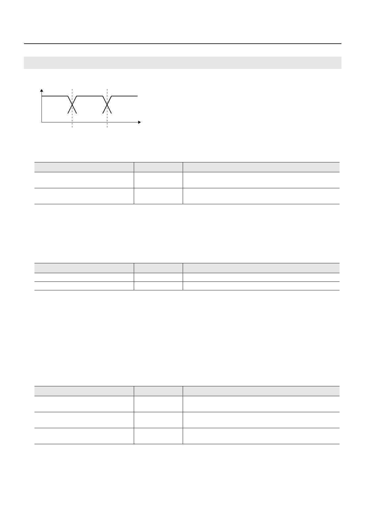
◆SPLIT : Splits the original sound into three frequency bands (low, middle, and high)
• Splitting into bands
When splitting sound into high, midrange, and low bands, the frequencies are specified by the low-split point
(SPLIT LO) and high-split point (SPLIT HI).
◆INPUT
• Input "look-ahead time" effect
With an ordinary compressor, a momentary delay occurs before compression starts after an exceeded level is
detected.
This algorithm is intended to avoid this problem by using only detection of the input-sound level to use sound
delayed by a specified amount for actual processing and output.
The delay-time setting for this is input look-ahead time (LOOK-AHEAD).
Applying look-ahead time creates a time lag between input and output audio signals, and so care is required when
using it with channel insertion or the like.
◆MIX (mixer) : Adjusts the volume level of the individual frequency bands
INPUT
Parameter (name) Setting value Remarks
SPLIT LO (low split point) 20 – 800Hz
Frequency for splitting the original sound into 3 bands (low
end)
SPLIT HI (high split point) 1.60 – 16.00kHz
Frequency for splitting the original sound into 3 bands (high
end)
Parameter (name) Setting value Remarks
LEVEL (input level) -24.0 – 12dB Overall volume level before entering expander/compressor
LOOK-AHEAD (look-ahead time) 0.0 – 50ms Time by which the original sound input is delayed
Parameter (name) Setting value Remarks
LO MIX (low mix level) -Inf – 6.0dB
Volume level of the low band after passing through the LO
MIX (low-mix level) expander and compressor
MID MIX (middle mix level) -Inf – 6.0dB
Volume level of the middle band after passing through the
MID MIX (middle-mix level) expander and compressor
HI MIX (high mix level) -Inf – 6.0dB
Volume level of the high band after passing through the HI
MIX (high-mix level) expander and compressor
Freq
L-SplitP H-SplitPLevel
Low Mid High


