
3
3M
™
Electronic Marking System (EMS)
iD Ball Marker
Installation Instructions
1.0 Introduction
1.1 3M
™
iD Ball Markers provide an accurate,
convenient, long lasting method of marking
underground facilities during construction or
maintenance. They also make the job of precisely
locating underground facilities easier. Other
buried markers can be disturbed by backfill
dirt or installed improperly so they don't stay
positioned correctly. The 3M iD Ball Markers
unique self-leveling design ensures the marker is
in an accurate, horizontal position regardless of
how it is placed into the ground. 3M iD Markers
enable you to return to the exact location of the
marked underground feature and ensure positive
identification by reading the stored data and unique
serial number in each iD Marker. Unlike surface
markers such as stakes, flags or paint, the iD Ball
marker cannot be inadvertently moved or worn
away by weather.
2.0 Removable Identification Number Tag
2.1 Prior to burying the iD Marker, remove the
identification number tag and attach it to
“as-builts”, or facility documentation, as required
by company procedure.
3.0 Writing Information to iD Markers
3.1 Second generation iD Markers launched in the
first quarter of 2012. Please make sure your
3M
™
Dynatel
™
iD Enabled Locator has the latest
software. The latest PC-Tools can be downloaded
at www.3m.com/dynatel.
3.2 If the iD marker is intended to contain specific
facility information, write the information to
the iD marker prior to burying using one of the
3M
™
Dynatel
™
iD enabled locators (see list below).
3.3 Hold the 3M
™
Dynatel
™
M-Series iD Locator
receiver over the top of the iD marker. The
maximum distance between the marker and the
locator tip during writing is 12 in. (30 cm).
3.4 For iD Marker writing instructions, please refer
to the following Operator’s Manuals: 3M
™
Dynatel
™
EMS-iD Locator 1420, 3M
™
Dynatel
™
Cable/Pipe/Fault Locator 2250M/2273M Series
or 3M
™
Dynatel
™
Cable/Pipe/Fault Locator
2550/2573 Series.
4.0 Installing the iD Marker
4.1 Before placing the iD Marker over the key point
of the facility, decide if a tie down procedure is
necessary to keep it in place. If so, secure the iD
Marker by inserting a cable tie through one, or
both, tie down tabs on the iD Marker and the key
point (for example, pipe, cable or splice).
4.2 If the key point is metallic, it is recommended that
the iD Marker be separated from it by a minimum
distance of 4 inches (10 cm) of clean fill dirt.
4.3 If the key point in non-metallic, place the iD
Marker over the desired location.
IMPORTANT: The iD Ball Marker cannot reliably
re-radiate the locator's signal at a depth greater than 5
feet (1.5 m). If using an E-model locator in countries
following CE limitations, or equivalent, the maximum
depth is 4 feet (1.2 m). This is the maximum allowable
distance between iD Ball Marker and the locator tip.
4.4 Hand fill at least 6 inches (15 cm) of soil over
the iD Marker to prevent movement, or damage,
during backfill.
4.5 Backfill the hole.
February 2014
78-8130-6423-1 Rev F

3M and Dynatel are trademarks of 3M Company.
3
Electrical Markets Division
6801 River Place Blvd.
Austin, TX 78726-9000
1-800-200-0265
Fax: 1-877-601-1305
http://www.3M.com/dynatel
Please Recycle. Printed in USA.
© 3M 2014. All Rights Reserved.
78-8130-6423-1 Rev F
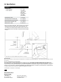
5 ft. (1.5 m)
maximum
separation
*4 ft. (1.2 m)
maximum
with E-Model Locator
cover with 6 in.
(15 cm) of firm
soil before backfill
tie-down
tabs
ID number
tag
Inset
minimum 4 in.
(10 cm) separation
from metallic surface
cable
tie
See inset
*Max depth for Power and Water iD Markers with an E-Model is 1 meter (40 in).
5.0 Specifications
Specifications
Read Depth (max)
Locator, US-Version
Locator, E-Version
5 ft ( 1.5 m)
1.2 m (48 in)
(Telephone, Gas,
Waste Water,
Communication)
1.0 m (40 in)
(Power,Water)
Program Distance (max) 12 in (30 cm)
Vertical Separation from Facility (min) 4 in* (10.4 cm)
Horizontal Separation from Facilty (min) 4 in* (10.4 cm)
Distance Between iD Markers (min) 3.5 ft (1.06 m)
Marker Diameter, Sphere 4 in (10.4 cm)
* Target size and material dependent. Depth estimation may be adversely
affected when placing the marker above a large metallic object, such
as a manhole cover. To improve depth estimation accuracy, increase the
vertical separation from the metal object or perform a field test for depth
accuracy.
Important Notice
Before using this product, you must evaluate it and determine if it is suitable for your intended application. You assume all risks and liability associated
with such use.
Warranty; Limited Remedy; Limited Liability.
3M’s product warranty is stated in its Product Literature available upon request. 3M MAKES NO OTHER WARRANTIES INCLUDING, BUT
NOT LIMITED TO, ANY IMPLIED WARRANTY OF MERCHANTABILITY OR FITNESS FOR A PARTICULAR PURPOSE. If this product
is defective within the warranty period stated above, your exclusive remedy shall be, at 3M’s option, to replace or repair the 3M product or refund the
purchase price of the 3M product. Except where prohibited by law, 3M will not be liable for any indirect, special, incidental or consequential loss
or damage arising from this 3M product, regardless of the legal theory asserted.
-
 1
1
-
 2
2


Ask a question and I''ll find the answer in the document
Finding information in a document is now easier with AI
Other documents
-
3M EMS Mini-Marker 1258, Wastewater Installation guide
-
3M Full-Range Marker 1252-XR/iD, 8 ft Range, Water Operating instructions
-
3M Disk Marker 1411-XR, 5 ft Range, Telephone, Not Operating instructions
-
3M Ball Marker 1407-XR, EMS 6 ft Extended Range, Communications Operating instructions
-
3M EMS Mini-Marker 1256, Power Operating instructions
-
-
-
-
-