3
3M
Electronic Marking System (EMS)
Extended Range (XR) Ball Marker
Installation Instructions
1.0 Introduction
1.1 3M
Extended Range (XR) Ball Markers provide
an accurate, convenient, long lasting method of
marking underground facilities during construction
or maintenance. They also make the job of
precisely locating underground facilities easier.
Other buried markers can be disturbed by backfill
dirt or installed improperly so they don’t stay
positioned correctly. The 3M XR Ball Markers
unique self-leveling design ensures the marker is in
an accurate, horizontal position regardless of how
it is placed into the ground. 3M markers enable
you to return to the exact location of the marked
underground feature. Unlike surface markers such
as stakes, flags or paint, the XR Ball Marker cannot
be inadvertently moved or worn away by weather.
2.0 Installing the XR Ball Marker
2.1 Before placing the XR Ball Marker over the key
point of the facility, decide if a tie down procedure
is necessary to keep it in place. If so, secure the
marker by inserting a cable tie through one, or
both, tie down tabs on the Marker and the key point
(for example, pipe, cable or splice).
2.2 If the key point is metallic, it is recommended that
the marker be separated from it by a minimum
distance of 4 inches (10 cm) of clean fill dirt.
2.3 If the key point in non-metallic, place the marker
over the desired location.
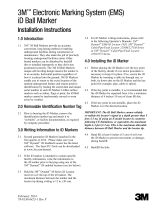
IMPORTANT: The XR Ball Marker cannot reliably
re-radiate the locator's signal at a depth greater than
5 feet (1.5 m). This is the maximum allowable distance
between Ball Marker and the locator tip.
February 2014
78-8128-0476-9 Rev C
5 ft. (1.5 m)
maximum
separation
cover with 6 in.
(15 cm) of firm
soil before backfill
tie-down
tabs
Inset
minimum 4 in.
(10 cm) separation
from metallic surface
cable
tie
See inset
3M and Dynatel are trademarks of 3M Company.
3
Electrical Markets Division
6801 River Place Blvd.
Austin, TX 78726-9000
1-800-200-0265
Fax: 1-877-601-1305
http://www.3M.com/dynatel
Please Recycle. Printed in USA.
© 3M 2014. All Rights Reserved.
78-8128-0476-9 Rev C
2.4 Hand fill at least 6 inches (15 cm) of soil over the
marker to prevent movement, or damage, during
backfill.
2.5 Backfill the hole.
3.0 Specifications
Specifications
Read Depth (max)
Locator, US-Version
Locator, E-Version
5 ft (1.5 m)
1.5 m (5 ft)
Vertical Separation from Facility (min) 4 in* (10.4 cm)
Horizontal Separation from Facilty (min) 4 in* (10.4 cm)
Distance Between iD Markers (min) 3.5 ft (1.06 m)
Marker Diameter, Sphere 4 in (10.4 cm)
* Target size and material dependent. Depth estimation may be adversely
affected when placing the marker above a large metallic object, such
as a manhole cover. To improve depth estimation accuracy, increase the
vertical separation from the metal object or perform a field test for depth
accuracy.
Important Notice
Before using this product, you must evaluate it and determine if it is suitable for your intended application. You assume all
risks and liability associated with such use.
Warranty; Limited Remedy; Limited Liability.
3M’s product warranty is stated in its Product Literature available upon request. 3M MAKES NO OTHER WARRAN-
TIES INCLUDING, BUT NOT LIMITED TO, ANY IMPLIED WARRANTY OF MERCHANTABILITY OR
FITNESS FOR A PARTICULAR PURPOSE. If this product is defective within the warranty period stated above, your
exclusive remedy shall be, at 3M’s option, to replace or repair the 3M product or refund the purchase price of the 3M prod-
uct. Except where prohibited by law, 3M will not be liable for any indirect, special, incidental or consequential loss or
damage arising from this 3M product, regardless of the legal theory asserted.
  • Page 1 1
  • Page 2 2