
WFM6100, WFM7000, and WFM7100
Waveform Monitors
System Integration Technical Reference
Revision A
Warning
The service instructions are for use by qualified personnel only.
To avoid personal injury, do not perform any s ervicing unless
you are qualified to do so. Refer to all safety summaries prior
to performing service.
www.tektronix.com
071-1983-01

Copyright © Tektronix. All rights reserved. Licensed software products are owned by Tektronix or its subsidiaries
or suppliers, and are protected by national copyright laws and international treaty provisions.
Tektronix products are covered by U.S. and foreign patents, issued and pending. Information in this publication
supersedes that in all previously published material. Specifications and price change privileges reserved.
TEKTRONIX a nd TEK are registered trademarks of Tektronix, Inc.
Contacting Tektronix
Tektronix, Inc.
14200 SW Karl Braun Drive
P.O. B o x 5 0 0
Beaverton, O
R 97077
USA
For product information, sales, service, and technical support:
In North America, call 1-800-833-9200.
Worldwide, visit www.tektronix.com to find contacts in your area.

Table of Contents
General Safety Summary .......................................................................................... ii
Service Safety Summary.......................................................................................... iv
Preface ............................................................................................................... v
Related User D
ocuments...................................................................................... v
Related Reference Documents .............................................................................. vi
System Integration.................................................................................................. 1
Installation Considerations.................................................................................... 5
Power and Environmental Specifications ................................................................... 6
Connector Specifications...................................................................................... 8
Rackmount In
stallation....................................................................................... 17
Network Operation ........................................................................................... 21
WFM6100, WFM7000, and WFM7100 Waveform Monitors i

General Safety Summary
General Safet
ySummary
Review the fol
lowing safety precautions to avoid injury and prevent da mage to
this product or any products connected to it.
To avoid pote
ntial hazards, use this product only as specified.
Only qualified pe rsonnel should perform service procedures.
To Avoid Fire
or Person al
Injury
Use Proper Power Cord. Use only the power cord specified for this product and
certified for the country of use.
Connect and Disconnect Properly. Do not connect or disconnect probes or test
leads while they are connected to a voltage source.
Ground the Product. This product is grounded through the grounding conductor
of the power cord. To avoid electric shock, the grounding conductor must be
connected to earth ground. Before making connections to the input or output
terminals of the product, ensure that the product is properly grounded.
Observe All Terminal Ratings. To avoid fire or shock hazard, observe all ratings
and markings on the product. Consult the product manual for further ratings
information before making connections to the product.
Do not apply a potential to any terminal, including the common terminal, that
exceeds the maximum rating of that terminal.
Power Disconnect. The power cord disconnects the product from the power source.
Donotblockthepowercord;itmustremain accessible to the user at all times.
Do Not Operate Without Covers. Do not operate this product with covers or panels
removed.
Do Not Operate With Suspected Failures. If you suspect that there is damage to this
product, have it inspected by qualified service personnel.
Avoid Exposed Circuitry. Do not touch exposed connections and components
when power is present.
Do Not Operate in Wet/Damp Conditions.
Do Not Operate in an Explosive Atmosphere.
Keep
Product Surfaces Clean and Dry.
Provide Proper Ventilation. Refer to the manual’s installation instructions for
details on installing the product so it has p roper ventilation.
ii WFM6100, WFM7000, and WFM7100 Waveform Monitors

General Safety Summary
Terms in this Manual
These terms may
appear in this manual:
WARNING. Warning s tatements identify conditions or practices that could result
in injury or loss of life.
CAUTION. Caution statements identify conditions or practices that could result in
damage to this product or other property.
Symbols and Terms on the
Product
These terms may appear on the product:
DANGER ind
icates an injury hazard immediately accessible as you read
the marking.
WARN ING i
ndicates an injury hazard not immediately accessible as you
read the marking.
CAUTION i
ndicates a hazard to property including the product.
The following symbol(s) may appear on the product:
WFM6100, WFM7000, and WFM7100 Waveform Monitors iii

Service Safety Summary
Service Safet
y Summary
Only qualified
personnel should perform service procedures. Read this Service
Safety Summary and the General Safety Summary befor e performing any service
procedures.
Do Not Service Alone. Do not perform internal service or adjustments of this
product unless another p erson capable of rendering first aid and resuscitation is
present.
Disconnect Power. To avoid e lectric shock, switch off the instrument power, then
disconnect the power cord from the mains power.
Use Care When Servicing With Power On. Dangerous voltages or currents may
exist in t
his p roduct. Disconnect power, remove battery (if a pplicable), and
disconnect test leads before removing protective panels, soldering, or replacing
components.
To avoid electric shock, do not touch e xposed connections.
iv WFM6100, WFM7000, and WFM7100 Waveform Monitors

Preface
Preface
This document
is provided as an aid for system integrators who are designing
systems for high-definition (HD) and standard-definition (SD) digital video
content where the Tektronix WFM6100, WFM7000, and WFM7100 Waveform
Monitors are to be deployed.
Tektronix provides many products designed to
test, measure, and monitor analog
and digital video/audio signals. These products include waveform m onitors,
audio monitors, signal generators, and video measurement sets. For M PEG
video signals, Tektronix also provides test systems, transport stream monitors ,
players/recorders, and portable analyzers.
Related User Documents
The following table lists the related user documents for the WFM6100,
WFM7000, and W FM7100 Waveform Monitors. The table also indicates whether
the document is printed, and whether the PDF of the document is available only
on the Tektronix Web site (www.tektronix.com) or also on the User Documents
CD that accompanies the printed Quick Start User Manual.
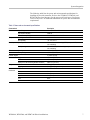
Table i: Related user documents
Availability
Document Tektronix part number Description Print Web CD
Release Notes 071-1895-XX Describes any known problems or behaviors
that you might encounter while using the
waveform monitor.
Quick Start User
Manual
020-2705-XX (English)
020-2706-XX (Japanese)
020-2707-XX (Chinese)
This document is a printed Quick Start User
Manual and contains the basic operating
information for the instrument. Included in the
manual is a CD-ROM containing PDFs of the
user documents.
User Technical
Reference
071-1894-XX
Contains the detailed operating information
for the instrument.
Specifications
and Performance
Verification Technical
Reference
071-1897-XX
Contains the complete published
specifications for the instrument and
the performance verification procedure.
Service Manual
071-1896-XX
Provides servicing information for the
instrument and is intended for qualified
service personnel only.
Management
Information Base
(MIB) Technical
Reference
071-1592-XX
Contains information about using the
Management Information Base (MIB) to
control the instrument.
WFM6100, WFM7000, and WFM7100 Waveform Monitors v

Preface
Related Refer
ence Documents
The following table lists the related reference documents for the WFM6100,
WFM7000, and WFM7100 Waveform Monitors. The table also indicates
whether the P
DF of the document is available only on the Tektronix Web site
(www.tektronix.com) or also on the User Documents CD that accompanies the
printed Quick Start User Manual.
Table ii: Related reference documents
Availability
Document Description Web CD
Preventing Illegal Colors
This application note describes how the D iamond, Arrowhead, and
Lightning displays can be used to help prevent the undesired impact of
color gamut violations and to simplify the assessment of proper gamut
compliance.
Understanding Colors and Gamut This poster provides a large visual display of how the Diamond, Arrowhead,
and Lightning displays can be used to help prevent the undesired impact of
color gamut violations.
A Guide to Standard and
High Definition Digital Video
Measurements
This book is a primer for understanding the basics for making standard and
high-definition, digital-video measurements.
Analog and Digital Audio
Monitoring
This application note describes how to monitor analog and digital audio
signals. Also discussed are specific differences in the methods used to
monitor analog audio versus digital audio, and how to plan the transition
from monitoring analog audio to monitoring digital audio.
Audio Monitoring This application note describes balanced and unbalanced audio signals,
and explains the physical and electrical characteristics and the specific
strength and weaknesses of the different digital audio signal formats.
Monitoring Surround Sound Audio This application note describes the basics of 5.1-channel surround sound
audio and tells how to use the Surround Sound display to visualize key
audio-level and phase relationships in this audio format.
NTSC Video Measurements This book is a primer for understanding the basics for making NTS C video
measurements.
PA L S ystems Television
Measurements
This book is a primer for understanding the basics for making PAL video
measurements.
vi WFM6100, WFM7000, and WFM7100 Waveform Monitors

System Integration
The WFM6100, WFM7000, and WFM7100 Waveform Monitors offer the
monitoring capabilities needed in the production, post-production, distribution,
and transmis
sion of high-definition (HD) and standard-definition (SD) digital
video content. With available digital audio monitoring support, you can expand
the capabilities to monitor both digital video and audio in a single instrument.
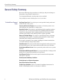
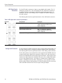
The following table lists the available waveform monitor models. The illustrations
on the following pages show the front panel of the waveform monitor, and also
show the rear panel of the waveform monitor when Option EYE or PHY is not
installed and when one of the two options is installed. The location of the SDI
video connectors changes when Option EYE or PHY is installed.
Table 1: W
aveform monitor models
Model Usage Features
WFM6100 For quality assessment and control
in video p
roduction, distribution
and broadcast systems using SD
digital video
Extended
event logging and video/audio session screens
Triggere
d data capture
Automate
d quality checking with Te ktronix certification of quality
Optional
digital and analog audio monitoring
WFM7000 For basic quality assessment
in video p
roduction and
post-production applications
using HD digital video formats or in
mixed SD
/HD environments
Two SDI vi
deo inputs compatible with SMPTE292M (with a vailable
support for SMPTE259M formats), loop-through external reference,
switched video outputs, picture monitor output
Fault monitoring, alarm generation, and basic event logging
Waveform, vector, gamut, picture and timing displays, including Split
Diamond
, Arrowhead, and Lightning
Standar
d graticules and time/voltage cursors
Ancilla
ry data detection, including decoding of closed caption
information
Optional digital and analog audio monitoring
WFM7100 For qual
ity assessment and control
in video production, distribution,
and broadcast systems using HD
digital
video formats or in mixed
SD/HD environments
WFM7000
capabilities plus:
Extende
d event logging and video/audio session screens
Trigger
ed data capture
Automate
d quality checking with Te ktronix certification of quality
Tektroni
x quality dashboard with Red light/Green light status displays
WFM6100, WFM7000, and WFM7100 Waveform Monitors 1

System Integration
NOTE. You can lo
cate copies of some of the illustrations from this document in
JPEG format on the Tektronix We b site (www.tektronix.com) and on the User
Documents CD that accompanies the WFM6100, WFM7000, and WFM7100
Quick Start User Manual.
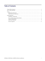
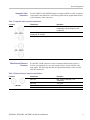
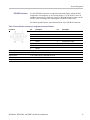
The following illustrations are available: Figure 1, Figure 2, Figure 3, Figure 10,
Figure 11, and Figure 12.
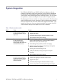
Figure 1: Front panel
2 WFM6100, WFM7000, and WFM7100 Waveform Monitors

System Integration
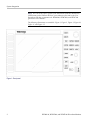
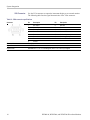
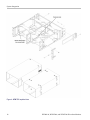
Figure 2
: Rear panel without Option EYE or PHY installed
WFM6100, WFM7000, and WFM7100 Waveform Monitors 3

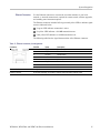
System Integration
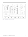
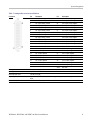
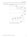
Figure 3
: Rear panel with Option EYE or PHY installed
4 WFM6100, WFM7000, and WFM7100 Waveform Monitors

System Integration
Installation
Considerations
The waveform monitor is shipped in a wrap-around chassis that covers the
instrument bottom and two sides. A cover is installed on the chassis, and the rea r
panel is made
up of the module rear p anels.
You can ope rate the waveform monitor in the instrument chassis (be sure the top
cover is on) o
r installed in an approved portable cabinet or rack adapter. (See
page 17, Rackmount Installation.) You can also install the waveform monitor in a
custom installation, such as a console.
CAUTION. To prevent damage to the waveform monitor and the cabinet, do not
install the waveform monitor in any cabinet except those that are approved by
Tektronix, such as the WFM7F02 and WFM7F05.
If you ins
tall the waveform monitor in a custom application, such as a console, be
sure to provide adequate airflow. Follow these guidelines:
Do not bl
ock the ventilating holes.
Adhere to the clearance requirements. (See Table 2 on page 7.)
System
Installation
The waveform monitor can operate almost anywhere in the video distribution
system. To monitoring the video bitstream of a serial receiver, route the incoming
serial signal into one of the waveform monitor SDI inputs.
To monitor serial digital signals around a routing switcher, connect your serial
sources through a patch panel to a serial router. Connect the output of the serial
route
r to an SDI input for comparison.
Line Termination
The waveform monitor uses passive loop-through analog and reference inputs.
Accordingly, the loop-through must be terminated externally. It is important that
thi
s external t ermination meet accuracy and return loss requirements.
If the waveform monitor is installed to monitor an operating link, the destination
re
ceiver and the connecting cable serve as the termination. This monitoring
connection is best because it checks the performance of the entire path. The
return loss of the waveform monitor is sufficiently high that, in most cases, the
destination receiver sets the system return loss.
In cases where the waveform monitor is placed at the end of a link, a BNC
termination must be installed on one side of the loop-through analog or reference
connector. The termination must be 75 Ω and DC coupled (good return loss
extendstoDC).Returnlossshouldexceed40dBfromDCto6MHzfor
composite. An appropriate terminator would be Canare part number BCP-TA. It
is a 75 Ω, 1%, BNC, 26 dB return loss to 2 GHz, end-of-line termination.
WFM6100, WFM7000, and WFM7100 Waveform Monitors 5

System Integration
Compatibility of BNC
Center Pins
Most video equi
pment BNC connectors, whether 50 Ω or 75 Ω,usea50Ω
standard center pin. Some laboratory 75 Ω BNC connectors use a smaller diameter
center pin. The BNC connectors on the waveform monitor are designed to work
with the 50 Ω s t andard (large diameter) center pins.
CAUTION. To prevent intermittent signal connections, do not use connectors or
terminators with the smaller diameter center pins.
Power and Environmental Specifications
The wavefo
rm monitor operates from a single-phase power source with the neutral
conductor at or near earth ground. The line conductor is fused for over-current
protection. A protective ground connection through the grounding conductor in
the power cord is essential for safe operation.
NOTE. Power systems with both current-carrying conductors live with respect
to ground (such as phase-to-phase in multiphase systems) are not recommended
as power
sources.
The waveform monitor does not need any power configuration, except for
using the proper power cord for your installation site. Refer to the WFM6100,
WFM700
0, and WFM7100 Waveform Monitors Quick Start User Manual for a list
of the available power cords.
To con
nect power to the waveform monitor, insert the supplied power cord into
the rear-panel power connector. There is no power switch on the waveform
monitor, so the instrument will turn on as soon as you apply power.
6 WFM6100, WFM7000, and WFM7100 Waveform Monitors

System Integration
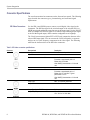
The following t
able lists the power and environmental specifications for
installing the waveform monitor. Refer to the WFM6100, WFM7000, and
WFM7100 Waveform Monitors Specifications and Performance Verification
Technical Reference for additional information on power and environmental
requirements.
Table 2: Power and environmental specifications
Characteristic Description
Input Voltage
100 to 240 VAC ± 10%
Input Power Frequency
50/60 Hz
Power
Power Consumption, typical 50 to 110 VA at 110 or 240 VAC
Operating 0 °C to +40 °C
Temperature
Non-operating
-20°Cto+60°C
Operating 20% to 80% relative humidity (% RH) at up to +40 °C,
non-condensing
Humidity
Non Operating 5% to 90% RH (relative humidity) at up to +60 °C,
non-condensing
Altitude
Operating 3,000 m (9,842 ft)
Non-operating
12,192 m (40,000 ft)
Pollution Degree 2, Indoor use only
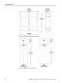
Height
133.4 mm (5.25 in)
Width
215.9 m m (8.5 in)
Dimensions
Depth (front to back including handles and BNCs) 460.4 mm (18.125 in)
Net
5.5kg(12lbs)
Weight
Shipping 9.6 kg (21 lbs) approximately
Top None
Bottom None
Leftside 2in(51mm)
Right side
2in(51mm)
Front None
Required
Clearances
Rear
2in(51mm)
WFM6100, WFM7000, and WFM7100 Waveform Monitors 7

System Integration
Connector S pe
cifications
The waveform monitor has connectors on the front and rear panels. The following
pages describe the connector types, pin numbering, and associated signal
requirement
s.
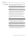
SDI Video Connectors
Use the SDI A and SDI B inputs to connect a serial digital video signal to the
instrument. The SDI Out signal is the switched output of the selected SDI A or
SDI B input s
ignal and has the same data rate as the input signal. Use the IN/OUT
menu to configure the SDI Out signal to be either the looped-through input signal
or the Pix Mon signal output, which contains configurable error brightups.
The Clock Out connector (Option EYE or PHY only) outputs the data rate of the
selected SDI input signal. You can connect the Clock Out s ignal to a spectrum
analyzer to view jitter frequency components in the video signal. The following
table lists the characteristics of the SDI video connectors.
Table 3: SDI video connector specifications
Connector Characteristic Description
Input Type
BNC, 75 Ω internally terminated
Input Level
800 mV ± 10%
Cable Loss Accommodation: SD
0 to 30 dB attenuation
Equivalent to approximately 300 m of
Belden 8281 at 270 Mb/s
With 1/SQ RT(f) characteristic at 1/2 of serial
rate
Cable Loss Accommodation: HD
0 to 20 dB attenuation
Equivalent to approximately 80 m of
Belden 8281 at 1.485 Gb/s. Typical
performance to 110 m
With 1/SQ RT(f) characteristic at 1/2 of serial
rate
Output Type BNC, 75 Ω internally terminated
Output Level 800 mV ± 10% into 75 Ω load
Output Type (Option EYE/PHY only) Reference clock; BNC, 1 V p-p into 75 Ω load
Output Frequency SD = 27 MHz
HD = 74.25 or 74.17852 MHz
8 WFM6100, WFM7000, and WFM7100 Waveform Monitors

System Integration
Composite Video
Connectors
Use the CMPST A a
nd CMPST B inputs to connect an NTSC or PAL, composite
video signal to the instrument. The following table lists the s ignal characteristics
of the composite video connectors.
Table 4: Composite video connector specifications
Connector Characteristic Description
Input Type; Quantity BNC, passive loop-through, 75 Ω
compensated; 2 inputs (Composite A and
Composite B)
Maximum Operating Amplitude with
Clamping Off (DC Coupled)
-1.8 V to +2.2 V, DC + peak AC
Maximum Absolute Input Voltage
-6.0 V to +6.0 V, DC + peak AC
Video External Reference
Connector
Use the REF LOOP connector to input a composite Black Burst signal or a
tri-level sync signal for use as a sync timing refe r ence for the selected video
input s
ignal. The following table lists the signal characteristics of the external
reference connectors.
Table 5: External reference connector specifications
Connector Characteristic Description
Input Type
BNC, passive loop-through, 75 Ω
comp
ensated
Input Level -6 to +6 dB
Maximum Input Voltage Level
±5V,DC
Maximum Absolute Input Voltage
±5V,DC
WFM6100, WFM7000, and WFM7100 Waveform Monitors 9

System Integration
AES Digital Audio
Connectors
Use the AES audi
o connectors to input or output digital audio signals. The "A"
connectors are input only. You can configure the "B" connectors to function as
an additional input or as an output of the audio signal being input on the "A"
connectors. Use the Audio Settings menu to configure the channel m apping in
the audio displays.
The following table lists the signal characteristics of the AES Audio connectors.
Table 6: AES digital audio connector specifications
Connector Characteri
stic
Descriptio
n
Input Type (
A and B connectors)
BNC, 75 Ω ter
minated, unbalanced
(meets requirements of AES 3-ID and
SMPTE 276M-1995)
Input Amplitude Range (A and B connectors)
0.1 V
p-p
to 2 V
p-p
Output Type (B connectors only) BNC, 75 Ω terminated, unbalanced
(meets req
uirements of AES 3-ID and
SMPTE 276M-1995)
Output Amplitude Range (B connectors only) 0.9 V to 1.1 V Pk-Pk into 75 Ω
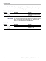
Analog Audio Connecto r
Use th
e ANALOG AUDIO connector to input or output analog audio signals. Use
the Audio Settings menu to configure the channel mapping in the audio displays.
The following table lists the signal characteristics of the Analog Audio connector.
For all audio options except Option DS, use the supplied 62-pin DSUB connector
to attach analog-audio signals to the instrument. Solder wires to the connector as
needed to accommodate the desired audio inputs and outputs. Audio signals can be
connected as either balanced or unbalanced. Be sure to use a suitable cable when
you are wiring balanced audio. An example of a suitable cable is Belden 8451,
whi
ch is a shielded twisted pair cable. Alternatively, you can purchase an audio
breakout cable (Tektronix part number 012-1688-00), which provides a two meter
cable with XLR c onnectors for all twelve inputs and eight outputs.
10 WFM6100, WFM7000, and WFM7100 Waveform Monitors

System Integration
Table 7: Analog
audio connector specifications
Connector Pin Description Pin Description
1
Ch. 1 input, line A, positive
22
Ch. 1 input, line A, negative
2
Ch. 1 input, line B, positive
23
Ch. 1 input, line B, negative
3
Ch. 2 input, line A, positive
24
Ch. 2 input, line A, negative
4
Ch. 2 input, line B, positive
25
Ch. 2 input, line B, negative
5
Ch. 3 input, line A, positive
26
Ch. 3 input, line A, negative
6
Ch. 3 input, line B, positive
27
Ch. 3 input, line B, negative
7
Ch. 4 input, line A, positive
28
Ch. 4 input, line A, negative
8
Ch. 4 input, line B, positive
29
Ch. 4 input, line B, negative
9
Ch. 5 input, line A, positive
30
Ch. 5 input, line A, negative
10
Ch. 5 input, line B, positive
31
Ch. 5 input, line B, negative
11
Ch. 6 input, line A, positive
32
Ch. 6 input, line A, negative
12
Ch. 6 input, line B, positive
33
Ch. 6 input, line B, negative
13
Ground
34
Ground
14
Ch. 1 output, positive
35
Ch. 1 output, negative
15
Ch. 2 output, positive
36
Ch. 2 output, negative
16
Ch. 3 output, positive
37
Ch. 3 output, negative
17
Ch. 4 output, positive
38
Ch. 4 output, negative
18
Ch. 5 output, positive
39
Ch. 5 output, negative
19
Ch. 6 output, positive
40
Ch. 6 output, negative
20
Ch. 7 output, positive
41
Ch. 7 output, negative
21
Ch. 8 output, positive
42
Ch. 8 output, negative
43-62 Not Used
Characte
ristic
Description
Input Type
62 pin, 3
row, DSUB, balanced, unterminated
Maximum Input Level +24 dBu ± 0.3 dBu
Output Type 62 pin, 3 row, DSUB, balanced, unterminated; ground negative output to support unbalanced
mode
Maximum
Output Level
+24 dBu ±
0.5 dBu (designed to drive a ≥ 600 Ω load)
WFM6100, WFM7000, and WFM7100 Waveform Monitors 11

System Integration
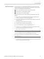
Remote Connector
Use the Remote c
onnector to input LTC time code signals, and to remotely select
one of the first four instrument presets in group "A" using ground closure. The
following table lists the s ignal characteristics of the Remote connector.
Table 8: R emote connector pin assignments and specifications
Connector Pin Description Direction Notes
1
Ground Out
2
Time Code+
In
LTC time code input
3
Time Code-
In
LTC time code input
4
Ground Out
5
Ground Closure Output Out Open collector output
6 Preset Recall A1 In
Ground this pin to select preset A1
7
Preset Recall A2 In
Ground this pin to select preset A2
8 Preset Recall A3 In
Ground this pin to select preset A3
9 Preset Recall A4 In
Ground this pin to select preset A4
Characteristic
Description
LTC Input Connector 9 pin DSUB, balanced, unterminated
LTC Input Signal Longitudinal Time Code per IEC Publication 461
LTC Signal Amplitude Range 0.2 V
p-p
to 5.0 V
p-p
balanced differential or single-ended
Ground Closure Input Signal
TTL thresholds, 5 V m ax input, -0.5 min input; pull low to assert
Ground Closure Output Signal One open collector output
12 WFM6100, WFM7000, and WFM7100 Waveform Monitors
Page is loading ...
Page is loading ...
Page is loading ...
Page is loading ...
Page is loading ...
Page is loading ...
Page is loading ...
Page is loading ...
Page is loading ...
Page is loading ...
Page is loading ...
-
 1
1
-
 2
2
-
 3
3
-
 4
4
-
 5
5
-
 6
6
-
 7
7
-
 8
8
-
 9
9
-
 10
10
-
 11
11
-
 12
12
-
 13
13
-
 14
14
-
 15
15
-
 16
16
-
 17
17
-
 18
18
-
 19
19
-
 20
20
-
 21
21
-
 22
22
-
 23
23
-
 24
24
-
 25
25
-
 26
26
-
 27
27
-
 28
28
-
 29
29
-
 30
30
-
 31
31


Tektronix WFM6100 Opt. MB Technical Reference
- Type
- Technical Reference
- This manual is also suitable for
Ask a question and I''ll find the answer in the document
Finding information in a document is now easier with AI
Related papers
-
Tektronix WFM7100 Opt. MB User manual
-
-
-
-
-
-
-
-
-
