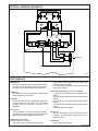
Danfoss S90 P is an electrical displacement control that offers precise and responsive control of swashplate angle in Danfoss Series 90 Pumps. With its two-stage electrohydraulic design, it provides closed-loop control for accurate positioning and smooth operation. Key capabilities include:
-
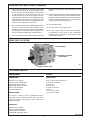
Precise Control: The S90 P utilizes a torque-motor actuated pilot stage and a unique spool arrangement to achieve accurate control of pump output, ensuring consistent performance and precise flow regulation.
-
Null Deadband: The device features a null deadband, which provides a safety feature by preventing unintended pump movement near the neutral position. This deadband ensures that the pump remains stationary when the control signal is near zero, enhancing safety and preventing unwanted system movements.
Danfoss S90 P is an electrical displacement control that offers precise and responsive control of swashplate angle in Danfoss Series 90 Pumps. With its two-stage electrohydraulic design, it provides closed-loop control for accurate positioning and smooth operation. Key capabilities include:
-
Precise Control: The S90 P utilizes a torque-motor actuated pilot stage and a unique spool arrangement to achieve accurate control of pump output, ensuring consistent performance and precise flow regulation.
-
Null Deadband: The device features a null deadband, which provides a safety feature by preventing unintended pump movement near the neutral position. This deadband ensures that the pump remains stationary when the control signal is near zero, enhancing safety and preventing unwanted system movements.


-
 1
1
-
 2
2
-
 3
3
-
 4
4
-
 5
5
-
 6
6
-
 7
7
-
 8
8
-
 9
9


Danfoss S90 P is an electrical displacement control that offers precise and responsive control of swashplate angle in Danfoss Series 90 Pumps. With its two-stage electrohydraulic design, it provides closed-loop control for accurate positioning and smooth operation. Key capabilities include:
-
Precise Control: The S90 P utilizes a torque-motor actuated pilot stage and a unique spool arrangement to achieve accurate control of pump output, ensuring consistent performance and precise flow regulation.
-
Null Deadband: The device features a null deadband, which provides a safety feature by preventing unintended pump movement near the neutral position. This deadband ensures that the pump remains stationary when the control signal is near zero, enhancing safety and preventing unwanted system movements.
Ask a question and I''ll find the answer in the document
Finding information in a document is now easier with AI
Related papers
-
Danfoss S42 P Installation guide
-
Danfoss MCV104A1922 Installation guide
-
Danfoss H1 P User guide
-
-
-
Danfoss S90 P Installation guide
-
-
-
-