Nilfisk-ALTO Scrubtec R 6-71 28D User manual
- Category
- Scrubber
- Type
- User manual
This manual is also suitable for

08/12 Updated 08/14 Form No. 56043159
Service Manual
Clarke
®
model numbers:
56114000 Focus II Rider 28 D Base
56114001 Focus II Rider 34 D OBC Base
56114002 Focus II Rider 34 D Base
56114003 Focus II Rider 28 B Base
56114009 Focus II Rider 28 B OBC Base
56114010 Focus II Rider 28 D OBC Base
Nilfisk-Alto model numbers:
56114004 Scrubtec R 6-71 28D
56114005 Scrubtec R 6-71C 28C
56114006 Scrubtec R 6-86 34D
56114008 Scrubtec R 6-100 40D
English
Clarke Focus II Rider Autoscrubber
Nilfisk-Alto Scrubtec R6 Rider Autoscrubber

Contents iiService Manual – Focus II / Scrubtec R6 Rider Autoscrubber
Contents
General Informaon . . . . . . . . . . . . . . . . . . . . . . . . . . . . . . . . . . . . . . . . . . . . . .6
Service Manual Purpose and Applicaon . . . . . . . . . . . . . . . . . . . . . . . . . . . . . . . . . 6
Revision History . . . . . . . . . . . . . . . . . . . . . . . . . . . . . . . . . . . . . . . . . . . . . . . 6
Other Reference Manuals and Informaon Sources. . . . . . . . . . . . . . . . . . . . . . . . . . . .6
Convenons. . . . . . . . . . . . . . . . . . . . . . . . . . . . . . . . . . . . . . . . . . . . . . . . . .6
Cauons and Warnings . . . . . . . . . . . . . . . . . . . . . . . . . . . . . . . . . . . . . . . . . . . 6
Symbols . . . . . . . . . . . . . . . . . . . . . . . . . . . . . . . . . . . . . . . . . . . . . . . . . . . . . . 6
General Safety Instrucons . . . . . . . . . . . . . . . . . . . . . . . . . . . . . . . . . . . . . . . . . . . . 7
Transporng the Machine . . . . . . . . . . . . . . . . . . . . . . . . . . . . . . . . . . . . . . . . . . 8
Nameplate . . . . . . . . . . . . . . . . . . . . . . . . . . . . . . . . . . . . . . . . . . . . . . . . . . 9
Know Your Machine — Major components: . . . . . . . . . . . . . . . . . . . . . . . . . . . . . . . . 9
General Specicaons . . . . . . . . . . . . . . . . . . . . . . . . . . . . . . . . . . . . . . . . . . . 10
Fastener Torque Specicaons . . . . . . . . . . . . . . . . . . . . . . . . . . . . . . . . . . . . . . 11
Maintenance Schedule. . . . . . . . . . . . . . . . . . . . . . . . . . . . . . . . . . . . . . . . . . . 11
Lubricang the Machine . . . . . . . . . . . . . . . . . . . . . . . . . . . . . . . . . . . . . . . . . . . . 12
Diagnosc and Service Tools . . . . . . . . . . . . . . . . . . . . . . . . . . . . . . . . . . . . . . . . . . 12
Chassis System . . . . . . . . . . . . . . . . . . . . . . . . . . . . . . . . . . . . . . . . . . . . . . . . 15
Funconal Descripon . . . . . . . . . . . . . . . . . . . . . . . . . . . . . . . . . . . . . . . . . . . 15
Control System . . . . . . . . . . . . . . . . . . . . . . . . . . . . . . . . . . . . . . . . . . . . . . . . 16
Funconal Descripon . . . . . . . . . . . . . . . . . . . . . . . . . . . . . . . . . . . . . . . . . . . 16
Control Panel . . . . . . . . . . . . . . . . . . . . . . . . . . . . . . . . . . . . . . . . . . . . . . . . . . 16
Main Machine Controller . . . . . . . . . . . . . . . . . . . . . . . . . . . . . . . . . . . . . . . . . . . . 17
Component Locaons . . . . . . . . . . . . . . . . . . . . . . . . . . . . . . . . . . . . . . . . . . . 18
Main Machine Controller Programming . . . . . . . . . . . . . . . . . . . . . . . . . . . . . . . . . 19
Programming Menu Outline . . . . . . . . . . . . . . . . . . . . . . . . . . . . . . . . . . . . . . . . . . 19
Quick Start: Navigang the Hidden Menus . . . . . . . . . . . . . . . . . . . . . . . . . . . . . . . 20
Deck Type . . . . . . . . . . . . . . . . . . . . . . . . . . . . . . . . . . . . . . . . . . . . . . . . . . . . 20
Baery Charger . . . . . . . . . . . . . . . . . . . . . . . . . . . . . . . . . . . . . . . . . . . . . . . . . 20
Chemical (Detergent) Selecon. . . . . . . . . . . . . . . . . . . . . . . . . . . . . . . . . . . . . . . . . 20
Detergent Mode . . . . . . . . . . . . . . . . . . . . . . . . . . . . . . . . . . . . . . . . . . . . . . . . . 20
Vacuum Selecon . . . . . . . . . . . . . . . . . . . . . . . . . . . . . . . . . . . . . . . . . . . . . . . . 21
Low Voltage Cutout . . . . . . . . . . . . . . . . . . . . . . . . . . . . . . . . . . . . . . . . . . . . . . . 21
Max (Maximum) Scrub Speed . . . . . . . . . . . . . . . . . . . . . . . . . . . . . . . . . . . . . . . . . 21
Lockout Brush Pre (Pressure) . . . . . . . . . . . . . . . . . . . . . . . . . . . . . . . . . . . . . . . . . . 21
Lockout Sol (Soluon) Flows . . . . . . . . . . . . . . . . . . . . . . . . . . . . . . . . . . . . . . . . . . 21
Chemical (Detergent) Rate Bias . . . . . . . . . . . . . . . . . . . . . . . . . . . . . . . . . . . . . . . . 21
Deck Down Time. . . . . . . . . . . . . . . . . . . . . . . . . . . . . . . . . . . . . . . . . . . . . . . . . 21
Restore Defaults . . . . . . . . . . . . . . . . . . . . . . . . . . . . . . . . . . . . . . . . . . . . . . . . . 21
Display Rev Level . . . . . . . . . . . . . . . . . . . . . . . . . . . . . . . . . . . . . . . . . . . . . . . . 22
Fault Recall. . . . . . . . . . . . . . . . . . . . . . . . . . . . . . . . . . . . . . . . . . . . . . . . . . . . 22
Fault Detecon . . . . . . . . . . . . . . . . . . . . . . . . . . . . . . . . . . . . . . . . . . . . . . . . . 22
Service Test Mode . . . . . . . . . . . . . . . . . . . . . . . . . . . . . . . . . . . . . . . . . . . . . . . . 22
Backup Alarm Vol (Volume). . . . . . . . . . . . . . . . . . . . . . . . . . . . . . . . . . . . . . . . . . . 22
FWD Alarm Vol (Forward) . . . . . . . . . . . . . . . . . . . . . . . . . . . . . . . . . . . . . . . . . . . 22
Horn Volume . . . . . . . . . . . . . . . . . . . . . . . . . . . . . . . . . . . . . . . . . . . . . . . . . . . 22
Panel Test . . . . . . . . . . . . . . . . . . . . . . . . . . . . . . . . . . . . . . . . . . . . . . . . . . . . 22
Troubleshoong Guide. . . . . . . . . . . . . . . . . . . . . . . . . . . . . . . . . . . . . . . . . . . 22
Main Controller Error Codes . . . . . . . . . . . . . . . . . . . . . . . . . . . . . . . . . . . . . . . . . . 23

Contents iiiService Manual – Focus II / Scrubtec R6 Rider Autoscrubber
Service Test Mode . . . . . . . . . . . . . . . . . . . . . . . . . . . . . . . . . . . . . . . . . . . . . . . . 25
Test Mode Display . . . . . . . . . . . . . . . . . . . . . . . . . . . . . . . . . . . . . . . . . . . . . 25
Test Mode Funcons . . . . . . . . . . . . . . . . . . . . . . . . . . . . . . . . . . . . . . . . . . . . 25
Sample Shop Voltage Measurements . . . . . . . . . . . . . . . . . . . . . . . . . . . . . . . . . . . . . 26
Controller I/O Table . . . . . . . . . . . . . . . . . . . . . . . . . . . . . . . . . . . . . . . . . . . . 28
Removal and Installaon. . . . . . . . . . . . . . . . . . . . . . . . . . . . . . . . . . . . . . . . . . 29
Main Control Board . . . . . . . . . . . . . . . . . . . . . . . . . . . . . . . . . . . . . . . . . . . . . . . 29
Electrical System . . . . . . . . . . . . . . . . . . . . . . . . . . . . . . . . . . . . . . . . . . . . . . . 30
Funconal Descripon . . . . . . . . . . . . . . . . . . . . . . . . . . . . . . . . . . . . . . . . . . 30
Safety Circuit. . . . . . . . . . . . . . . . . . . . . . . . . . . . . . . . . . . . . . . . . . . . . . . . . . . 30
Descripon Of The Low-Voltage Cutout Feature . . . . . . . . . . . . . . . . . . . . . . . . . . . . . . . 31
Onboard Baery Chargers . . . . . . . . . . . . . . . . . . . . . . . . . . . . . . . . . . . . . . . . . 31
Interlock Circuit . . . . . . . . . . . . . . . . . . . . . . . . . . . . . . . . . . . . . . . . . . . . . . . 31
S.P.E. Charging Proles and Charging Progress . . . . . . . . . . . . . . . . . . . . . . . . . . . . . 31
Delta-Q Charging Proles and Charging Progress . . . . . . . . . . . . . . . . . . . . . . . . . . . . 32
Delta-Q Baery Charging Prole Table . . . . . . . . . . . . . . . . . . . . . . . . . . . . . . . . . . . . 32
Component Locaons . . . . . . . . . . . . . . . . . . . . . . . . . . . . . . . . . . . . . . . . . . . 34
Maintenance and Adjustments . . . . . . . . . . . . . . . . . . . . . . . . . . . . . . . . . . . . . . 35
Charging Baeries. . . . . . . . . . . . . . . . . . . . . . . . . . . . . . . . . . . . . . . . . . . . . . . . 35
Extending Baery Life. . . . . . . . . . . . . . . . . . . . . . . . . . . . . . . . . . . . . . . . . . . . . . 35
Troubleshoong . . . . . . . . . . . . . . . . . . . . . . . . . . . . . . . . . . . . . . . . . . . . . . 36
Baery Tesng. . . . . . . . . . . . . . . . . . . . . . . . . . . . . . . . . . . . . . . . . . . . . . . . . . 36
Removal and Installaon. . . . . . . . . . . . . . . . . . . . . . . . . . . . . . . . . . . . . . . . . . 36
Baeries . . . . . . . . . . . . . . . . . . . . . . . . . . . . . . . . . . . . . . . . . . . . . . . . . . . . . 36
Electrical Panel Cover . . . . . . . . . . . . . . . . . . . . . . . . . . . . . . . . . . . . . . . . . . . . . . 37
Specicaons . . . . . . . . . . . . . . . . . . . . . . . . . . . . . . . . . . . . . . . . . . . . . . . . 37
Wet Cell Baery Specicaons: . . . . . . . . . . . . . . . . . . . . . . . . . . . . . . . . . . . . . . . . 37
Wet Cell Baery Charger Specicaons . . . . . . . . . . . . . . . . . . . . . . . . . . . . . . . . . . . . 37
Wiring Diagrams . . . . . . . . . . . . . . . . . . . . . . . . . . . . . . . . . . . . . . . . . . . . . . 37
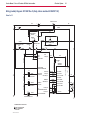
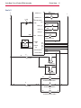
Wiring (Ladder) Diagram: 56114061 Rev C (Early, before machine SN 3000167142) . . . . . . . . . . . 38
Sheet 1 of 2 . . . . . . . . . . . . . . . . . . . . . . . . . . . . . . . . . . . . . . . . . . . . . . . . . 38
Sheet 2 of 2 . . . . . . . . . . . . . . . . . . . . . . . . . . . . . . . . . . . . . . . . . . . . . . . . . 39
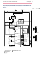
Wiring (Ladder) Diagram 56114404 Rev A (Late, beginning with machine SN 3000167142) . . . . . . 40
Sheet 1 of 2 . . . . . . . . . . . . . . . . . . . . . . . . . . . . . . . . . . . . . . . . . . . . . . . . . 40
Sheet 2 of 2 . . . . . . . . . . . . . . . . . . . . . . . . . . . . . . . . . . . . . . . . . . . . . . . . . 41
Wiring Harness Diagram: 56114062 Rev B (Early, before machine SN 3000167142) . . . . . . . . . . . 42
Wiring Harness Diagram: 56114405 Rev A (Late, beginning with machine SN 3000167142) . . . . . . 43
Connector Pinouts . . . . . . . . . . . . . . . . . . . . . . . . . . . . . . . . . . . . . . . . . . . . . 44
Opons and Accessories . . . . . . . . . . . . . . . . . . . . . . . . . . . . . . . . . . . . . . . . . . . 47
Recovery System . . . . . . . . . . . . . . . . . . . . . . . . . . . . . . . . . . . . . . . . . . . . . . . 48
Funconal Descripon . . . . . . . . . . . . . . . . . . . . . . . . . . . . . . . . . . . . . . . . . . . 48
Vacuum Motor and Recovery Tank. . . . . . . . . . . . . . . . . . . . . . . . . . . . . . . . . . . . . . . 48
Vacuum Motor Control Circuit Overview . . . . . . . . . . . . . . . . . . . . . . . . . . . . . . . . . . . 49
Troubleshoong . . . . . . . . . . . . . . . . . . . . . . . . . . . . . . . . . . . . . . . . . . . . . . 50
Vacuum Sucon Test . . . . . . . . . . . . . . . . . . . . . . . . . . . . . . . . . . . . . . . . . . . . . . 51
Removal and Installaon. . . . . . . . . . . . . . . . . . . . . . . . . . . . . . . . . . . . . . . . . . 52
Recovery Tank . . . . . . . . . . . . . . . . . . . . . . . . . . . . . . . . . . . . . . . . . . . . . . . . . . 52
Vacuum Motor. . . . . . . . . . . . . . . . . . . . . . . . . . . . . . . . . . . . . . . . . . . . . . . . . . 53
Specicaons . . . . . . . . . . . . . . . . . . . . . . . . . . . . . . . . . . . . . . . . . . . . . . . . 54
Special Tools . . . . . . . . . . . . . . . . . . . . . . . . . . . . . . . . . . . . . . . . . . . . . . . . 54

Contents ivService Manual – Focus II / Scrubtec R6 Rider Autoscrubber
Scrub System: Disc, Cylindrical, & Boost . . . . . . . . . . . . . . . . . . . . . . . . . . . . . . . . . . 55
Funconal Descripon . . . . . . . . . . . . . . . . . . . . . . . . . . . . . . . . . . . . . . . . . . . 55
Deck Li . . . . . . . . . . . . . . . . . . . . . . . . . . . . . . . . . . . . . . . . . . . . . . . . . . . . . 55
Drive Motors . . . . . . . . . . . . . . . . . . . . . . . . . . . . . . . . . . . . . . . . . . . . . . . . . . . 55
Disc Deck . . . . . . . . . . . . . . . . . . . . . . . . . . . . . . . . . . . . . . . . . . . . . . . . . . . . . 55
Cylindrical Deck (Nilsk-Alto models only). . . . . . . . . . . . . . . . . . . . . . . . . . . . . . . . . . . 56
Boost Deck (Clarke models only) . . . . . . . . . . . . . . . . . . . . . . . . . . . . . . . . . . . . . . . . 56
Circuit Overview . . . . . . . . . . . . . . . . . . . . . . . . . . . . . . . . . . . . . . . . . . . . . . . . . 56
Scrub Deck Motors . . . . . . . . . . . . . . . . . . . . . . . . . . . . . . . . . . . . . . . . . . . . . 56
Deck Li Actuator. . . . . . . . . . . . . . . . . . . . . . . . . . . . . . . . . . . . . . . . . . . . . . 57
Maintenance and Adjustment. . . . . . . . . . . . . . . . . . . . . . . . . . . . . . . . . . . . . . . 58
Li Actuator Limit Adjustment . . . . . . . . . . . . . . . . . . . . . . . . . . . . . . . . . . . . . . . . . 58
Removal and Installaon. . . . . . . . . . . . . . . . . . . . . . . . . . . . . . . . . . . . . . . . . . 59
Scrub Deck . . . . . . . . . . . . . . . . . . . . . . . . . . . . . . . . . . . . . . . . . . . . . . . . . . . . 59
Deck Li Actuator . . . . . . . . . . . . . . . . . . . . . . . . . . . . . . . . . . . . . . . . . . . . . . . . 61
Lead Nut and Spring Orientaon . . . . . . . . . . . . . . . . . . . . . . . . . . . . . . . . . . . . . 62
Brush Motor Contactor . . . . . . . . . . . . . . . . . . . . . . . . . . . . . . . . . . . . . . . . . . . . . 63
Disc Deck Motor . . . . . . . . . . . . . . . . . . . . . . . . . . . . . . . . . . . . . . . . . . . . . . . . . 64
Cylindrical Deck Motor . . . . . . . . . . . . . . . . . . . . . . . . . . . . . . . . . . . . . . . . . . . . . 64
Boost Deck Motor . . . . . . . . . . . . . . . . . . . . . . . . . . . . . . . . . . . . . . . . . . . . . . . . 65
Specicaons . . . . . . . . . . . . . . . . . . . . . . . . . . . . . . . . . . . . . . . . . . . . . . . . 66
Special Tools . . . . . . . . . . . . . . . . . . . . . . . . . . . . . . . . . . . . . . . . . . . . . . . . 66
Soluon System. . . . . . . . . . . . . . . . . . . . . . . . . . . . . . . . . . . . . . . . . . . . . . . .67
Funconal Descripon . . . . . . . . . . . . . . . . . . . . . . . . . . . . . . . . . . . . . . . . . . . 67
Soluon Solenoid . . . . . . . . . . . . . . . . . . . . . . . . . . . . . . . . . . . . . . . . . . . . . . . . 67
Detergent Models . . . . . . . . . . . . . . . . . . . . . . . . . . . . . . . . . . . . . . . . . . . . . . . . 67
Circuit Overview . . . . . . . . . . . . . . . . . . . . . . . . . . . . . . . . . . . . . . . . . . . . . . . . . 68
Solenoid Valve Circuit. . . . . . . . . . . . . . . . . . . . . . . . . . . . . . . . . . . . . . . . . . . . 68
Detergent Pump . . . . . . . . . . . . . . . . . . . . . . . . . . . . . . . . . . . . . . . . . . . . . . 68
Soluon System Schemac. . . . . . . . . . . . . . . . . . . . . . . . . . . . . . . . . . . . . . . . . 68
Removal and Installaon. . . . . . . . . . . . . . . . . . . . . . . . . . . . . . . . . . . . . . . . . . 69
Soluon Valve, Filter, and Solenoid. . . . . . . . . . . . . . . . . . . . . . . . . . . . . . . . . . . . . . . 69
Detergent Pump . . . . . . . . . . . . . . . . . . . . . . . . . . . . . . . . . . . . . . . . . . . . . . . . . 70
Specicaons . . . . . . . . . . . . . . . . . . . . . . . . . . . . . . . . . . . . . . . . . . . . . . . . 70
Squeegee System . . . . . . . . . . . . . . . . . . . . . . . . . . . . . . . . . . . . . . . . . . . . . . .71
Funconal Descripon . . . . . . . . . . . . . . . . . . . . . . . . . . . . . . . . . . . . . . . . . . . 71
Squeegee Li Actuator . . . . . . . . . . . . . . . . . . . . . . . . . . . . . . . . . . . . . . . . . . . . . 71
Squeegee. . . . . . . . . . . . . . . . . . . . . . . . . . . . . . . . . . . . . . . . . . . . . . . . . . . . . 71
Maintenance and Adjustment. . . . . . . . . . . . . . . . . . . . . . . . . . . . . . . . . . . . . . . 72
Squeegee Blade Cleaning and Inspecon . . . . . . . . . . . . . . . . . . . . . . . . . . . . . . . . . . . 72
Squeegee Trim Adjustment . . . . . . . . . . . . . . . . . . . . . . . . . . . . . . . . . . . . . . . . . . . 72
Actuator Limit Adjustment . . . . . . . . . . . . . . . . . . . . . . . . . . . . . . . . . . . . . . . . . . . 73
Removal and Installaon. . . . . . . . . . . . . . . . . . . . . . . . . . . . . . . . . . . . . . . . . . 74
Rear (main) Squeegee Blade Reversal or Replacement. . . . . . . . . . . . . . . . . . . . . . . . . . . . 74
Front Squeegee Blade Reversal or Replacement . . . . . . . . . . . . . . . . . . . . . . . . . . . . . . . 75
Squeegee Li Actuator . . . . . . . . . . . . . . . . . . . . . . . . . . . . . . . . . . . . . . . . . . . . . 76
Specicaons . . . . . . . . . . . . . . . . . . . . . . . . . . . . . . . . . . . . . . . . . . . . . . . . 76
Wheel System, Non-Tracon . . . . . . . . . . . . . . . . . . . . . . . . . . . . . . . . . . . . . . . . 77
Funconal Descripon . . . . . . . . . . . . . . . . . . . . . . . . . . . . . . . . . . . . . . . . . . . 77
Removal and Installaon. . . . . . . . . . . . . . . . . . . . . . . . . . . . . . . . . . . . . . . . . . 77

Contents vService Manual – Focus II / Scrubtec R6 Rider Autoscrubber
Wheel System, Tracon . . . . . . . . . . . . . . . . . . . . . . . . . . . . . . . . . . . . . . . . . . . 78
Funconal Descripon . . . . . . . . . . . . . . . . . . . . . . . . . . . . . . . . . . . . . . . . . . . 78
Drive Pedal Sensor. . . . . . . . . . . . . . . . . . . . . . . . . . . . . . . . . . . . . . . . . . . . . . . . 78
Speed Liming Potenometer . . . . . . . . . . . . . . . . . . . . . . . . . . . . . . . . . . . . . . . . . 78
Drive Motor System Funcon. . . . . . . . . . . . . . . . . . . . . . . . . . . . . . . . . . . . . . . . . . 79
Wheel Drive Controller J10 Pinout Funcons . . . . . . . . . . . . . . . . . . . . . . . . . . . . . . . . . 80
Troubleshoong . . . . . . . . . . . . . . . . . . . . . . . . . . . . . . . . . . . . . . . . . . . . . . 81
Wheel Drive Controller Error Codes . . . . . . . . . . . . . . . . . . . . . . . . . . . . . . . . . . . . . . 82
Removal and Installaon. . . . . . . . . . . . . . . . . . . . . . . . . . . . . . . . . . . . . . . . . . 83
Drive Controller . . . . . . . . . . . . . . . . . . . . . . . . . . . . . . . . . . . . . . . . . . . . . . . . . 83
Drive Wheel Assembly . . . . . . . . . . . . . . . . . . . . . . . . . . . . . . . . . . . . . . . . . . . . . 84
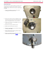
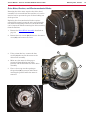
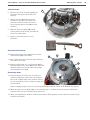
Drive Motor, Brushes, and Electromechanical Brake . . . . . . . . . . . . . . . . . . . . . . . . . . . . . 87
Carbon Brushes . . . . . . . . . . . . . . . . . . . . . . . . . . . . . . . . . . . . . . . . . . . . . . . 88
Drive Tire . . . . . . . . . . . . . . . . . . . . . . . . . . . . . . . . . . . . . . . . . . . . . . . . . . . . . 89
Steering Chain . . . . . . . . . . . . . . . . . . . . . . . . . . . . . . . . . . . . . . . . . . . . . . . . . . 91
Specicaons . . . . . . . . . . . . . . . . . . . . . . . . . . . . . . . . . . . . . . . . . . . . . . . . 92
Special Tools . . . . . . . . . . . . . . . . . . . . . . . . . . . . . . . . . . . . . . . . . . . . . . . . 93
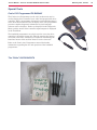
Curs 1311 Programmer PN 56409441 . . . . . . . . . . . . . . . . . . . . . . . . . . . . . . . . . . . . 93
Tire “Puller” Kit PN 56422174 . . . . . . . . . . . . . . . . . . . . . . . . . . . . . . . . . . . . . . . . . 93

General Information 6Service Manual – Focus II / Scrubtec R6 Rider Autoscrubber
General Information
Service Manual Purpose and Application
This Service Manual is a resource for professional service technicians. It provides information for
understanding how the machine operates, where components are located, basic troubleshooting,
maintenance and mechanical service operations.
The cover page of this manual lists each machine part number that the manual applies to. Compare the part
number of the machine you are working on to the model numbers listed on the cover page to be sure you are
using the correct manual.
Revision History
• 11/13
• Electrical System: Updated wiring diagram 56114061 Rev B to Rev C.
• Control System: Explained that Main Machine Controller code 07 can be caused by failing to program
controller after installing a second vacuum motor.
• General Information, General Specications: Added metric values
• Wheel System, Traction, Special Tools: Added Tire Puller Kit part number and photo.
• 07/14
• Control System: Claried programming options for S.P.E charger VS Delta-Q
• Electrical System: Added information for Delta-Q IC650 onboard battery charger and added wiring
diagrams.
Other Reference Manuals and Information Sources
The following documents contain parts information and instructions for machine operation:
• Instructions for Use: OM56091040 through OM56091046
• Parts List: PL56042589 and PL56042590
Conventions
Forward, backward, front, rear, left or right are intended with reference to the operator’s position, that is to
say in operating position with the hands on the handlebar.
Cautions and Warnings
Symbols
It is important for you to read and understand this manual. The information it contains relates to protecting
your safety and preventing problems. The symbols below are used to help you recognize this information.
Danger: Indicates a potentially hazardous situation which, if not avoided, will result in death or
serious injury.
Warning: Indicates a potentially hazardous situation which, if not avoided, could result in death or
serious injury.
Caution: Indicates a potentially hazardous situation which, if not avoided, could result in minor or
moderate injury.
Caution: When used without the Safety Alert Symbol, indicates a potential situation which, if not
avoided, could result in property or machine damage.

General Information 7Service Manual – Focus II / Scrubtec R6 Rider Autoscrubber
General Safety Instructions
Warning!
• This machine should be used only by properly trained and authorized persons.
• Never work under a machine without safety blocks or stands to support the machine.
• Keep sparks, ame and smoking materials away from batteries. Explosive gases are vented
during normal operation.
• Charging the batteries produces highly explosive hydrogen gas. Charge batteries only in well-
ventilated areas away from open ame. Do not smoke while charging the batteries.
• Remove all jewelry when working near electrical components.
• Do not dispense ammable cleaning agents, operate the machine on or near these agents, or
operate in areas where ammable liquids exist.
Caution!:
• When operating this machine, ensure that third parties, particularly children, are not
endangered.
• Turn the key switch off (O) and disconnect the batteries before servicing electrical components.
• Turn the key switch off (O) and remove the key, before changing the brushes, and before
opening any access panels.
• This machine is not suitable for picking up hazardous dust.
• Do not use on surfaces having a gradient exceeding that marked on the machine.
• While on ramps or inclines, avoid sudden stops when loaded. Avoid abrupt sharp turns. Use
low speed down hills. Clean only while ascending (driving up) the ramp.
• Before performing any service function, carefully read all instructions pertaining to that
function.
• Do not leave the machine unattended without rst turning the key switch off (O), removing the
key and securing the machine.
• Take precautions to prevent hair, jewelry, or loose clothing from becoming caught in moving
parts.
• Only use the brushes provided with the appliance or those specied in the instruction manual.
The use of other brushes may impair safety.
• Refer to the battery charger OEM product manual for additional specic battery charger
warnings.
Caution!:
• This machine is not approved for use on public paths or roads.
• Do not use scarier discs or grinding stones. These can damage the machine and the oor
surface.
• Turn the key switch off (O) and remove the key, before changing the brushes, and before
opening any access panels.
• Use caution when moving this machine at or below freezing temperature conditions. Any water
in the solution, recovery or detergent tanks or in the hose lines could freeze, causing damage to
valves and ttings. Flush with windshield washer uid.
• The batteries must be removed from the machine before the machine is scrapped. The disposal
of the batteries should be safely done in accordance with your local environmental regulations.
• Do not clean this machine with a pressure washer.
• All doors and covers are to be positioned as indicated in the instruction manual before using
the machine.

General Information 8Service Manual – Focus II / Scrubtec R6 Rider Autoscrubber
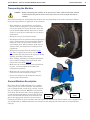
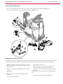
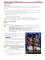
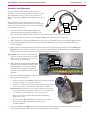
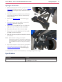
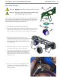
Transporting the Machine
Caution: Before transporting the machine on an open truck or trailer, make sure that the machine
is tied down securely and all access doors and covers are secured (tape and strap as
needed).
The actual procedure for transporting the machine will vary depending on the mode of transport. Follow
these general guidelines as applicable to the situation.
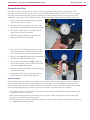
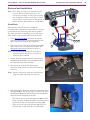
• If the machine is not operational or cannot be
moved under its own power, you must manually
release the brake. To release the brake, move the
release handle (27) outward and insert an object,
such as a screw driver, behind the lever to keep it
deactivated.
• Drain the recovery and solution tanks.
• If transport will occur below freezing temperatures,
place a small amount of environmentally friendly
antifreeze in the recovery tank, solution tank,
and solution lines. After transport, make sure to
dispose of the used antifreeze according to local
regulations.
• Remove the squeegee from the machine (page
74). This is required to access the rear hold
down points and also protects the squeegee during
loading, unloading, and transport.
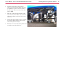
• If the loading, unloading, or transport operations
pose a risk for damage to the scrub deck, then
remove the scrub deck (page 59).
• Make sure the recovery tank is securely fastened
in place, or removed from the machine and
transported separately.
• Make sure the recovery tank cover is securely
held closed or removed from its hinges.
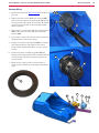
• Secure the machine to the transport using the
anchor points shown below.
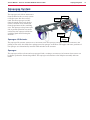
General Machine Description
The Clarke Focus II Rider/Scrubtec 6 is a compact
battery power ride on oor scrubber. The machine
can be equipped with a 28 inch (71 cm) disc, 34 inch
disc, 28 cylindrical, 28 inch BOOST or 38 inch Disc
scrub deck. The machine may also be equipped with
an onboard detergent mixing system. This system
stores concentrated detergent on the machine and
meters the appropriate quantity of concentrated
detergent and mixes it on the machine with water from the solution tank. The machine can be equipped with
wet acid (ooded) or AGM (maintenance free) batteries and charged with either shelf or on board battery
chargers
27
Front Anchor
Points
Rear Anchor
Points

General Information 9Service Manual – Focus II / Scrubtec R6 Rider Autoscrubber
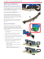
Nameplate
The nameplate contains important
identication information which will be
needed when ordering parts: Model (Name),
Part No. (Part number of the machine which
is often referred to as the “Model Number”),
and Serial Number.
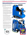
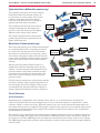
Know Your Machine — Major components:
Recovery
Tank
Squeegee
Subframe
Scrub
Deck
Drive Wheel
and Motor
Steering
Column
Solution
Tank
Operator’s
Seat
Electrical
Panel
Sample

General Information 10Service Manual – Focus II / Scrubtec R6 Rider Autoscrubber
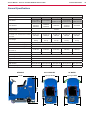
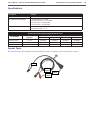
General Specifications
Specifications
Model Category 28” Disc 28” Boost 28” Cyl. 34” Disc 38” Disc
Model Name
Focus II 28 D
Scrubtec R 6 71
Focus II 28 B
Scrubtec R 6 71C
Focus II 34 D
Scrubtec R 6 86 Scrubtec R 6 100
Model Number
56114000
56114010
56114004
56114003
56114009
56114005
56114002
56114001
56114006
56114008
Battery Voltage 24 Volts
Protection Grade IPX3
Sound Pressure Level
IEC 60335-2-72: 2002 Amend. 1:2005,
ISO 11201
68.3dB LpA
3dB KpA
68.6dB LpA
3dB KpA
68.3dB LpA
3dB KpA
68.3dB LpA
3dB KpA
68.3dB LpA
3dB KpA
Gross Weight
1,341 lbs
608 kg
1,371 lbs
622 kg
1,359 lbs
616 kg
1,350 lbs
613 kg
1,603 lbs
727 kg
Maximum Wheel Floor Loading (front)
152 psi (1.05 N/mm
2
)
Maximum Wheel Floor Loading (right rear)
193 psi (1.33 N/mm
2
)
Maximum Wheel Floor Loading (left rear)
154 psi (1.06 N/mm
2
)
Vibrations at the Hand Controls
(ISO 5349-1)
0.181
m/s
2
0.386
m/s
2
0.181 m/s
2
0.181
m/s
2
0.181 m/s
2
Vibrations at the Seat (EN 1032)
0.014
m/s
2
0.132
m/s
2
0.014 m/s
2
0.014
m/s
2
0.014 m/s
2
Gradeability Transport
12.5% (7.1°)
Gradeability Cleaning
7.9% (4.5°)
Height 54.8” (139 cm)
Length 60.5” (154 cm)
Width at Deck 32.1” (82 cm) 32.1” (82 cm) 32.8” (83 cm) 36.6” (93 cm) 42.1” (107 cm)
Width at Squeegee 32.5” (83 cm) 32.5” (83 cm) 32.5” (83 cm) 41.3” (105 cm) 46.3” (118 cm)
Length Squeegee Width Squeegee Width
Deck Width Deck Width
Height
All Models 28” & 34” Models 38” Models

General Information 11Service Manual – Focus II / Scrubtec R6 Rider Autoscrubber
Fastener Torque Specifications
Standard Torque
Specifications (unless
otherwise specified)
Size Plated Steel Stainless Steel
#10 42 in.-lb. 28 in.-lb.
1/4“ 100 in.-lb. 67 in.-lb.
5/16” 17 ft.-lb. 11 ft.-lb.
3/8” 31 ft.-lb. 20 ft.-lb.
1/2” 75 ft.-lb. 50 ft.-lb.
3/4” 270 ft.-lb. 180 ft.-lb.
M5 61 in.-lb. 36 in.-lb.
M6 9 ft.-lb. 62 in.-lb.
M8 22 ft.-lb. 13 ft.-lb.
M10 44 ft.-lb. 25 ft.-lb.
M12 70 ft.-lb. 40 ft.-lb.
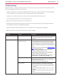
Maintenance Schedule
Maintenance intervals given are for average operating conditions. Machines used in severe operational
environments may require service more often.
Maintenance Item
Interval
Daily Weekly Monthly Yearly
Charge Batteries •
Check/Clean Tanks & Hoses (clean recovery tank switches & vacuum
inlet screen)
•
Check/Clean/Rotate the Brushes/Pads •
Check/Clean the Squeegee •
Clean Hopper on Cylindrical System •
Check Battery Cell Water Level (does not apply to gel cell batteries) •
Inspect Scrub Housing Skirts •
If so equipped, replace the boost deck isolators 250 hours
Inspect and clean Solution Filter •
Clean Solution Manifolds on Cylindrical System •
Purge Detergent System (if present) •
Lubricate the Machine •
Check Vacuum Motor Carbon Brushes 300 hours
Check Brush Motor Carbon Brushes 500 hours
Check Drive Motor Carbon Brushes 500 hours
Note: See the individual machine system sections for maintenance information.
Carbon Brush Notes:
− The original (new) length of each carbon brush is 1” (25.4mm) on brush and wheel drive motors.
− Replace carbon brushes when shorter than 3/8” (10mm) {1/4” (6mm) for drive motor} to obtain
the same motor efciency as new brushes.
− Important: Motor damage resulting from failure to service the carbon brushes is not covered under
warranty. See the Limited Warranty Statement.

General Information 12Service Manual – Focus II / Scrubtec R6 Rider Autoscrubber
Lubricating the Machine
• Once a month, apply light machine oil to lubricate the components marked by (OL) below:
• Once per quarter Grease the components marked by (GR) below.
GR
OL
GR
GR
OL
OL
OL
OL
OL
OL
OL
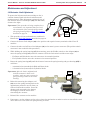
Diagnostic and Service Tools
In addition to a full set of metric and standard tools, the following items are required in order to successfully
and quickly perform troubleshooting and repair of Nilsk-Advance Industrial oor cleaning equipment.
• Laptop computer loaded with current version of
EzParts, Adobe Reader and (preferably cellular)
internet access
• Digital volt ohmmeter (DVOM) with DC current
clamp
• Hydrometer
• Battery load tester for checking 12V and 6V
batteries.
• Static control wrist strap
• Set of torque wrenches
• Hard (printed) copies of service manuals for
regularly serviced machines (available at
www.advance-us.com and other Nilsk-Advance
websites).
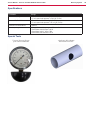
These tools are also available from Nilsk-Advance,
Inc.:
• Vacuum water lift gauge, p/n 56205281

General Information 13Service Manual – Focus II / Scrubtec R6 Rider Autoscrubber
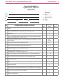
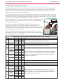
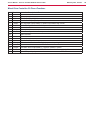
Focus II and Scrubtec R 6
Cylindrical, Disc, and Boost
PM Checklist
Defect Codes
Customer A needs adjustment
B binding
Address C dirty or contaminated
D damaged, bent or torn
City St Zip L leaks
M missing
Model Serial Hours W worn out
Ref
OPERATIONAL INSPECTION ITEMS
OK or
N/A
Defect Codes
(circle)
Does Not
Work
1 Steering A B
2 Drive Pedal Operational (check for Fwd/Rev Drive & any neutral creep) A B D
3 Seat Switch D
4
Electrical Parking Brake (Brake releases when the key is turned on and the drive pedal is
engaged. Brake engages when machine is at rest.)
A B W
5
Drive System Performance (refer to Curtis Programmer Manual SM56043101 for speed
control changes)
Noisy
Sluggish
6 Scrub System (Raise, Lower, auto scrubbing functions) A B
7 Scrub Brush (pressure settings Normal/Heavy/Extreme scrub) A B
8 Squeegee System (Raise, Lower, Auto-raise in reverse) A B D
9a
Vacuum Performance Single Motor
(sealed water lift 63”, 1-inch open hole aperture 10”)
C L W
9b Vacuum Performance Dual Motor (sealed water lift 65”, 1-inch open hole aperture 18”) C L W
10 Solution Control (On/Off, Increase & Decrease for Normal/Heavy/Extreme) A B L
11 Emergency Stop Knob B D
12 Seat A B D
13 Optional Accessories D
14
Main Control Board Special Program Options and Fault Recall Mode– check all applicable
program settings per Changing Program Settings section and examine stored fault codes.
15 Battery Charger Programmed Correctly for Battery A
16 Battery Charger Operation D

General Information 14Service Manual – Focus II / Scrubtec R6 Rider Autoscrubber
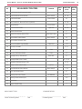
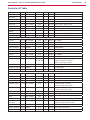
Ref
VISUAL INSPECTION ITEMS
Comments
OK or
N/A
Defect Codes
(circle)
Does Not
Work
17 Scrub Brushes (check for wear and rotate) A B D W
18 Scrub Brush Motor Carbon Brushes Wear Limit 3/8” B L W
19 Scrub Brush Gimbals In Brush Plates W
20 Auto Tension Belt – Wear and Tension (cylindrical) A D W
21 Spring Retainers In Brush Plates D
22 Scrub Deck Skirt Position Slight Flare A B W
23 Solution Solenoid Valve C L
24 Solution Tank, Delivery Hoses & Filter Clean Filter Screen C L
25 Vacuum Motor Carbon Brushes Wear Limit 3/8” W
26 Vacuum Motor Gaskets & Filters L W
27 Vacuum Float Ball & Cage Assembly Clean Float C M
28 Recovery Lid Gasket C D L
29 Recovery Tank Drain Hose & Cap Flush C L
30 Recovery Tank Strainer Basket Clean C D
31 Squeegee Pick-Up Tool and Hose Back Flush C L
32 Squeegee Blades (clean & rotate) A C D W
33 Squeegee Lift Actuator Motor & Cable A B D
34 Battery Condition (clean & water) Load Test C W
35 Drive Wheel Motor Carbon Brushes Wear Limit 1/4” C W
36 Drive Pedal Neutral Return A C
37 Steering Chain Lube & Tension 1/4” Deection A B C
38 Steering Column Universal Joint A D
39 Rear Wheels C
40 Hopper (Cylindrical only C
WORK COMPLETED BY: ACKNOWLEDGED BY:
__________________________________ _________ ________________________________ ________
Service Technician Signature Date Customer Signature Date

Chassis System 15Service Manual – Focus II / Scrubtec R6 Rider Autoscrubber
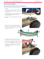
Chassis System
Functional Description
The chassis system consists of a tubular frame that provides the main substructure for the rest of the
machine. To support the concentrated weight of the batteries, the battery box rests directly on the chassis.
The solution tank bolts to the chassis to support the tank and make it more rigid.
The forward drive wheel is connect to the frame through a thrust bearing block for rotational movement. An
integral (welded) rear axle through the frame transfers the load of the machine to the rear idler (non-driven)
wheels.
The scrub deck lift actuator and linkages mounts to the underside of the frame. This assembly is not
normally removed from the system during maintenance. Similarly, the squeegee lift mechanism mounts
directly to the underside of the frame via ball joints that permit vertical and lateral movement.
Squeegee
Chassis
Scrub
Deck
Drive Wheel
and Motor

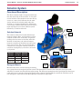
Control System 16Service Manual – Focus II / Scrubtec R6 Rider Autoscrubber
Control System
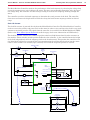
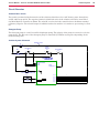
Functional Description
Within the Focus system there are two primary controllers: the Main Machine Controller (A1) and the
Wheel Drive controller (A2). The Main Machine Controller controls the primary machine functions, and the
Wheel controller controls the drive functions. The Wheel controller communicates with the Main Machine
Controller to inform the Main Machine Controller of machine movement status.
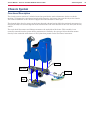
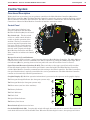
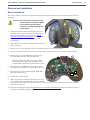
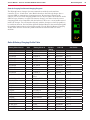
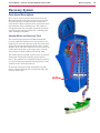
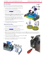
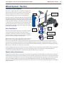
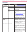
Control Panel
The control panel (display) is an
integral component with the Main
Machine Controller (A1) circuit board.
Key Switch (A): The key switch
serves as a main control switch to
enable or disable operation of the
machine. The key is removable to
prevent unwanted operation when
not in use. The key switch doesn’t
disconnect any power circuits, but
instead, sends a signal to both the
Main Machine Controller and Wheel
Drive controller to indicate the On/Off
function.
Reverse Switch (C) and Indicator
(B): The reverse switch activates a toggle function within the Main Machine Controller. The Main Machine
Controller then sends a reverse command to the Wheel controller by pulling the (J3-3) output high. When
the Indicator (B) is lit, pressing down on the foot pedal will cause the machine to move in reverse.
Speed Increase/Decrease Switches (D & E): These switches set the upper speed limit of the machine
for the full throttle position. The machine speed limit is controlled within the Main Machine Controller,
and the Main Machine Controller communicates this setting to the Wheel controller. For Wheel controllers,
the speed limit function is typically controlled with a 3-wire potentiometer. The Main Machine Controller
contains an electronically controlled potentiometer.
Graphic Display (F): Machine operation information is presented to the operator on the graphic display.
F1: Detergent Strength Indicator (for detergent systems only).
F2: Detergent Ratio (for detergent systems only).
F3: Hour meter (total use of the machine)
F4: Battery Indicator
F5: Fault Indicator
F6: Fault Code
F7: Speed Limit Indicator
F9: Battery Low Screen
Horn Switch (G): Activates the horn
Scrub On/Off Switch (M): Pressing this switch will toggle the scrub system on and off. When active, the
scrub deck will lower for the Deck Down Time. When the machine begins to move, the squeegee will lower
G
E
D
C
B
A
H
J
K
L
M
N
O
Q
P
R
S
F
!
F1
F2
F7
F3
F4
F5
F9
F6

Control System 17Service Manual – Focus II / Scrubtec R6 Rider Autoscrubber
and the solution and vacuum systems will turn on. The brushes will turn on and the scrub deck will continue
to lower until the expected motor amperage is reached.
Brush Pressure Increase and Decrease Switches (H & K): When scrub mode is active, pressing these
switches will increase or decrease the scrub brush pressure. The three indicator LEDs (H) will illuminate to
represent High, Medium, and Low pressure settings.
Solution Switch (O): The solution system will be active when the Scrub On/Off system is engaged.
Pressing this switch will cycle through the solution rates (Normal, Medium, High, and Off). The solution
ow will turn on only when the machine is in forward transport. The solution ow will turn off if the throttle
returns to neutral or reverse transport is active. Pressing this switch when the scrub system is off will
momentarily turn the solution ow on to allow pre-wetting of the scrub brushes.
Vacuum Switch (Q): The vacuum system will be automatically active when the Scrub system is active.
This switch is used to toggle the vacuum system on or off independent of whether the scrub system is active
or not.
Detergent Switch (R): The detergent injection system is an optional accessory. The detergent pump is
active only when the solution pump is active. Pressing this switch will cycle through the detergent ratios.
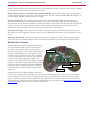
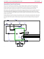
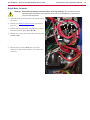
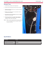
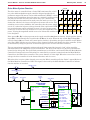
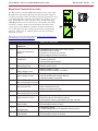
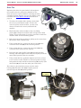
Main Machine Controller
The Main Machine Controller (A1), which includes
the control board and the display, is the primary
electronic control for the Focus machine and its
functions (except drive control). The control board is
the basic input/output device and contains a micro-
controller chip to regulate function. The controller
receives and interprets user inputs, sensor inputs,
and even some motor amperage readings, and
controls device output for the user display, solenoid
operation, and motor control. Most low and medium
power outputs are controlled with power MOSFET
transistors, and very high power devices (vacuum
and brush motors) controlled with external motor
contactors.
Another function of the Main Machine controller is
to detect any system failures and display an error code on the display panel or store it in the main control
board’s memory. The error code(s) are used to help the service person determine the fault and to quickly
guide in repairing a specic system malfunction. An additional special feature of the main control board is
to change program settings for a set of specic machine functions. See the section,Main Machine Controller
Programming described on page 19 for further information.
J1 Connector
J2 Connector
Key Switch
J3 Connector

Control System 18Service Manual – Focus II / Scrubtec R6 Rider Autoscrubber
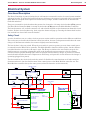
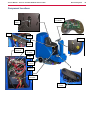
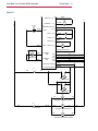
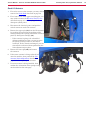
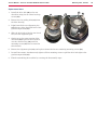
Component Locations
Vacuum
Contactor
Brush
Contactor
Wheel Drive
Controller
150 Amp
Fuse
Battery Pos.
Terminal
Battery Neg.
Terminal
70 Amp
Breaker
10 Amp
Breaker
E-Stop
Seat
Switch
Main Machine
Controller
Drive Pedal
Sensor
Key Switch

Control System 19Service Manual – Focus II / Scrubtec R6 Rider Autoscrubber
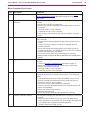
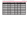
Main Machine Controller Programming
The Main Machine Controller is programmable for machine specic functions and parameters through a
hidden menu system. This is a required task when replacing the controller with a new controller or changing
features. The listings below and following sections describe the parameters to be programmed. Refer to
Navigating the Hidden Menus on page 20.
Programming Menu Outline
1. Deck Type
• 28 Inch Boost
• 40 Inch Disc
• 34 Inch Disc / BR855
• 28 Inch Cyl / BR755C
• 28 Inch Disc / BR755
2. Battery Charger
• AGM Fullriver 25A †
• Wet 15A
• Gel-AGM 25A
• Gel Exide 25A
• AGM Discover 25A
• Wet 25A
• None
3. Chemical Selection
• Onboard Chemical
• No Onboard Chemical
4. Detergent Mode
• 1. Off
5. Vacuum Selection
• 2 Vacuum Motors
• 1 Vacuum Motor
6. Low Voltage Cutout
• Main Free Battery 70%
LVC = 21.75V
• Wet Battery 80%
LVC = 20.55V
7. Max Scrub Speed
• 100% of Transport
8. Lockout Brush Pre (Pressure)
• 1. None
9. Lockout Sol Flows (Solution)
• 1. None
10. Recovery Tank Full
• 1. Disabled
11. Chemical Rate Bias
• 1. None
12. Deck Down Time
• x.x Seconds
(1.0 to 5.0 in 0.1 increment)
13. Restore Defaults
• 2. Yes
• 1. No
14. Display Rev Level
• Rev xx
15. Fault Recall
• -- (none)
16. Fault Detection
• 1. Enabled
• 2. Disabled
17. Service Test Mode
• See Service Test Mode on
page 22
18. Backup Alarm Vol (Volume)
• 4. High
• 3. Medium
• 2. Low
• 1. Off
19. FWD Alarm Vol (Forward)
• 4. High
• 3. Medium
• 2. Low
• 1. Off
20. Horn Volume
• 4. High
• 3. Medium
• 2. Low
• 1. Off
21. Panel Test
† For North and South American (Clark) models equipped with Fullriver brand batteries only. Selecting this
option on a Nilsk-Alto model charger will result in that charger to operate with a “Gel-AGM-15A” mode.

Control System 20Service Manual – Focus II / Scrubtec R6 Rider Autoscrubber
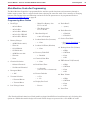
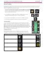
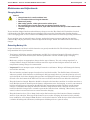
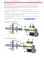
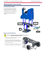
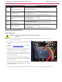
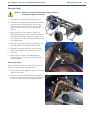
Navigating the Hidden Menus
To enter the hidden menus, press and hold the Scrub (M) and Vacuum
(Q) switches for 2 seconds while turning the key switch (A) to the On
position. After 2 seconds, the display will show the rst menu item,
“1. Deck Type”, and you can release the switches.
M
Q
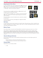
Use the Speed Increase (E) or Speed Decrease (D) switches to scroll
through the menus and submenu options.
E
D
Use the Solution switch (O) to enter a submenu. Use the Scrub switch
(M) to exit a submenu. The submenu option displayed on-exit will be
saved to memory.
To save the changes and exit the hidden menus, turn the key switch to
the off position.
To abort changes, turn the key switch (A) to the off position without
exiting the submenu.
O
M
Deck Type
To ensure proper operation of the motor(s), the controller needs to know what type of deck is installed on the
machine. The options are: 28” Boost, 40” Disk, 34” Disc, 28” Cyl., 28” Disc. This parameter must be set when
replacing the Main Machine Controller.
Battery Charger
If no onboard charger is present or the Delta-Q IC650 is installed, this parameter must be set to “None”.
If the machine is equipped with the optional S.P.E onboard battery charger, then the controller needs
to know the type of batteries installed in the machine. This information is communicated from the Main
Machine controller to the S.P.E battery charger, so that it uses the correct charging prole for the batteries.
If the installed batteries are rated for 150 amp-hour (or less) discharge, then a 15-amp charging rate must be
selected.
Chemical (Detergent) Selection
The detergent selection menu is used to disable the detergent system or to set the display type for the
detergent ratio.
• Onboard Chemical, activates the onboard detergent system.
• No Onboard Chemical, disables the onboard detergent system.
Detergent Mode
This function is not currently available.
• 1. Off
Page is loading ...
Page is loading ...
Page is loading ...
Page is loading ...
Page is loading ...
Page is loading ...
Page is loading ...
Page is loading ...
Page is loading ...
Page is loading ...
Page is loading ...
Page is loading ...
Page is loading ...
Page is loading ...
Page is loading ...
Page is loading ...
Page is loading ...
Page is loading ...
Page is loading ...
Page is loading ...
Page is loading ...
Page is loading ...
Page is loading ...
Page is loading ...
Page is loading ...
Page is loading ...
Page is loading ...
Page is loading ...
Page is loading ...
Page is loading ...
Page is loading ...
Page is loading ...
Page is loading ...
Page is loading ...
Page is loading ...
Page is loading ...
Page is loading ...
Page is loading ...
Page is loading ...
Page is loading ...
Page is loading ...
Page is loading ...
Page is loading ...
Page is loading ...
Page is loading ...
Page is loading ...
Page is loading ...
Page is loading ...
Page is loading ...
Page is loading ...
Page is loading ...
Page is loading ...
Page is loading ...
Page is loading ...
Page is loading ...
Page is loading ...
Page is loading ...
Page is loading ...
Page is loading ...
Page is loading ...
Page is loading ...
Page is loading ...
Page is loading ...
Page is loading ...
Page is loading ...
Page is loading ...
Page is loading ...
Page is loading ...
Page is loading ...
Page is loading ...
Page is loading ...
Page is loading ...
Page is loading ...
-
 1
1
-
 2
2
-
 3
3
-
 4
4
-
 5
5
-
 6
6
-
 7
7
-
 8
8
-
 9
9
-
 10
10
-
 11
11
-
 12
12
-
 13
13
-
 14
14
-
 15
15
-
 16
16
-
 17
17
-
 18
18
-
 19
19
-
 20
20
-
 21
21
-
 22
22
-
 23
23
-
 24
24
-
 25
25
-
 26
26
-
 27
27
-
 28
28
-
 29
29
-
 30
30
-
 31
31
-
 32
32
-
 33
33
-
 34
34
-
 35
35
-
 36
36
-
 37
37
-
 38
38
-
 39
39
-
 40
40
-
 41
41
-
 42
42
-
 43
43
-
 44
44
-
 45
45
-
 46
46
-
 47
47
-
 48
48
-
 49
49
-
 50
50
-
 51
51
-
 52
52
-
 53
53
-
 54
54
-
 55
55
-
 56
56
-
 57
57
-
 58
58
-
 59
59
-
 60
60
-
 61
61
-
 62
62
-
 63
63
-
 64
64
-
 65
65
-
 66
66
-
 67
67
-
 68
68
-
 69
69
-
 70
70
-
 71
71
-
 72
72
-
 73
73
-
 74
74
-
 75
75
-
 76
76
-
 77
77
-
 78
78
-
 79
79
-
 80
80
-
 81
81
-
 82
82
-
 83
83
-
 84
84
-
 85
85
-
 86
86
-
 87
87
-
 88
88
-
 89
89
-
 90
90
-
 91
91
-
 92
92
-
 93
93


Nilfisk-ALTO Scrubtec R 6-71 28D User manual
- Category
- Scrubber
- Type
- User manual
- This manual is also suitable for
Ask a question and I''ll find the answer in the document
Finding information in a document is now easier with AI
Related papers
-
Nilfisk-ALTO SCRUBTEC R 466 User manual
-
-
-
Alto 586 User manual
-
-
-
-
-
-
Other documents
-
Viper 50000398 Quick start guide
-
SportsArt 5002 Owner's manual
-
Powr-Flite PAS26R Owner's manual
-
Viper AS4335C Use And Maintenance
-
Windsor SGJ32 User manual
-
Viper AS7690T Use And Maintenance
-
Dustbane Hurricane Scooter Ride-On Operating instructions
-
Windsor SCEX364 User manual
-
Nilfisk-Advance 56397013 User manual
-
SPT 10139 Operating instructions