Page is loading ...

Table of Contents Rev. 11/27/2018 MPU-DC GEN2, MANUAL
Table of Contents Copyright 2018 Vestil Manufacturing Co. Page 1 of 23
MPU-DC GEN2 Battery-Powered Modular Power Unit
Instruction Manual
Receiving instructions:
After delivery, remove the packaging from the product. Inspect the product closely to determine whether
it sustained damage during transport. If damage is discovered, record a complete description of it on the
bill of lading. If the product is undamaged, discard the packaging.
NOTE:
The end-user is solely responsible for confirming that product design, use, and maintenance comply with
laws, regulations, codes, and mandatory standards applied where the product is used.
Replacement Parts and Technical Assistance:
For answers to questions not addressed in these instructions and to order replacement parts, labels,
and accessories, call our Technical Service and Parts Department at (260) 665-7586. The department can
also be contacted online at http://www.vestilmfg.com/parts_info.htm.
Vestil Manufacturing Corp.
2999 North Wayne Street, P.O. Box 507, Angola, IN 46703
Telephone: (260) 665-7586 -or- Toll Free (800) 348-0868
Fax: (260) 665-1339
Web: www.vestilmfg.com e-mail: info@vestil.com
Table of Contents
Signal Words….………………………………………………………………………………………………………………………….....2
Hazards of Improper Use…..………………………..…………………………………..………………………………………..………2
Notes……………………………………………………………………………………………………………..……………...................3
MPU Harness Wiring Diagram…………………………………………………………………………………………………….………3
12V DC Circuit Diagram: Upper Travel Limit Switch; No Toeguard..…………...........................................................................4
12V DC Circuit Diagram: Upper Travel Limit Switch + Toeguard……………………………………………………….……………5
12V DC Power Unit Assembly Exploded View and Bill of Materials………………………………………………….……..……..6, 7
24V DC Power Unit Assembly Exploded View and Bill of Materials……………………………………………….………………8, 9
12V DC Power Unit Assembly without Pushbuttons Exploded View and Bill of Materials………………….……….………..10, 11
24V DC Power Unit Assembly without Pushbuttons Exploded View and Bill of Materials…………………………….……..12, 13
12V DC Power Unit Subassembly Exploded View and Bill of Materials…………………………………………………………….14
24V DC Power Unit Subassembly Exploded View and Bill of Materials…………………………………………………………….15
Detail View A: Motor + Pump Subassembly, 12V, 1.14HP…………………………………………………………………………..16
Detail View B: Motor + Pump Subassembly, 12V, 2.15HP…………………………………………………………………………..16
Detail View C: Motor + Pump Subassembly, 24V, 2.15HP…………………………………………………………………………..16
Detail View D: Manifold Subassembly, 24V……………………………………………………………………………………………17
Detail View E: Manifold Subassembly, 12V……………………………………………………………………………………………17
Hydraulic Circuit Diagram……………………………………………………………………………………………………….……….18
Power Unit Operation…………………….…………………………………………………………………………………………..18-19
Removing the cover……………………………………………………………………………………………………………………….19
Cleaning the Lowering Solenoid Valve……………………………………………………………………………………………........19
Bleeding Air from Hydraulic System…………………………………………………………………………………………………….20
Recharging the Battery…………………………………………………………………………………………..…………………….…20
Inspections and Maintenance……………………………………………………………………………………………………..…20-21
Labeling Diagram……...…………………………………………………………………………………………………………….........21
Troubleshooting…………………………………………………………………………………………………………………….....21-22
Limited Warranty…...……………………………………………………………………………………………………………………...
23

Table of Contents Rev. 11/27/2018 MPU-DC GEN2, MANUAL
Table of Contents Copyright 2018 Vestil Manufacturing Co. Page 2 of 23
SIGNAL WORDS
This manual uses SIGNAL WORDS to indicate the likelihood of personal injuries, as well as the probable
seriousness of those injuries, if the product is misused in the ways described. Other signal words call attention to
uses of the product likely cause property damage. The signal words used appear below along with the meaning of
each word:
Identifies a hazardous situation which, if not avoided, WILL result in DEATH or SERIOUS
INJURY. Use of this signal word is limited to the most extreme situations.
Identifies a hazardous situation which, if not avoided, COULD result in DEATH or SERIOUS
INJURY.
Indicates a hazardous situation which, if not avoided, COULD result in MINOR or MODERATE
injury.
Identifies practices likely to result in product/property damage, such as operation that might
damage the product.
Hazards of Improper Use:
We strive to identify foreseeable hazards associated with the use of our products, but no manual can address
every risk. The most effective means for avoiding injury is to exercise sound judgment whenever using this
device.
Improper or careless operation might result in serious personal injuries.
• Read and understand the entire manual before assembling, using or servicing the power unit. Read the
manual to refresh your understanding of proper use and maintenance procedures as necessary.
• DO NOT work on a battery UNLESS you are wearing personal protective equipment, particularly a face shield.
Batteries contain sulfuric acid and produce explosive gases. A battery explosion could result in loss of eyesight
and/or serious burns.
• DO NOT smoke near the battery or expose the battery to sparks or flames.
• Charge batteries ONLY in clean, dry, and well-ventilated locations.
• DO NOT touch the battery terminals. Remove personal items like rings and watches BEFORE beginning to
work on the battery. The battery can produce energy sufficient to weld jewelry to metal; underlying skin could be
severely burned.
• Keep fresh water and soap nearby in case battery acid contacts skin, clothing, or eyes. Immediately rinse any
skin that has been contacted by acid. If acid gets in your eyes, rinse them thoroughly with eye wash. After
rinsing the affected area, notify your supervisor about the incident.
• Replace damaged cables and wiring as soon as the damage is discovered.
• Check the water level in the battery at least once per month.
• Operating the power unit when battery voltage is low can cause premature motor contactor failure.
• DO NOT perform maintenance on this power unit UNLESS it is unloaded. Refer to the “Inspections &
Maintenance” section of your product owner’s manual (i.e. the manual for your cart, table, lift, etc.). Put the
product into the recommended maintenance configuration. If repairs are necessary, ONLY install manufacturer-
approved replacement parts.
•
DO NOT use the power unit unless it is in normal condition. See Inspections & Maintenance on p. 20.
• Watch the cylinder while extending and retracting the piston. It should move smoothly. Watch for binding or
jerky movement and listen for unusual noises. Tag the unit "Out of order" and do not use it if you observe
anything abnormal.
• DO NOT continue to press the UP button if the piston is fully extended.
•
DO NOT use the power unit UNLESS all labels are in place and readable. See Labeling diagram on p. 21.
• DO NOT modify this power unit in any way. Modifications automatically void the limited warranty and might
make the unit unsafe to use.
Proper use and maintenance are essential for this product to function properly.
• Periodically lubricate moving parts.
• Keep the product clean & dry.
• Only use approved replacement parts. To order replacement or spare parts for this equipment, contact the
factory.


Table of Contents Rev. 11/27/2018 MPU-DC GEN2, MANUAL
Table of Contents Copyright 2018 Vestil Manufacturing Co. Page 6 of 23
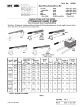
12V POWER UNIT ASSEMBLY: 12V DC, 1-PHASE, 1.14HP OR 2.15HP MOTOR,
99-660-(001-024)-MANUALS DASHBOARD WITH 2-PUSHBUTTONS
USER SELECTED PUMP DISPLACEMENT AND FLOW CONTROL
L-H-L HYDRAULIC CIRCUIT
1.5 GALLON HORIZONTAL TANK
See MPU
Harness Wiring
Diagram
on p. 3

Table of Contents Rev. 11/27/2018 MPU-DC GEN2, MANUAL
Table of Contents Copyright 2018 Vestil Manufacturing Co. Page 7 of 23
Item Part no. Description Qty. Item Part no. Description Qty.
1 99-514-021
FRAME, MPU GEN2 1 15 99-533-024
ASSEMBLY, 18/7, 6-PIN, MATE-
N-LOCK X 24”
1
2 99-016-076
BRACKET, CLAMP PLATE,
BACK CONNECTION
1 16 99-533-057
ASSEMBLY, WIRE, STRAIGHT,
18/1, 6
1
/
2
” WITH RING
TERMINAL AND FEMALE SPADE
1
3 99-024-036
COVER, POWER UNIT, DC,
GEN II
1 17 99-533-060
ASSEMBLY,WIRE, STRAIGHT, 4/1,
WELD WIRE, 4’ RED, DOUBLE
RING TERMINAL
1
4 99-033-024
CORD CHARGER 1 18 99-642-001
FUSE HOLDER FOR ANL
ASSEMBLY
1
5 99-034-013
STRAP, BATTERY BOX, WITH
BUCKLE
1 19 01-034-001
ACCESSORIES, ELECTRICAL,
WIRE NUT, GRAY 2-22GA TO
2-16GA
2
6 99-034-084
ELECTRICAL CORD CLAMP
PLATE
1 20 15-533-012
ASSEMBLY, WIRE, STRAIGHT, 4/1
WELD WIRE, 12’ BLACK,
DOUBLE RING TERMINAL
1
7 99-139-003
BATTERY, WET, LEAD-ACID,
GROUP 24, DEEP CYCLE
1 21 21-034-008
ACCESSORIES, ELECTRICAL
CHARGER, 12V, 5A
1
8 99-145-142
LOCKING PIN WITH RING,
3
/
16
DIAMETER X 1
1
/
4
EFFECTIVE
LENGTH
2 22 11103
HEX BOLT, GRADE A, ZINC
PLATED,
3
/
8
”-16x
3
/
4
”
2
9 99-160-099
POWER UNIT, SUBASSEMBLY,
DC, GEN II MPU DASHBOARD,
2-BUTTON, PBE
1 23 11033
HEX BOLT, GRADE A, ZINC
PLATED,
1
/
4
”-20x
3
/
4
”
4
10
POWER UNIT SUBASSEMBLY: 12V DC, 1-PHASE, 1.14HP,
1800RPM MOTOR; L-H-L CIRCUIT; 1.5 GAL. HORIZONTAL
TANK & FITTINGS; PLUS 1 OF THE FOLLOWING PUMP + FLOW
CONTROL COMBINATIONS
(SEE “POWER UNIT SUBASSEMBLY” ON P. 14)
10
POWER UNIT SUBASSEMBLY: 12V DC, 1-PHASE, 2.15HP,
1800RPM MOTOR; L-H-L CIRCUIT; 1.5 GAL. HORIZONTAL
TANK & FITTINGS; PLUS 1 OF THE FOLLOWING PUMP + FLOW
CONTROL COMBINATIONS
(SEE “POWER UNIT SUBASSEMBLY” ON P. 14)
99-160-137
99-160-138
99-160-139
99-160-140
99-160-141
99-160-142
99-160-143
99-160-144
99-160-145
99-160-146
99-160-147
99-160-148
0.035 DISPLACEMENT PUMP:
0.5GPM FLOW CONTROL
1.0GPM FLOW CONTROL
1.5GPM FLOW CONTROL
2.0GPM FLOW CONTROL
0.060 DISPLACEMENT PUMP:
0.5GPM FLOW CONTROL
1.0GPM FLOW CONTROL
1.5GPM FLOW CONTROL
2.0GPM FLOW CONTROL
0.073 DISPLACEMENT PUMP:
0.5GPM FLOW CONTROL
1.0GPM FLOW CONTROL
1.5GPM FLOW CONTROL
2.0GPM FLOW CONTROL
1
1
1
1
1
1
1
1
1
1
1
1
99-160-149
99-160-150
99-160-151
99-160-152
99-160-153
99-160-154
99-160-155
99-160-156
99-160-157
99-160-158
99-160-159
99-160-160
0.035 DISPLACEMENT PUMP:
0.5GPM FLOW CONTROL
1.0GPM FLOW CONTROL
1.5GPM FLOW CONTROL
2.0GPM FLOW CONTROL
0.060 DISLACEMENT PUMP:
0.5GPM FLOW CONTROL
1.0GPM FLOW CONTROL
1.5GPM FLOW CONTROL
2.0GPM FLOW CONTROL
0.073 DISPLACEMENT PUMP:
0.5GPM FLOW CONTROL
1.0GPM FLOW CONTROL
1.5GPM FLOW CONTROL
2.0GPM FLOW CONTROL
1
1
1
1
1
1
1
1
1
1
1
1
11 99-533-017
ASSEMBLY, CORD, STRAIGHT,
18/5, 30” MOLDED FEMALE
RECEPTACLE, 5-PIN
1 24 33008
FLAT WASHER, LOW CARBON,
USS, ZINC PLATED,
3
/
8
”
2
12 99-533-020
ASSEMBLY, WIRE HARNESS.
MAIN
1
25
33618
MEDIUM SPLIT LOCK WASHER,
1
/
4
”
4
13 99-533-021
ASSEMBLY, 3-PIN, MATE-N-
LOCK, TO DIN COIL
CONNECTOR
1
26 33622
SPLIT LOCK WASHER, CARBON
STEEL, MEDIUM ZINC FINISH,
3
/
8
”
2
27 36102
HEX NUT, GRADE A, ZINC
PLATED,
1
/
4
”-20
4
14 99-533-023
ASSEMBLY, 18/4, 4-PIN, MATE-N-
LOCK
1 28 H-9x450 TIE STRAP, BLACK 2
12V, 2-PUSHBUTTONS POWER UNIT ASSEMBLY BILL OF MATERIALS

Table of Contents Rev. 11/27/2018 MPU-DC GEN2, MANUAL
Table of Contents Copyright 2018 Vestil Manufacturing Co. Page 8 of 23
24V POWER UNIT ASSEMBLY: 24V DC, SINGLE PHASE, 2.15HP, 1800ROM MOTOR,
99-660-(025-036)-MANUALS DASHBOARD WITH 2-PUSHBUTTONS
USER SELECTED PUMP DISPLACEMENT AND FLOW CONTROL
L-H-L HYDRAULIC CIRCUIT
1.5 GALLON HORIZONTAL TANK
See MPU
Harness Wiring
Diagram
on p. 3

Table of Contents Rev. 11/27/2018 MPU-DC GEN2, MANUAL
Table of Contents Copyright 2018 Vestil Manufacturing Co. Page 9 of 23
Item Part no. Description Qty. Item Part no. Description Qty.
1 99-514-021
FRAME, MPU GEN2 1
14 99-533-023
ASSEMBLY, 18/4, 4-PIN, MATE-N-
LOCK
1
2 99-016-076
BRACKET, CLAMP PLATE,
BACK CONNECTION
1 15 99-533-024
ASSEMBLY, 18/7, 6-PIN, MATE-
N-LOCK X 24”
1
3 99-024-036
COVER, POWER UNIT, DC,
GEN II
1 16 99-533-057
ASSEMBLY, WIRE, STRAIGHT,
18/1, 6
1
/
2
” WITH RING
TERMINAL AND FEMALE SPADE
1
4 99-033-024
CORD CHARGER 1 17 99-533-060
ASSEMBLY,WIRE, STRAIGHT, 4/1,
WELD WIRE, 4’ RED, DOUBLE
RING TERMINAL
1
5 99-034-013
STRAP, BATTERY BOX, WITH
BUCKLE
2 18 99-642-003
FUSE HOLDER FOR ANL
ASSEMBLY, w/ 100A ANL
1
6 99-034-084
ELECTRICAL CORD CLAMP
PLATE
1 19 01-034-001
ACCESSORIES, ELECTRICAL,
WIRE NUT, GRAY 2-22GA TO
2-16GA
2
7 21-139-002
BATTERY, 12V DC 2 20 15-533-012
ASSEMBLY, WIRE, STRAIGHT, 4/1
WELD WIRE, 12’ BLACK,
DOUBLE RING TERMINAL
1
8 99-145-142
LOCKING PIN WITH RING,
3
/
16
DIAMETER X 1
1
/
4
EFFECTIVE
LENGTH
2 21 21-034-010
ACCESSORIES, ELECTRICAL
CHARGER, 24V
1
9 99-160-099
POWER UNIT, SUBASSEMBLY,
DC, GEN II MPU DASHBOARD,
2-BUTTON, PBE
1 22 11103
HEX BOLT, GRADE A, ZINC
PLATED,
3
/
8
”-16x
3
/
4
”
2
10
POWER UNIT SUBASSEMBLY: 24V DC, 1-PHASE, 2.15HP,
1800RPM MOTOR; L-H-L CIRCUIT; 1.5 GAL. HORIZONTAL
TANK & FITTINGS; PLUS 1 OF THE FOLLOWING PUMP + FLOW
CONTROL COMBINATIONS
(SEE “POWER UNIT SUBASSEMBLY” ON P. 15)
23 11033
HEX BOLT, GRADE A, ZINC
PLATED,
1
/
4
”-20x
3
/
4
”
4
99-160-161
99-160-162
99-160-163
99-160-164
99-160-165
99-160-166
99-160-167
99-160-168
99-160-169
99-160-170
99-160-171
99-160-172
0.035 DISPLACEMENT PUMP:
0.5GPM FLOW CONTROL
1.0GPM FLOW CONTROL
1.5GPM FLOW CONTROL
2.0GPM FLOW CONTROL
0.060 DISPLACEMENT PUMP:
0.5GPM FLOW CONTROL
1.0GPM FLOW CONTROL
1.5GPM FLOW CONTROL
2.0GPM FLOW CONTROL
0.073 DISPLACEMENT PUMP:
0.5GPM FLOW CONTROL
1.0GPM FLOW CONTROL
1.5GPM FLOW CONTROL
2.0GPM FLOW CONTROL
1
1
1
1
1
1
1
1
1
1
1
1
24 33008
FLAT WASHER, LOW CARBON,
USS, ZINC PLATED,
3
/
8
”
2
25
33618 MEDIUM SPLIT LOCK WASHER,
1
/
4
”
4
26
33622
SPLIT LOCK WASHER, CARBON
STEEL, MEDIUM ZINC FINISH,
3
/
8
”
2
27
36102
HEX NUT, GRADE A, ZINC PLATED,
1
/
4
”-20
4
28
H-9x450 TIE STRAP, BLACK
2
11 99-533-017
ASSEMBLY, CORD, STRAIGHT,
18/5, 30” MOLDED FEMALE
RECEPTACLE, 5-PIN
1
29
99-533-061
ASSEMBLY, WIRE, STAIGHT, 10/1,
9’ W/ DOUBLE RING TERMINAL
1
12 99-533-020
ASSEMBLY, WIRE HARNESS.
MAIN
1
30
99-035-003
ANGLE, STIFFENER, PLASTIC,
FORMED, MPU BATTERY 24V
1
13 99-533-021
ASSEMBLY, 3-PIN, MATE-N-
LOCK, TO DIN COIL
CONNECTOR
1
24V, 2-PUSHBUTTONS POWER UNIT ASSEMBLY BILL OF MATERIALS

Table of Contents Rev. 11/27/2018 MPU-DC GEN2, MANUAL
Table of Contents Copyright 2018 Vestil Manufacturing Co. Page 10 of 23
12V POWER UNIT ASSEMBLY: 12V DC, 1-PHASE, 1.14HP OR 2.15HP, 1800RPM MOTOR
99-660-(037-060)-MANUALS DASHBOARD WITHOUT PUSHBUTTONS
USER SELECTED PUMP DISPLACEMENT AND FLOW CONTROL
L-H-L HYDRAULIC CIRCUIT
1.5 GALLON HORIZONTAL TANK
See MPU Harness
Wiring Diagram on p. 3

Table of Contents Rev. 11/27/2018 MPU-DC GEN2, MANUAL
Table of Contents Copyright 2018 Vestil Manufacturing Co. Page 11 of 23
Item Part no. Description Qty. Item Part no. Description Qty.
1 99-514-021
FRAME, MPU GEN2 1 15 99-533-024
ASSEMBLY, 18/7, 6-PIN, MATE-
N-LOCK X 24”
1
2 99-016-076
BRACKET, CLAMP PLATE,
BACK CONNECTION
1 16 99-533-057
ASSEMBLY, WIRE, STRAIGHT,
18/1, 6
1
/
2
” WITH RING
TERMINAL AND FEMALE SPADE
1
3 99-024-036
COVER, POWER UNIT, DC,
GEN II
1 17 99-533-060
ASSEMBLY,WIRE, STRAIGHT, 4/1,
WELD WIRE, 4’ RED, DOUBLE
RING TERMINAL
1
4 99-033-024
CORD CHARGER 1 18 99-642-001
FUSE HOLDER FOR ANL
ASSEMBLY
1
5 99-034-013
STRAP, BATTERY BOX, WITH
BUCKLE
1 19 01-034-001
ACCESSORIES, ELECTRICAL,
WIRE NUT, GRAY 2-22GA TO
2-16GA
2
6 99-034-084
ELECTRICAL CORD CLAMP
PLATE
1 20 15-533-012
ASSEMBLY, WIRE, STRAIGHT, 4/1
WELD WIRE, 12’ BLACK,
DOUBLE RING TERMINAL
1
7 99-139-003
BATTERY, WET, LEAD-ACID,
GROUP 2A, DEEP CYCLE
1 21 21-034-008
ACCESSORIES, ELECTRICAL
CHARGER, 12V, 5A
1
8 99-145-142
LOCKING PIN WITH RING,
3
/
16
DIAMETER X 1
1
/
4
EFFECTIVE
LENGTH
2 22 11103
HEX BOLT, GRADE A, ZINC
PLATED,
3
/
8
”-16x
3
/
4
”
2
9 99-160-100
POWER UNIT, SUBASSEMBLY,
DC, GEN II MPU DASHBOARD,
NO BUTTONS, PBE
1 23 11033
HEX BOLT, GRADE A, ZINC
PLATED,
1
/
4
”-20x
3
/
4
”
4
10
POWER UNIT SUBASSEMBLY: 12V DC, 1-PHASE, 1.14HP,
1800RPM MOTOR; L-H-L CIRCUIT; 1.5 GAL. HORIZONTAL
TANK & FITTINGS; PLUS 1 OF THE FOLLOWING PUMP + FLOW
CONTROL COMBINATIONS
(SEE “POWER UNIT SUBASSEMBLY” ON P. 14)
10
POWER UNIT SUBASSEMBLY: 12V DC, 1-PHASE, 2.15HP,
1800RPM MOTOR; L-H-L CIRCUIT; 1.5 GAL. HORIZONTAL
TANK & FITTINGS; PLUS 1 OF THE FOLLOWING PUMP + FLOW
CONTROL COMBINATIONS
(SEE “POWER UNIT SUBASSEMBLY” ON P. 14)
99-160-137
99-160-138
99-160-139
99-160-140
99-160-141
99-160-142
99-160-143
99-160-144
99-160-145
99-160-146
99-160-147
99-160-148
0.035 DISPLACEMENT PUMP:
0.5GPM FLOW CONTROL
1.0GPM FLOW CONTROL
1.5GPM FLOW CONTROL
2.0GPM FLOW CONTROL
0.060 DISPLACEMENT PUMP:
0.5GPM FLOW CONTROL
1.0GPM FLOW CONTROL
1.5GPM FLOW CONTROL
2.0GPM FLOW CONTROL
0.073 DISPLACEMENT PUMP:
0.5GPM FLOW CONTROL
1.0GPM FLOW CONTROL
1.5GPM FLOW CONTROL
2.0GPM FLOW CONTROL
1
1
1
1
1
1
1
1
1
1
1
1
99-160-149
99-160-150
99-160-151
99-160-152
99-160-153
99-160-154
99-160-155
99-160-156
99-160-157
99-160-158
99-160-159
99-160-160
0.035 DISPLACEMENT PUMP:
0.5GPM FLOW CONTROL
1.0GPM FLOW CONTROL
1.5GPM FLOW CONTROL
2.0GPM FLOW CONTROL
0.060 DISLACEMENT PUMP:
0.5GPM FLOW CONTROL
1.0GPM FLOW CONTROL
1.5GPM FLOW CONTROL
2.0GPM FLOW CONTROL
0.073 DISPLACEMENT PUMP:
0.5GPM FLOW CONTROL
1.0GPM FLOW CONTROL
1.5GPM FLOW CONTROL
2.0GPM FLOW CONTROL
1
1
1
1
1
1
1
1
1
1
1
1
11 99-533-017
ASSEMBLY, CORD, STRAIGHT,
18/5, 30” MOLDED FEMALE
RECEPTACLE, 5-PIN
1 24 33008
FLAT WASHER, LOW CARBON,
USS, ZINC PLATED,
3
/
8
”
2
12 99-533-020
ASSEMBLY, WIRE HARNESS.
MAIN
1 25 33618
MEDIUM SPLIT LOCK WASHER,
1
/
4
”
4
13 99-533-021
ASSEMBLY, 3-PIN, MATE-N-
LOCK, TO DIN COIL
CONNECTOR
1
26 33622
SPLIT LOCK WASHER, CARBON
STEEL, MEDIUM ZINC FINISH,
3
/
8
”
2
27 36102
HEX NUT, GRADE A, ZINC
PLATED,
1
/
4
”-20
4
14 99-533-023
ASSEMBLY, 18/4, 4-PIN, MATE-N-
LOCK
1 28 H-9x450 TIE STRAP, BLACK 2
12V, NO PUSHBUTTONS POWER UNIT ASSEMBLY BILL OF MATERIALS

Table of Contents Rev. 11/27/2018 MPU-DC GEN2, MANUAL
Table of Contents Copyright 2018 Vestil Manufacturing Co. Page 12 of 23
24V POWER UNIT ASSEMBLY: 24V DC, 1-PHASE, 2.15HP MOTOR, NO PUSHBUTTONS
NO PUSHBUTTONS USER SELECTED PUMP DISPLACEMENT AND FLOW CONTROL
99-660-(061-072)-MANUALS L-H-L HYDRAULIC CIRCUIT
1.5 GALLON HORIZONTAL TANK
[BILL OF MATERIALS ON FOLLOWING PAGE]
See MPU Harness
Wiring Diagram on p. 3

Table of Contents Rev. 11/27/2018 MPU-DC GEN2, MANUAL
Table of Contents Copyright 2018 Vestil Manufacturing Co. Page 13 of 23
Item Part no. Description Qty. Item Part no. Description Qty.
1 99-514-021
RIGID MAINTENANCE PROP 1
14 99-533-023
ASSEMBLY, 18/4, 4-PIN, MATE-N-
LOCK
1
2 99-016-076
BRACKET, CLAMP PLATE,
BACK CONNECTION
1 15 99-533-024
ASSEMBLY, 18/7, 6-PIN, MATE-
N-LOCK X 24”
1
3 99-024-036
COVER, POWER UNIT, DC,
GEN II
1 16 99-533-057
ASSEMBLY, WIRE, STRAIGHT,
18/1, 6
1
/
2
” WITH RING
TERMINAL AND FEMALE SPADE
1
4 99-033-024
CORD CHARGER 1 17 99-533-060
ASSEMBLY,WIRE, STRAIGHT, 4/1,
WELD WIRE, 4’ RED, DOUBLE
RING TERMINAL
1
5 99-034-013
STRAP, BATTERY BOX, WITH
BUCKLE
2 18 99-642-003
FUSE HOLDER FOR ANL
ASSEMBLY, w/ 100A ANL
1
6 99-034-084
ELECTRICAL CORD CLAMP
PLATE
1 19 01-034-001
ACCESSORIES, ELECTRICAL,
WIRE NUT, GRAY 2-22GA TO
2-16GA
2
7 21-139-002
BATTERY, 12V DC 2 20 15-533-012
ASSEMBLY, WIRE, STRAIGHT, 4/1
WELD WIRE, 12’ BLACK,
DOUBLE RING TERMINAL
1
8 99-145-142
LOCKING PIN WITH RING,
3
/
16
DIAMETER X 1
1
/
4
EFFECTIVE
LENGTH
2 21 21-034-010
ACCESSORIES, ELECTRICAL
CHARGER, 24V
1
9 99-160-100
POWER UNIT, SUBASSEMBLY,
DC, GEN II MPU DASHBOARD,
NO BUTTONS, PBE
1 22 11103
HEX BOLT, GRADE A, ZINC
PLATED,
3
/
8
”-16x
3
/
4
”
2
10
POWER UNIT SUBASSEMBLY: 24V DC, 1-PHASE, 2.15HP,
1800RPM MOTOR; L-H-L CIRCUIT; 1.5 GAL. HORIZONTAL
TANK & FITTINGS; PLUS 1 OF THE FOLLOWING PUMP + FLOW
CONTROL COMBINATIONS
(SEE “POWER UNIT SUBASSEMBLY” ON P. 15)
23 11033
HEX BOLT, GRADE A, ZINC
PLATED,
1
/
4
”-20x
3
/
4
”
4
99-160-161
99-160-162
99-160-163
99-160-164
99-160-165
99-160-166
99-160-167
99-160-168
99-160-169
99-160-170
99-160-171
99-160-172
0.035 DISPLACEMENT PUMP:
0.5GPM FLOW CONTROL
1.0GPM FLOW CONTROL
1.5GPM FLOW CONTROL
2.0GPM FLOW CONTROL
0.060 DISPLACEMENT PUMP:
0.5GPM FLOW CONTROL
1.0GPM FLOW CONTROL
1.5GPM FLOW CONTROL
2.0GPM FLOW CONTROL
0.073 DISPLACEMENT PUMP:
0.5GPM FLOW CONTROL
1.0GPM FLOW CONTROL
1.5GPM FLOW CONTROL
2.0GPM FLOW CONTROL
1
1
1
1
1
1
1
1
1
1
1
1
24 33008
FLAT WASHER, LOW CARBON,
USS, ZINC PLATED,
3
/
8
”
2
25
33618 MEDIUM SPLIT LOCK WASHER,
1
/
4
”
4
26
33622
SPLIT LOCK WASHER, CARBON
STEEL, MEDIUM ZINC FINISH,
3
/
8
”
2
27
36102
HEX NUT, GRADE A, ZINC PLATED,
1
/
4
”-20
4
28
H-9x450 TIE STRAP, BLACK
2
11 99-533-017
ASSEMBLY, CORD, STRAIGHT,
18/5, 30” MOLDED FEMALE
RECEPTACLE, 5-PIN
1
29
99-533-061
ASSEMBLY, WIRE, STAIGHT, 10/1,
9’ W/ DOUBLE RING TERMINAL
1
12 99-533-020
ASSEMBLY, WIRE HARNESS.
MAIN
1
30
99-035-003
ANGLE, STIFFENER, PLASTIC,
FORMED, MPU BATTERY 24V
1
13 99-533-021
ASSEMBLY, 3-PIN, MATE-N-
LOCK, TO DIN COIL
CONNECTOR
1
24V, NO PUSHBUTTONS POWER UNIT ASSEMBLY BILL OF MATERIALS

Table of Contents Rev. 11/27/2018 MPU-DC GEN2, MANUAL
Table of Contents Copyright 2018 Vestil Manufacturing Co. Page 14 of 23
Item Part no. Description Qty. Item Part no. Description Qty.
1
POWER UNIT SUBASSEMBLY: 12V DC, 1-PHASE, 1.14HP,
1800RPM MOTOR, L-H-L, 1.5 GAL. HORIZONTAL TANK &
FITTINGS, PLUS 1 OF THE FOLLOWING PUMP + FLOW
CONTROL COMBINATIONS
(SEE “DETAIL A” ON P. 16 & “DETAIL E” ON P. 17)
1
POWER UNIT SUBASSEMBLY: 12V DC, 1-PHASE, 2.15HP,
1800RPM MOTOR, L-H-L, 1.5 GAL. HORIZONTAL TANK &
FITTINGS, PLUS 1 OF THE FOLLOWING PUMP + FLOW
CONTROL COMBINATIONS
(SEE “DETAIL B” ON P. 16 & “DETAIL E” ON P. 17)
99-160-125
99-160-126
99-160-127
99-160-128
99-160-129
99-160-130
99-160-131
99-160-132
99-160-133
99-160-134
99-160-135
99-160-136
0.035 DISPLACEMENT PUMP:
0.5GPM FLOW CONTROL
1.0GPM FLOW CONTROL
1.5GPM FLOW CONTROL
2.0GPM FLOW CONTROL
0.060 DISPLACEMENT PUMP:
0.5GPM FLOW CONTROL
1.0GPM FLOW CONTROL
1.5GPM FLOW CONTROL
2.0GPM FLOW CONTROL
0.073 DISPLACEMENT PUMP:
0.5GPM FLOW CONTROL
1.0GPM FLOW CONTROL
1.5GPM FLOW CONTROL
2.0GPM FLOW CONTROL
1
1
1
1
1
1
1
1
1
1
1
1
99-160-113
99-160-114
99-160-115
99-160-116
99-160-117
99-160-118
99-160-119
99-160-120
99-160-121
99-160-122
99-160-123
99-160-124
0.035 DISPLACEMENT PUMP:
0.5GPM FLOW CONTROL
1.0GPM FLOW CONTROL
1.5GPM FLOW CONTROL
2.0GPM FLOW CONTROL
0.060 DISLACEMENT PUMP:
0.5GPM FLOW CONTROL
1.0GPM FLOW CONTROL
1.5GPM FLOW CONTROL
2.0GPM FLOW CONTROL
0.073 DISPLACEMENT PUMP:
0.5GPM FLOW CONTROL
1.0GPM FLOW CONTROL
1.5GPM FLOW CONTROL
2.0GPM FLOW CONTROL
1
1
1
1
1
1
1
1
1
1
1
1
2 99-023-001
RESERVOIR, HYDRAULIC, 1.5
GAL, HORIZONTAL TANK
1 6 99-116-030
FITTING, HYDRAULIC,
06MJ-06MORB STRAIGHT
1
3 99-031-029 ACCESSORIES, HYDRAULIC 1 7 99-116-150
FITTING, HYDRAULIC,
08MORB-06MP STRAIGHT
1
4 99-034-028
ACCESSORIES, MOTOR
CONTACTOR, 12V COIL
1
8 99-144-007 O-RING, MANIFOLD, 3” OD
1
9 99-145-061 CLAMP, 2
13
/
16
” – 3
3
/
4
”
1
5 01-116-003 BREATHER,
1
/
2
” NPT 1 10 99-145-164 CLAMP, 3
9
/
16
” – 4
1
/
2
” 1
POWER UNIT SUBASSEMBLY: 12V DC, SINGLE PHASE, 1.14HP OR 2.15HP MOTOR
ITEM 10 ON P. 6 & P. 10 USER SELECTED PUMP DISPLACEMENT AND FLOW CONTROL
99-160-(137-160)-MANUALS L-H-L HYDRAULIC CIRCUIT
1.5 GALLON HORIZONTAL TANK
NOTE: ITEM 1 CONSISTS OF 2
SUBASSEMBLIES:
• MOTOR + PUMP (DETAIL
VIEWS A & B ON
P. 16)
• MANIFOLD (DETAIL VIEW
E ON P. 17)

Table of Contents Rev. 11/27/2018 MPU-DC GEN2, MANUAL
Table of Contents Copyright 2018 Vestil Manufacturing Co. Page 15 of 23
Item Part no. Description Qty. Item
Part no. Description Qty.
1
POWER UNIT SUBASSEMBLY: 24V DC, 1-PHASE, 2.15HP,
1800RPM MOTOR, L-H-L, 1.5 GAL. HORIZONTAL TANK &
FITTINGS, PLUS 1 OF THE FOLLOWING PUMP + FLOW
CONTROL COMBINATIONS
(SEE DETAIL VIEW C ON P. 16 AND DETAIL VIEW D ON P. 17)
FITTINGS AND ACCESSORIES
99-160-125
99-160-126
99-160-127
99-160-128
99-160-129
99-160-130
99-160-131
99-160-132
99-160-133
99-160-134
99-160-135
99-160-136
0.035 DISPLACEMENT PUMP:
0.5GPM FLOW CONTROL
1.0GPM FLOW CONTROL
1.5GPM FLOW CONTROL
2.0GPM FLOW CONTROL
0.060 DISPLACEMENT PUMP:
0.5GPM FLOW CONTROL
1.0GPM FLOW CONTROL
1.5GPM FLOW CONTROL
2.0GPM FLOW CONTROL
0.073 DISPLACEMENT PUMP:
0.5GPM FLOW CONTROL
1.0GPM FLOW CONTROL
1.5GPM FLOW CONTROL
2.0GPM FLOW CONTROL
1
1
1
1
1
1
1
1
1
1
1
1
2 99-023-001
RESERVOIR, HYDRAULIC, 1.5
GAL, HORIZONTAL TANK
1
3 99-031-029 ACCESSORIES, HYDRAULIC 1
4 99-034-029
ACCESSORIES, MOTOR
CONTACTOR, 24V COIL
SOLENOID
1
5
01-116-003 BREATHER,
1
/
2
” NPT 1
6 99-116-030
FITTING, HYDRAULIC,
06MJ-06MORB STRAIGHT
1
7
99-116-150
FITTING, HYDRAULIC, 08MORB-
06MP STRAIGHT
1
8
99-144-007 O-RING, MANIFOLD, 3” OD
1
9
99-145-061 CLAMP, 2
13
/
16
” – 3
3
/
4
”
1
10
99-145-164 CLAMP, 3
9
/
16
” – 4
1
/
2
” 1
POWER UNIT SUBASSEMBLY: 24V DC, SINGLE PHASE, 2.15HP MOTOR
ITEM 10 ON P. 9 & P. 13 USER SELECTED PUMP DISPLACEMENT AND FLOW CONTROL
99-160-(161-172)-MANUALS L-H-L HYDRAULIC CIRCUIT
1.5 GALLON HORIZONTAL TANK
NOTE: ITEM 1 CONSISTS
OF 2 SUBASSEMBLIES:
• MOTOR + PUMP
(DETAIL VIEW C ON
P. 17)
• MANIFOLD (DETAIL
VIEW D ON P. 17)

Table of Contents Rev. 11/27/2018 MPU-DC GEN2, MANUAL
Table of Contents Copyright 2018 Vestil Manufacturing Co. Page 16 of 23
DETAIL VIEW A: SINGLE PHASE, 12V, 1.14HP, 1800RPM MOTOR + PUMP SUBASSEMBLY
COMBINES WITH MANIFOLD SUBASSEMBLY (DETAIL VIEW E ON P. 17)
Item
Part no.
Description
Qty.
1 99-135-010
MOTOR, DC, 12V, 850W WITH ZINC
PLATED COVER
1
2
01-143-914-002
01-143-905-002
01-143-906-002
PUMP, HYDRAULIC GEAR, TANG
SHAFT, MANIFOLD MOUNT
0.035DISP. 0.6CC/R
0.06DISP. 1.0CC/R
0.073DISP. 1.3CC/R
1
3 23305
BOLT, SHCS, UTILITY GRADE,
3
/
8
” –
16 X 1”
2
4
33688
LOCK WASHER, HIGH COLLAR,
3
/
8
”
2
5 96056
WASHER, FLAT,
3
/
8
” NOMINAL,
0.406”I.D., YELLOW ZINC SAE
2
DETAIL VIEW B: SINGLE PHASE, 12V, 2.15HP, 1800RPM MOTOR + PUMP SUBASSEMBLY
COMBINES WITH 12V MANIFOLD SUBASSEMBLY (DETAIL VIEW E ON P. 17)
Item
Part no.
Description
Qty.
1 99-135-011
MOTOR, DC, 12V, 1600W WITH
ZINC PLATED COVER
1
2
01-143-914-002
01-143-905-002
01-143-906-002
PUMP, HYDRAULIC GEAR, TANG
SHAFT, MANIFOLD MOUNT
0.035DISP. 0.6CC/R
0.06DISP. 1.0CC/R
0.073DISP. 1.3CC/R
1
3 23305
BOLT, SHCS, UTILITY GRADE,
3
/
8
” –
16 X 1”
2
4
33688
LOCK WASHER, HIGH COLLAR,
3
/
8
”
2
5 96056
WASHER, FLAT,
3
/
8
” NOMINAL,
0.406”I.D., YELLOW ZINC SAE
2
*Diagram from 99-137-(024-026)
*Diagram from 99-137-(027-029)
DETAIL VIEW C: MOTOR + PUMP SUBASSEMBLY [ITEM 1 ON P. 15; PART NO. 99-160-(125-136)]
PAIRS WITH 24V MANIFOLD SUBASSEMBLY (DETAIL VIEW D ON P. 17)
Item
Part no.
Description
Qty.
1 99-135-048
MOTOR, DC, 24V, 1600W WITH
ZINC PLATED COVER
1
2
01-143-914-002
01-143-905-002
01-143-906-002
PUMP, HYDRAULIC GEAR, TANG
SHAFT, MANIFOLD MOUNT
0.035DISP. 0.6CC/R
0.06DISP. 1.0CC/R
0.073DISP. 1.3CC/R
1
3 23305
BOLT, SHCS, UTILITY GRADE,
3
/
8
” –
16 X 1”
2
4
33688
LOCK WASHER, HIGH COLLAR,
3
/
8
”
2
5 96056
WASHER, FLAT,
3
/
8
” NOMINAL,
0.406”I.D., YELLOW ZINC SAE
2
*Diagram from 99-137-(030-032)

Table of Contents Rev. 11/27/2018 MPU-DC GEN2, MANUAL
Table of Contents Copyright 2018 Vestil Manufacturing Co. Page 17 of 23
Item
Part no.
Description
Qty.
1
01-127-010
MANIFOLD, L-H-L
1
2 99-034-006
ACCESSORIES, 12V DC COIL WITH DIN
CONNECTOR
1
3
99-144-008
O-RING, MANIFOLD,
1
/
2
” OD
1
4
99-144-009
O-RING, MANIFOLD,
3
/
4
” OD
1
5
99-153-006
VALVE, PRESSURE RELIEF, 210 BAR
1
6
99-153-011
CHECK VALVE, SIZE 08, NOSE-INSIDE-OUT
1
7
99-153-058
VALVE, SOLENOID, ZERO LEAK, WITH NUT
1
8
99-153-049
99-153-038
99-153-039
99-153-040
FLOW CONTROL, PRESSURE COMPENSATED:
0.5GPM
1.0GPM
1.5GPM
2.0GPM
1
1
1
1
*Diagram from 01-627-(017-020)
*Diagram from 01-627-(012-015)
DETAIL VIEW D: [ITEM 1 ON P. 15; PART NO. 99-160-(125-136)]
Item
Part no.
Description
Qty.
1
01-127-010
MANIFOLD, L-H-L
1
2 99-034-008
ACCESSORIES, 24V COIL WITH DIN
CONNECTOR
1
3
99-144-008
O-RING, MANIFOLD,
1
/
2
” OD
1
4
99-144-009
O-RING, MANIFOLD,
3
/
4
” OD
1
5
99-153-006
VALVE, PRESSURE RELIEF, 210 BAR
1
6
99-153-011
CHECK VALVE, SIZE 08, NOSE-INSIDE-OUT
1
7
99-153-058
VALVE, SOLENOID, ZERO LEAK, WITH NUT
1
8
99-153-049
99-153-038
99-153-039
99-153-040
FLOW CONTROL, PRESSURE COMPENSATED:
0.5GPM
1.0GPM
1.5GPM
2.0GPM
1
1
1
1
DETAIL VIEW E: [ITEM 1 ON P. 14; PART NO. 99-160-(113-136)]
MANIFOLD ASSEMBLY, 12V COIL, LIFT-HOLD-LOWER, FLOW
RATE 0.5GPM, 1.0GPM, 1.5GPM, OR 2.0GPM

Table of Contents Rev. 11/27/2018 MPU-DC GEN2, MANUAL
Table of Contents Copyright 2018 Vestil Manufacturing Co. Page 18 of 23
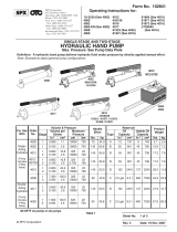
Hydraulic Circuit Diagram:
Power Unit Operation:
This modular power unit provides electric-hydraulic power to extend and retract
the piston of one or more cylinders. Piston motion is utilized in various ways, such
as raising and lowering a tabletop, rotating a drum or garbage chute, and moving a
carriage (e.g. forks or platform). Piston motion is driven by a gear-type pump
directly coupled to an electric motor. Many components of the hydraulic system are
housed inside a manifold which is bolted to the gear pump. All components are
rated for 3,000psi working pressure.
Noteworthy elements of the hydraulic system include the following:
1. Selector switch: for the hand control and dashboard pushbuttons to
operate, the selector switch must be turned to the ON position.
2. Hand control: connects to the power unit via a pigtail cord. The control has
2 buttons: UP and DOWN. The UP button causes the piston to extend. The
DOWN button allows the piston to retract.
• Extending the piston: Pressing the UP button activates the electric motor. The motor
turns the pump. As the pump rotates, oil is drawn from the reservoir, passes through
the suction filter, and enters the pump. The pump pushes oil through the check
valve and to the cylinder. As the cylinder fills with oil, the piston extends.
o Releasing the button turns off the motor. The piston maintains its position until
a control button is pressed.
o Limit switches, if included in the electrical circuit of your product, also shut off
the motor. (See Electric Circuit Diagram(s) in the owner’s manual for your
product).
• Retracting the piston: Pressing the DOWN button activates the lowering solenoid valve. When the valve opens,
oil can bypass the check valve and flow to the reservoir (through return hoses). Oil flow to the reservoir is
regulated by the pressure compensated flow control valve. Regulating the volume of oil that can flow through
the spool, the piston retraction speed is kept constant.
o Releasing the button closes the lowering solenoid valve. The piston maintains its position until a control
button is pressed.
o Limit switches, if included in the electrical circuit of your product, also shut off the motor. (See Electric
Circuit Diagram(s) in your owner’s manual).
3. Dashboard pushbuttons (2-Pushbuttons models only): the buttons are labeled “RAISE” and “LOWER”. Pressing
the RAISE button causes the piston to extend. Pressing the LOWER button retracts the piston.
UP
DOWN
HAND
CONTROL
Item
Description
Qty.
1
Manifold
1
2
Motor
1
3
Gear pump
1
4
Cylinder, ram style
2
5
Relief valve, 210 bar, size 08
1
6
Inlet screen, 100 mesh 2” pancake
1
7
Flow control, pressure compensated
1
8
Velocity fuse, adjustable, brass
2
9
Lowering solenoid valve, cartridge, NC,
no coil, w/ nut
1
10
Check valve
1
11
Reservoir
1
Cover
Dashboard
Lower lip
Selector
Switch
LOWER
push-
button
Locking
pin
RAISE
pushbutton
MPU ASSEMBLY

Table of Contents Rev. 11/27/2018 MPU-DC GEN2, MANUAL
Table of Contents Copyright 2018 Vestil Manufacturing Co. Page 19 of 23
4. Electric motor: the motor is either AC powered (wall socket) or DC powered (battery). The motor is activated
whenever the user presses a button (up or down) on the hand control.
• AC-powered motors can be wired for either single-phase or three-phase operation. Regardless of phase
configuration, every motor is dual-voltage capable.
• Power for 12V DC-powered motors operate is provided by one 12V DC deep cycle battery. 24V power units
use two (2) 12V batteries.
5. Pump: the pump shaft is directly coupled to the shaft of the electric motor. Several displacements are available to
match the horsepower of the motor.
6. Check valve: restricts oil flow to one direction through the circuit by preventing oil backflow through the pump to the
reservoir. Without a check valve, oil would return to the reservoir after the motor (and pump) stop. Oil can only flow
in response to an electrical signal from the hand control. This allows the piston to maintain any degree of
extension.
7. (Pressure) Relief valve: prevents system pressure from exceeding 3000psi. The valve opens a path for oil to follow
to the reservoir without traveling to the cylinder if pressure in the system exceeds 3,000psi.
8. Lowering solenoid valve: electrically-operated cartridge valve that activates when the DOWN button is pressed.
The valve has an integral screen to prevent contaminants from entering it.
9. Pressure compensated flow control spool: regulates the flow of oil to the reservoir when the lowering valve opens.
The spool is located beneath the lowering valve. It allows the piston to retract at a set, constant rate regardless of
the load applied (e.g. on the forks, platform, chute, tabletop, etc.). Several sizes are available.
10. Cylinder (not part of the modular power unit): the modular power unit controls movement of one or more
displacement style cylinders. As oil fills the cylinder, it pushes the piston out of the cylinder. Each cylinder includes
a bleeder valve at the top end. The valve allows air to be removed from the cylinder.
11. Velocity fuse: a safety device installed in the hose port of each cylinder. If a failure occurs that results in a sudden
loss of hydraulic pressure (e.g. punctured hose, leaking fitting or coupling), the velocity fuse automatically closes.
By closing, the fuse traps oil in the cylinder and prevents the piston from retracting. The piston remains stationary
until pressure is reapplied to the system.
NOTE: Air in the hydraulic system can also cause the velocity fuse to close even though no failure occurred.
To reset (open) the fuse, unload the work surface (forks, tabletop, chute, platform, etc.). Press and release the
UP button several times. Then, extend and retract the piston completely to purge air from the system.
12. Hydraulic fluid: HO150 hydraulic fluid. To replenish the fluid, add anti-wear hydraulic fluid with a viscosity grade
of 150 SUS at 100°F (ISO 32 @ 40°C) like AW-32 or Dexron transmission fluid.
Removing the Cover: [Refer to MPU Assembly diagram on p. 18]
To access the internal components of the power unit, the plastic cover must be removed. First, remove the locking
pins to disconnect the dashboard from the metal frame. Open the dashboard by lifting the front lip and rotating it up to
a vertical position. Grasp the rear edges of the cover and pull them away from each other. The cover will disengage
the frame. Reinstall the cover by reversing these steps.
Cleaning the Lowering Solenoid Valve: [Detail Views D & E, item 7, p. 17; manifold port RV]
NOTE: This instruction does not apply to pneumatic (air) power units.
If the piston slowly retracts without pressing the DOWN button, then the lowering solenoid valve might not be
closing properly. The valve should be removed and cleaned.
Unload the work surface of your unit (e.g. forks, tabletop, chute, or platform).
Completely retract the piston.
Lock out electrical power. Tag the unit “Out of Service”. Turn the selector switch to the OFF position.
Remove the cover to access the internal components. Then, remove the nut that fastens the solenoid coil to the
valve stem.
Remove the coil and unscrew the valve from the manifold.
Inspect the valve for blockage.
Inspect O-rings and back-up washers for damage such as cuts and tears.
Submerge the valve in mineral spirits or kerosene.
Use a thin tool, such as a small screwdriver or a hex wrench, to push the poppet in and out several times from the
bottom end of the valve. The valve should move freely, about 1/16” between the closed and open positions. If the
poppet sticks, examine the valve stem to determine if it is bent. Replace the valve if it doesn’t move freely after
cleaning.
Remove mineral oil from the valve with compressed air.
Inspect the bottom of the valve cavity in the manifold for foreign matter.
With the thin tool, press the middle of the flow control spool, which is located in the bottom of the cavity. It should
move up-and-down smoothly.
Reinstall the valve in the manifold. Tighten it with a torque wrench to 20 lb∙ft of torque.

Table of Contents Rev. 11/27/2018 MPU-DC GEN2, MANUAL
Table of Contents Copyright 2018 Vestil Manufacturing Co. Page 20 of 23
Bleeding Air from Hydraulic System:
If the piston retracts extremely slowly or does not retract when the DOWN button is pressed, air might be caught in
the cylinder. Air can cause the velocity fuse(s) to close. When the velocity fuse is closed, the piston will not retract. To
correct this issue, bleed air from the system. A bleeder screw is located at the top of each cylinder Study the
appropriate “Exploded view” in the owner’s manual for your product to locate the bleeder screw. The bleeder screw
includes a hose fitting for a small diameter hose. By attaching a hose to the screw, any oil that escapes during the
bleeding process can be directed into a container for proper disposal.
Unload your unit.
If your product includes a maintenance stop, move it into maintenance position. Push the DOWN button until the
work surface is entirely supported by the stop.
Locate the bleeder valve located at the top of the cylinder (it looks like a grease zerk; see the corresponding
“Exploded View” in the owner’s manual for your product). Hold a rag over the valve. Open it about a half turn with a
wrench (turn the hex until air begins to escape). Oil and air will sputter from the valve.
Jog the motor a few times by briefly pressing and then releasing the UP button. If air continues to escape from the
bleeder valve, jog the motor several more times. Wait at least a few seconds between jogs.
Close the valve once air no longer is heard or seen bubbling out of the valve. Just a clear stream of oil should be
seen flowing from the bleeder valve.
Remove the cover from the modular power unit. Check the oil level in the reservoir. If the surface of the oil is lower
than 1 to 1½ in. below the fill port, then add oil. Use anti-wear hydraulic fluid with a viscosity grade of 150 SUS at
100°F (ISO 32 @ 40°C) like AW-32 or Dexron transmission fluid.
Recharging the Battery:
To recharge the battery, you must provide a suitable 3-prong extension cord. The extension cord should be as
short and as thick as possible to minimize the output of the charger due to voltage drop in the line. Plug your
extension cord into the flanged inlet on the back of the MPU cover. Plug the other end of the cord into an 115VAC,
60Hz outlet. When connected to a power source, the LED display on the charger, or the optional battery charge
indicator on the dashboard/lid, displays the charge status:
a. Red only: charger is providing full output to the battery.
b. Red and Green: charger is topping off the battery.
c. Green only: battery is completely charged. The charger is providing a float (maintenance) charge.
[NOTE: LED’s are not visible unless the cover is removed from the MPU.]
The charger is current limited and cannot exceed its rated output. This means that even if loads are placed on the
battery while charging (raising and lowering a tabletop while charging the battery, for example) current will not exceed
the rated output.
Written Record:
Before putting your product into regular service, make a written record that describes the appearance and function
of the modular power unit. Page 3 of this manual provides a space for notes. Remove the cover and photograph the
internal components. Describe their appearance in writing. Record the oil level in the reservoir by marking it in a few
places with a permanent marker. Describe the electrical connections. Replace the cover and turn on the power unit.
Use the hand control to extend and retract the piston (raise and lower the tabletop/forks). Describe the sound of the
power unit as the piston extends and retracts. Indicate whether the piston extends/retracts smoothly.
Inspections and Maintenance:
Review the “Inspections & Maintenance” section of the owner’s manual for your product. Put the product into
recommended inspection configuration (e.g. apply maintenance props) before performing the following inspections
and maintenance.
DO NOT inspect the power unit or perform any repairs or maintenance on it unless the selector switch is OFF.
(A) Before each use, check the cart for any of the following conditions:
• Oil leaks
• Pinched or chafed hoses
• Damaged electrical cords/hand control
(B) At least once per month, remove the cover and:
• Check the oil level. Oil should be 1in. to 1
1
/
2
in. below the top of the reservoir/tank (item no. 2 on pages 14
& 15) when the piston is completely retracted. Add oil, if necessary. Only use AW-32 hydraulic fluid or its
equivalent. If the oil looks milky, water is present and must be replaced.
• Check for oil leaks. Resolve the issue as described in Troubleshooting on p. 21-22.
• Check hand control and pigtail cord for severe wear.
• Examine battery terminals. Remove deposits accumulated on battery terminals.
• Cycle the piston. Watch for binding. Listen for unusual noises. See Troubleshooting.
/