Page is loading ...

Table of Contents Rev. 11/27/2018 MPU-AC GEN2, MANUAL
Table of Contents Copyright 2018 Vestil Manufacturing Co. Page 1 of 23
MPU-AC GEN2 AC-Powered Modular Power Unit
Instruction Manual
Receiving instructions:
After delivery, remove the packaging from the product. Inspect the product closely to determine whether
it sustained damage during transport. If damage is discovered, record a complete description of it on the
bill of lading. If the product is undamaged, discard the packaging.
NOTE:
The end-user is solely responsible for confirming that product design, use, and maintenance comply with
laws, regulations, codes, and mandatory standards applied where the product is used.
Replacement Parts and Technical Assistance:
For answers to questions not addressed in these instructions and to order replacement parts, labels,
and accessories, call our Technical Service and Parts Department at (260) 665-7586. The department can
also be contacted online at http://www.vestilmfg.com/parts_info.htm.
Vestil Manufacturing Corp.
2999 North Wayne Street, P.O. Box 507, Angola, IN 46703
Telephone: (260) 665-7586 -or- Toll Free (800) 348-0868
Fax: (260) 665-1339
Web: www.vestilmfg.com e-mail: info@vestil.com
Table of Contents
Signal Words….………………………………………………………………………………………………………………………….... 2
Hazards of Improper Use…..………………………..…………………………………..………………………………………..……… 2
NOTES……………………………………………………………….....…
………...........................................................................3, 4
115
V or 208-230V AC, Single Phase, 2-Pushbuttons Power Unit Assembly Exploded View and Bill of Materials…………..5, 6
115V or 208-230V AC, Single Phase, No Pushbuttons Power Unit Assembly Exploded View and Bill of Materials…………7, 8
208-230V or 460V AC, Three Phase, 2-Pushbuttons Power Unit Assembly Exploded View and Bill of Materials……….…9, 10
208-230V or 460V AC, Three Phase, No Pushbuttons Power Unit Assembly Exploded View and Bill of Materials………11, 12
115V or 208-230V AC, Single Phase Power Unit Subassembly Exploded View and Bill of Materials……………………..……13
208-230V or 460V AC, 3-Phase Power Unit Subassembly Exploded View and Bill of Materials…………………………...……14
Detail View A: Single Phase, 115V or 208-230V AC, 0.75HP, 1725rpm Motor + Pump Subassembly ……………………….. 15
Detail View B: Single Phase, 115V or 208-230V AC, 2HP, 3450rpm Motor + Pump Subassembly………………………...…..15
Detail View C: 3-Phase, 208-230V or 460V AC, 2HP, 1725rpm Motor + Pump Subassembly...……………………………….. 16
Detail View D: 3-Phase, 208-230V or 460V AC, 2HP, 3450rpm Motor + Pump Subassembly…………………….…………… 16
Detail View E: Manifold Subassembly (Combines with 1 Motor + Pump Subassembly from Detail Views A-D)….……………17
Hydraulic Circuit Diagram……………………………………………………………………………………………………….….…….17
Power Unit Operation…………………….……………………………………………………………………………………………….18
Removing the Cover……………………………………………………………………………………………………………………....19
Cleaning the Lowering Solenoid Valve……………………………………………………………………………………………........19
Bleeding Air from Hydraulic System………………………………………………………………………………………………….....19
Written Record…………………………………………………………………………………………………………………………..…19
Inspections and Maintenance……………………………………………………………………......................................................20
Labeling Diagram……...…………………………………………………………………………………………………………….........20
Troubleshooting………………………………………………………………………….………………………………………......21 - 22
Limited Warranty…...……………………………………………………………………………………………………………………..
.23

Table of Contents Rev. 11/27/2018 MPU-AC GEN2, MANUAL
Table of Contents Copyright 2018 Vestil Manufacturing Co. Page 2 of 23
SIGNAL WORDS
This manual uses SIGNAL WORDS to identify hazards that could occur while using this product. DANGER,
WARNING, and CAUTION draw attention to hazards likely to cause personal injuries. Each signal word implies a
specific level of injury. NOTICE is used to indicate hazards likely to result in property damage. The following are
definitions for each word:
Identifies a hazardous situation which, if not avoided, WILL result in DEATH or SERIOUS
INJURY. Use of this signal word is limited to the most extreme situations.
Identifies a hazardous situation which, if not avoided, COULD result in DEATH or SERIOUS
INJURY.
Indicates a hazardous situation which, if not avoided, COULD result in MINOR or MODERATE
injury.
Identifies practices likely to result in product/property damage, such as operation that might
damage the product.
Hazards of Improper Use:
We strive to identify all hazards that could occur while using our products, but no manual can address every
risk. The most effective means for avoiding injury is to exercise sound judgment whenever using this device.
Read the entire manual carefully before installing, using, or servicing the product. Vestil recommends that you
contact its Technical Service Department
(the “TSD”) if you have any questions about instructions in the manual.
You should also contact the TSD if you believe that a necessary instruction is missing or inaccurate.
Improper or careless operation might result in serious personal injuries.
• Read and understand the entire manual before using or servicing the power unit. Read the manual to
refresh your understanding of proper use and maintenance procedures whenever necessary.
• All wiring to electrical power supplies must conform to the national electrical code (NEC) as adopted in your
location (where the product is used). Having all necessary wiring installed only by licensed electricians is
strongly recommended.
• Only authorized, qualified personnel should perform service on the electrical system.
• DO NOT service this power unit unless the product it provides power to (e.g. cart, table, lift, etc.) is unloaded.
Read the “Inspections & Maintenance” section of your product owner’s manual. Put the product into the
recommended maintenance configuration. If repairs are necessary, ONLY install manufacturer-approved
replacement parts.
• DO NOT use the power unit unless it is in normal condition (see “Inspections & Maintenance” on p. 20).
• Watch the cylinder while extending and retracting the piston. It should move smoothly. Watch for binding or
jerky movement and listen for unusual noises. Tag the unit "Out of order" and do not use it if you observe
anything abnormal.
• DO NOT continue to press the UP button if the piston is fully extended.
• DO NOT use the power unit UNLESS all labels are in place and readable (see “Labeling diagram” on p. 20).
• DO NOT modify this power unit in any way. Modifications automatically void the limited warranty and might
make the unit unsafe to use.
Proper use and maintenance are essential for this product to function properly.
• Periodically lubricate moving parts.
• Keep the product clean & dry. Only use and store the product indoors.
• Only use approved replacement parts. To order replacement or spare parts for this equipment, contact the
factory.


Table of Contents Rev. 11/27/2018 MPU-AC GEN2, MANUAL
Table of Contents Copyright 2018 Vestil Manufacturing Co. Page 5 of 23
POWER UNIT ASSEMBLY: 115V AC OR 208-230V AC
99-660-(073-096)-MANUALS SINGLE PHASE, 0.75HP, 1725RPM OR 2HP, 3450RPM MOTOR,
DASHBOARD WITH 2 PUSHBUTTONS
USER SELECTED PUMP DISPLACEMENT AND FLOW CONTROL
L-H-L HYDRAULIC CIRCUIT

Table of Contents Rev. 11/27/2018 MPU-AC GEN2, MANUAL
Table of Contents Copyright 2018 Vestil Manufacturing Co. Page 6 of 23
2-PUSHBUTTONS POWER UNIT ASSEMBLY BILL OF MATERIALS
SINGLE PHASE; 115V OR 208-230V AC; 0.75HP, 1725RPM OR 2HP, 3450RPM MOTOR
USER SELECTED PUMP DISPLACEMENT AND FLOW CONTROL
Item Part no. Description Qty. Item Part no. Description Qty.
1 99-514-021
FRAME, MPU GEN2 1 15
99-128-005
CONTACTOR, MOTOR, 3-POLE,
24V AC
1
2
99-160-173
99-160-218
2-PUSHBUTTON DASHBOARD:
115V AC, 1-PH
230V AC, 1-PH
1 16
99-145-142
LOCKING PIN WITH RING,
3
/
16
”DIA. X 1
1
/
4
” EFFECTIVE
LENGTH
2
3
POWER UNIT SUBASSEMBLY: 115V OR 208-230AC, 1-PHASE,
0.75HP, 1725RPM MOTOR; L-H-L CIRCUIT; 1.5 GAL.
HORIZONTAL TANK & FITTINGS; PLUS 1 OF THE FOLLOWING
PUMP + FLOW CONTROL COMBINATIONS
(SEE “POWER UNIT SUBASSEMBLY” ON P. 13)
3
POWER UNIT SUBASSEMBLY: 115V OR 208-230AC, 1-PHASE,
2HP, 3450RPM MOTOR; L-H-L CIRCUIT; 1.5 GAL.
HORIZONTAL TANK & FITTINGS; PLUS 1 OF THE FOLLOWING
PUMP + FLOW CONTROL COMBINATIONS
(SEE “POWER UNIT SUBASSEMBLY” ON P. 13)
99-160-176
99-160-177
99-160-178
99-160-179
99-160-180
99-160-181
99-160-182
99-160-183
99-160-184
99-160-185
99-160-186
99-160-187
99-160-188
99-160-189
99-160-190
0.060 DISPLACEMENT PUMP:
0.5GPM FLOW CONTROL
1.0GPM FLOW CONTROL
1.5GPM FLOW CONTROL
2.0GPM FLOW CONTROL
0.073 DISPLACEMENT PUMP:
0.5GPM FLOW CONTROL
1.0GPM FLOW CONTROL
1.5GPM FLOW CONTROL
2.0GPM FLOW CONTROL
0.122 DISPLACEMENT PUMP:
1.0GPM FLOW CONTROL
1.5GPM FLOW CONTROL
2.0GPM FLOW CONTROL
0.153 DISPLACEMENT PUMP:
0.5GPM FLOW CONTROL
1.0GPM FLOW CONTROL
1.5GPM FLOW CONTROL
2.0GPM FLOW CONTROL
1
1
1
1
1
1
1
1
1
1
1
1
1
1
1
99-160-191
99-160-192
99-160-193
99-160-194
99-160-195
99-160-196
99-160-197
99-160-198
99-160-199
0.060 DISPLACEMENT PUMP:
0.5GPM FLOW CONTROL
2.0GPM FLOW CONTROL
0.073 DISLACEMENT PUMP:
0.5GPM FLOW CONTROL
1.0GPM FLOW CONTROL
1.5GPM FLOW CONTROL
2.0GPM FLOW CONTROL
0.122 DISPLACEMENT PUMP:
1.0GPM FLOW CONTROL
2.0GPM FLOW CONTROL
0.153 DISPLACEMENT PUMP:
1.5GPM FLOW CONTROL
1
1
1
1
1
1
1
1
1
4 01-029-006 CONTROL BOX, 6”x6”x4” 1
17
99-533-064
ASSEMBLY, VESTIL MOD.,
CORD, STRAIGHT, 18/5, 15”
MOLDED FEMALE
RECEPTACLE, 5-PIN
1
5 01-033-011 CONNECTOR, COIL, COMMON 1
18
99-533-066
ASSEMBLY, VESTIL MOD.,
CORD, STRAIGHT, 18/2, 30”
MOLDED FEMALE
RECEPTACLE, 2-PIN
1
6 01-129-001
TRANSFORMER, CONTROL, 24V,
40VA
1
19
11003
HEX BOLT, GR. A, Z-PLATED,
1
/
4
”-
20X
3
/
4
”
8
7 99-016-076
BRACKET, CLAMP PLATE, BACK
CONNECTION
1
20
11053
BOLT, HHCS, #2, Z-PLATED,
5
/
16
”-
18X
3
/
4
”
4
8 99-024-036
COVER, POWER UNIT, DC, GEN.
II
1
21
31802
SELF-TAPPING SCREW, #8-
18X
1
/
2
”
4
9 99-033-070
CORD, STRAIGHT, 14/4 & 18/2,
18” BLUNT CUT BOTH ENDS
1 22 33004
FLAT WASHER, USS, Z-PLATED,
1
/
4
”
4
10 99-034-037
ACCESSORIES, ELECTRICAL,
ROMEX, 0.375”
5
23 33006
FLAT WASHER, Z-PLATED, USS,
1
/
4
”
8
11 99-034-042
RAIN, DIN, ALUMINUM 1
24 33618
MEDIUM SPLIT LOCK WASHER,
1
/
4
”
8
12 99-034-074
ACCESSORIES, ELECTRICAL,
TERMINAL BLOCK
1
25 33620
MEDIUM SPLIT LOCK WASHER,
5
/
16
”
4
13
99-034-084
ELECTRICAL CORD, CLAMP
PLATE
1
26 36102
HEX NUT, GR. A, Z-PLATED,
1
/
4
”-
20
8
14
99-034-147
RING TERMINAL, BLUE, #8, 14-
16GA. WIRE
3
27 36104
HEX NUT GR. A, Z-PLATED,
5
/
16
”-
18
4
28 H-9X450 TIE STRAP, BLACK 1

Table of Contents Rev. 11/27/2018 MPU-AC GEN2, MANUAL
Table of Contents Copyright 2018 Vestil Manufacturing Co. Page 7 of 23
POWER UNIT ASSEMBLY: 115V AC OR 208-230V AC
99-660-(114-137)-MANUALS SINGLE PHASE, 0.75HP, 1725RPM OR 2HP, 3450RPM MOTOR
DASHBOARD WITHOUT PUSHBUTTONS
USER SELECTED PUMP DISPLACEMENT AND FLOW CONTROL
L-H-L HYDRAULIC CIRCUIT

Table of Contents Rev. 11/27/2018 MPU-AC GEN2, MANUAL
Table of Contents Copyright 2018 Vestil Manufacturing Co. Page 8 of 23
0-PUSHBUTTONS POWER UNIT ASSEMBLY BILL OF MATERIALS
SINGLE PHASE; 115V AC OR 208-230V AC; 0.75HP, 1725RPM OR 2HP, 3450RPM MOTOR;
USER SELECTED PUMP DISPLACMENT AND FLOW CONTROL
Item Part no. Description Qty. Item Part no. Description Qty.
1 99-514-021
FRAME, MPU GEN2 1 15
99-128-005
CONTACTOR, MOTOR, 3-POLE,
24V AC
1
2
99-160-174
99-160-219
0-PUSHBUTTON DASHBOARD:
115V AC, 1-PH
230V AC, 1-PH
1 16
99-145-142
LOCKING PIN WITH RING,
3
/
16
”DIA. X 1
1
/
4
” EFFECTIVE
LENGTH
2
3
POWER UNIT SUBASSEMBLY: 115V OR 208-230AC, 1-PHASE,
0.75HP, 1725RPM MOTOR; L-H-L CIRCUIT; 1.5 GAL.
HORIZONTAL TANK & FITTINGS; PLUS 1 OF THE FOLLOWING
PUMP + FLOW CONTROL COMBINATIONS
(SEE “POWER UNIT SUBASSEMBLY” ON P. 13)
3
POWER UNIT SUBASSEMBLY: 115V OR 208-230AC, 1-PHASE,
2HP, 3450RPM MOTOR; L-H-L CIRCUIT; 1.5 GAL.
HORIZONTAL TANK & FITTINGS; PLUS 1 OF THE FOLLOWING
PUMP + FLOW CONTROL COMBINATIONS
(SEE “POWER UNIT SUBASSEMBLY” ON P. 13)
99-160-176
99-160-177
99-160-178
99-160-179
99-160-180
99-160-181
99-160-182
99-160-183
99-160-184
99-160-185
99-160-186
99-160-187
99-160-188
99-160-189
99-160-190
0.060 DISPLACEMENT PUMP:
0.5GPM FLOW CONTROL
1.0GPM FLOW CONTROL
1.5GPM FLOW CONTROL
2.0GPM FLOW CONTROL
0.073 DISPLACEMENT PUMP:
0.5GPM FLOW CONTROL
1.0GPM FLOW CONTROL
1.5GPM FLOW CONTROL
2.0GPM FLOW CONTROL
0.122 DISPLACEMENT PUMP:
1.0GPM FLOW CONTROL
1.5GPM FLOW CONTROL
2.0GPM FLOW CONTROL
0.153 DISPLACEMENT PUMP:
0.5GPM FLOW CONTROL
1.0GPM FLOW CONTROL
1.5GPM FLOW CONTROL
2.0GPM FLOW CONTROL
1
1
1
1
1
1
1
1
1
1
1
1
1
1
1
99-160-191
99-160-192
99-160-193
99-160-194
99-160-195
99-160-196
99-160-197
99-160-198
99-160-199
0.060 DISPLACEMENT PUMP:
0.5GPM FLOW CONTROL
2.0GPM FLOW CONTROL
0.073 DISLACEMENT PUMP:
0.5GPM FLOW CONTROL
1.0GPM FLOW CONTROL
1.5GPM FLOW CONTROL
2.0GPM FLOW CONTROL
0.122 DISPLACEMENT PUMP:
1.0GPM FLOW CONTROL
2.0GPM FLOW CONTROL
0.153 DISPLACEMENT PUMP:
1.5GPM FLOW CONTROL
1
1
1
1
1
1
1
1
1
4 01-029-006 CONTROL BOX, 6”x6”x4” 1
17
99-533-064
ASSEMBLY, VESTIL MOD.,
CORD, STRAIGHT, 18/5, 15”
MOLDED FEMALE
RECEPTACLE, 5-PIN
1
5 01-033-011 CONNECTOR, COIL, COMMON 1
18
99-533-066
ASSEMBLY, VESTIL MOD.,
CORD, STRAIGHT, 18/2, 30”
MOLDED FEMALE
RECEPTACLE, 2-PIN
1
6 01-129-001
TRANSFORMER, CONTROL, 24V,
40VA
1
19
11003
HEX BOLT, GR. A, Z-PLATED,
1
/
4
”-
20X
3
/
4
”
8
7 99-016-076
BRACKET, CLAMP PLATE, BACK
CONNECTION
1
20
11053
BOLT, HHCS, #2, Z-PLATED,
5
/
16
”-
18X
3
/
4
”
4
8 99-024-036
COVER, POWER UNIT, DC, GEN.
II
1
21
31802
SELF-TAPPING SCREW, #8-
18X
1
/
2
”
4
9 99-033-070
CORD, STRAIGHT, 14/4 & 18/2,
18” BLUNT CUT BOTH ENDS
1 22 33004
FLAT WASHER, USS, Z-PLATED,
1
/
4
”
4
10 99-034-037
ACCESSORIES, ELECTRICAL,
ROMEX, 0.375”
5
23 33006
FLAT WASHER, Z-PLATED, USS,
1
/
4
”
8
11 99-034-042
RAIN, DIN, ALUMINUM 1
24 33618
MEDIUM SPLIT LOCK WASHER,
1
/
4
”
8
12 99-034-074
ACCESSORIES, ELECTRICAL,
TERMINAL BLOCK
1
25 33620
MEDIUM SPLIT LOCK WASHER,
5
/
16
”
4
13
99-034-084
ELECTRICAL CORD, CLAMP
PLATE
1
26 36102
HEX NUT, GR. A, Z-PLATED,
1
/
4
”-
20
8
14
99-034-147
RING TERMINAL, BLUE, #8, 14-
16GA. WIRE
3
27 36104
HEX NUT GR. A, Z-PLATED,
5
/
16
”-
18
4
28 H-9X450 TIE STRAP, BLACK 1

Table of Contents Rev. 11/27/2018 MPU-AC GEN2, MANUAL
Table of Contents Copyright 2018 Vestil Manufacturing Co. Page 9 of 23
POWER UNIT ASSEMBLY: 208-230VAC & 460V AC
99-660-(097-104)-MANUALS 3-PHASE, 2HP, 1725RMP MOTOR
DASHBOARD WITH 2-PUSHBUTTONS
USER SELECTED PUMP DISPLACEMENT & FLOW CONTROL
L-H-L HYDRAULIC CIRCUIT

Table of Contents Rev. 11/27/2018 MPU-AC GEN2, MANUAL
Table of Contents Copyright 2018 Vestil Manufacturing Co. Page 10 of 23
2-PUSHBUTTONS POWER UNIT ASSEMBLY BILL OF MATERIALS
3-PHASE; 208-230V AC & 460V AC; 2HP, 1725RPM OR 3450RPM MOTOR;
USER SELECTED PUMP DISPLACMENT AND FLOW CONTROL
Item Part no. Description Qty. Item Part no. Description Qty.
1 99-514-021 FRAME, MPU GEN2 1 15
99-128-005
CONTACTOR, MOTOR, 3-POLE,
24V AC
1
2
99-160-220 2-PUSHBUTTON DASHBOARD
1 16
99-145-142
LOCKING PIN WITH RING,
3
/
16
”DIA. X 1
1
/
4
” EFFECTIVE
LENGTH
2
3
POWER UNIT SUBASSEMBLY: 115V OR 208-230AC, 3-PHASE,
0.75HP, 1725RPM MOTOR; L-H-L CIRCUIT; 1.5 GAL.
HORIZONTAL TANK & FITTINGS; PLUS 1 OF THE FOLLOWING
PUMP + FLOW CONTROL COMBINATIONS
(SEE “POWER UNIT SUBASSEMBLY” ON P. 14)
3
POWER UNIT SUBASSEMBLY: 115V OR 208-230AC, 3-PHASE,
2HP, 3450RPM MOTOR; L-H-L CIRCUIT; 1.5 GAL.
HORIZONTAL TANK & FITTINGS; PLUS 1 OF THE FOLLOWING
PUMP + FLOW CONTROL COMBINATIONS
(SEE “POWER UNIT SUBASSEMBLY” ON P. 14)
99-160-200
99-160-201
99-160-202
99-160-203
99-160-204
99-160-205
99-160-206
99-160-207
0.060 DISPLACEMENT PUMP:
0.5GPM FLOW CONTROL
0.122 DISPLACEMENT PUMP:
1.0GPM FLOW CONTROL
1.5GPM FLOW CONTROL
2.0GPM FLOW CONTROL
0.153 DISPLACEMENT PUMP:
0.5GPM FLOW CONTROL
1.0GPM FLOW CONTROL
1.5GPM FLOW CONTROL
2.0GPM FLOW CONTROL
1
1
1
1
1
1
1
1
99-160-208
99-160-209
99-160-210
99-160-211
99-160-212
99-160-213
99-160-214
99-160-215
99-160-216
0.060 DISPLACEMENT PUMP:
0.5GPM FLOW CONTROL
0.073 DISLACEMENT PUMP:
0.5GPM FLOW CONTROL
1.0GPM FLOW CONTROL
1.5GPM FLOW CONTROL
2.0GPM FLOW CONTROL
0.122 DISPLACEMENT PUMP:
1.0GPM FLOW CONTROL
2.0GPM FLOW CONTROL
0.153 DISPLACEMENT PUMP:
1.5GPM FLOW CONTROL
2.0GPM FLOW CONTROL
1
1
1
1
1
1
1
1
1
4
01-029-006 CONTROL BOX, 6”x6”x4” 1
17
99-533-064
ASSEMBLY, VESTIL MOD.,
CORD, STRAIGHT, 18/5, 15”
MOLDED FEMALE
RECEPTACLE, 5-PIN
1
5
01-033-011 CONNECTOR, COIL, COMMON 1
18
99-533-066
ASSEMBLY, VESTIL MOD.,
CORD, STRAIGHT, 18/2, 30”
MOLDED FEMALE
RECEPTACLE, 2-PIN
1
6
01-129-001
TRANSFORMER, CONTROL, 24V,
40VA
1
19
11003
HEX BOLT, GR. A, Z-PLATED,
1
/
4
”-
20X
3
/
4
”
8
7
99-016-076
BRACKET, CLAMP PLATE, BACK
CONNECTION
1
20
11053
BOLT, HHCS, #2, Z-PLATED,
5
/
16
”-
18X
3
/
4
”
4
8
99-024-036 COVER, MPU, AC, GEN. II
1 21
31802
SELF-TAPPING SCREW, #8-
18X
1
/
2
”
4
9
99-033-070
CORD, STRAIGHT, 14/4 & 18/2,
18” BLUNT CUT BOTH ENDS
1 22 33004
FLAT WASHER, USS, Z-PLATED,
1
/
4
”
4
10 99-034-037
ACCESSORIES, ELECTRICAL,
ROMEX, 0.375”
5
23 33006
FLAT WASHER, Z-PLATED, USS,
1
/
4
”
8
11 99-034-042 RAIN, DIN, ALUMINUM 1
24 33618
MEDIUM SPLIT LOCK WASHER,
1
/
4
”
8
12 99-034-074
ACCESSORIES, ELECTRICAL,
TERMINAL BLOCK
1
25 33620
MEDIUM SPLIT LOCK WASHER,
5
/
16
”
4
13
99-034-084
ELECTRICAL CORD, CLAMP
PLATE
1
26 36102
HEX NUT, GR. A, Z-PLATED,
1
/
4
”-
20
8
14
99-034-147
RING TERMINAL, BLUE, #8, 14-
16GA. WIRE
3
27 36104
HEX NUT GR. A, Z-PLATED,
5
/
16
”-
18
4
28 H-9X450 TIE STRAP, BLACK 1

Table of Contents Rev. 11/27/2018 MPU-AC GEN2, MANUAL
Table of Contents Copyright 2018 Vestil Manufacturing Co. Page 11 of 23
POWER UNIT ASSEMBLY: 208-230VAC & 460V AC
99-660-(138-154)-MANUALS 3-PHASE, 2HP, 1725RMP OR 3450RPM MOTOR
DASHBOARD WITHOUT PUSHBUTTONS
USER SELECTED PUMP DISPLACEMENT FLOW CONTROL
L-H-L HYDRAULIC CIRCUIT

Table of Contents Rev. 11/27/2018 MPU-AC GEN2, MANUAL
Table of Contents Copyright 2018 Vestil Manufacturing Co. Page 12 of 23
0-PUSHBUTTONS POWER UNIT ASSEMBLY BILL OF MATERIALS
3-PHASE; 208-230V AC & 460V AC; 3HP, 1725RPM OR 3450RPM MOTOR;
USER SELECTED PUMP DISPLACEMENT AND FLOW CONTROL
Item Part no. Description Qty. Item Part no. Description Qty.
1 99-514-021
FRAME, MPU GEN2 1 15
99-128-005
CONTACTOR, MOTOR, 3-POLE,
24V AC
1
2
99-160-221 0-PUSHBUTTON DASHBOARD
1 16
99-145-142
LOCKING PIN WITH RING,
3
/
16
”DIA. X 1
1
/
4
” EFFECTIVE
LENGTH
2
3
POWER UNIT SUBASSEMBLY: 115V OR 208-230AC, 3-PHASE,
2HP, 1725RPM MOTOR; L-H-L CIRCUIT; 1.5 GAL.
HORIZONTAL TANK & FITTINGS; PLUS 1 OF THE FOLLOWING
PUMP + FLOW CONTROL COMBINATIONS
(SEE “POWER UNIT SUBASSEMBLY” ON P. 14)
3
POWER UNIT SUBASSEMBLY: 115V OR 208-230AC, 3-PHASE,
2HP, 3450RPM MOTOR; L-H-L CIRCUIT; 1.5 GAL.
HORIZONTAL TANK & FITTINGS; PLUS 1 OF THE FOLLOWING
PUMP + FLOW CONTROL COMBINATIONS
(SEE “POWER UNIT SUBASSEMBLY” ON P. 14)
99-160-200
99-160-201
99-160-202
99-160-203
99-160-204
99-160-205
99-160-206
99-160-207
0.060 DISPLACEMENT PUMP:
0.5GPM FLOW CONTROL
0.122 DISPLACEMENT PUMP:
1.0GPM FLOW CONTROL
1.5GPM FLOW CONTROL
2.0GPM FLOW CONTROL
0.153 DISPLACEMENT PUMP:
0.5GPM FLOW CONTROL
1.0GPM FLOW CONTROL
1.5GPM FLOW CONTROL
2.0GPM FLOW CONTROL
1
1
1
1
1
1
1
1
99-160-208
99-160-209
99-160-210
99-160-211
99-160-212
99-160-213
99-160-214
99-160-215
99-160-216
0.060 DISPLACEMENT PUMP:
0.5GPM FLOW CONTROL
0.073 DISLACEMENT PUMP:
0.5GPM FLOW CONTROL
1.0GPM FLOW CONTROL
1.5GPM FLOW CONTROL
2.0GPM FLOW CONTROL
0.122 DISPLACEMENT PUMP:
1.0GPM FLOW CONTROL
2.0GPM FLOW CONTROL
0.153 DISPLACEMENT PUMP:
1.5GPM FLOW CONTROL
2.0GPM FLOW CONTROL
1
1
1
1
1
1
1
1
1
4
01-029-006 CONTROL BOX, 6”x6”x4” 1
17
99-533-064
ASSEMBLY, VESTIL MOD.,
CORD, STRAIGHT, 18/5, 15”
MOLDED FEMALE
RECEPTACLE, 5-PIN
1
5
01-033-011 CONNECTOR, COIL, COMMON 1
18
99-533-066
ASSEMBLY, VESTIL MOD.,
CORD, STRAIGHT, 18/2, 30”
MOLDED FEMALE
RECEPTACLE, 2-PIN
1
6
01-129-001
TRANSFORMER, CONTROL, 24V,
40VA
1
19
11003
HEX BOLT, GR. A, Z-PLATED,
1
/
4
”-
20X
3
/
4
”
8
7
99-016-076
BRACKET, CLAMP PLATE, BACK
CONNECTION
1
20
11053
BOLT, HHCS, #2, Z-PLATED,
5
/
16
”-
18X
3
/
4
”
4
8
99-024-036 COVER, MPU, DC, GEN. II
1 21
31802
SELF-TAPPING SCREW, #8-
18X
1
/
2
”
4
9
99-033-070
CORD, STRAIGHT, 14/4 & 18/2,
18” BLUNT CUT BOTH ENDS
1 22 33004
FLAT WASHER, USS, Z-PLATED,
1
/
4
”
4
10 99-034-037
ACCESSORIES, ELECTRICAL,
ROMEX, 0.375”
5
23 33006
FLAT WASHER, Z-PLATED, USS,
1
/
4
”
8
11 99-034-042
RAIN, DIN, ALUMINUM 1
24 33618
MEDIUM SPLIT LOCK WASHER,
1
/
4
”
8
12 99-034-074
ACCESSORIES, ELECTRICAL,
TERMINAL BLOCK
1
25 33620
MEDIUM SPLIT LOCK WASHER,
5
/
16
”
4
13
99-034-084
ELECTRICAL CORD, CLAMP
PLATE
1
26 36102
HEX NUT, GR. A, Z-PLATED,
1
/
4
”-
20
8
14
99-034-147
RING TERMINAL, BLUE, #8, 14-
16GA. WIRE
3
27 36104
HEX NUT GR. A, Z-PLATED,
5
/
16
”-
18
4
28 H-9X450 TIE STRAP, BLACK 1

Table of Contents Rev. 11/27/2018 MPU-AC GEN2, MANUAL
Table of Contents Copyright 2018 Vestil Manufacturing Co. Page 13 of 23
Item Part no. Description Qty. Item Part no. Description Qty.
1
MOTOR-PUMP-MANIFOLD SUBASSEMBLY: 115V & 208-230V
AC, 1-PHASE, 0.75HP, 1725RPM MOTOR, L-H-L, 1.5 GAL.
HORIZONTAL TANK & FITTINGS, PLUS 1 OF THE FOLLOWING
PUMP + FLOW CONTROL COMBINATIONS
(SEE DETAIL A ON P. 15 & DETAIL E ON P. 17)
1
MOTOR-PUMP-MANIFOLD SUBASSEMBLY: 115V & 208-230V
AC, 1-PHASE, 2HP, 3450RPM MOTOR, L-H-L, 1.5 GAL.
HORIZONTAL TANK & FITTINGS, PLUS 1 OF THE FOLLOWING
PUMP + FLOW CONTROL COMBINATIONS
(SEE DETAIL B ON P. 15 & DETAIL E ON P. 17)
99-160-044
99-160-045
99-160-046
99-160-047
99-160-048
99-160-049
99-160-050
99-160-051
99-160-052
99-160-053
99-160-054
99-160-055
99-160-056
99-160-057
99-160-058
0.060 DISPLACEMENT PUMP:
0.5GPM FLOW CONTROL
1.0GPM FLOW CONTROL
1.5GPM FLOW CONTROL
2.0GPM FLOW CONTROL
0.073 DISPLACEMENT PUMP:
0.5GPM FLOW CONTROL
1.0GPM FLOW CONTROL
1.5GPM FLOW CONTROL
2.0GPM FLOW CONTROL
0.122 DISPLACEMENT PUMP:
1.0GPM FLOW CONTROL
1.5GPM FLOW CONTROL
2.0GPM FLOW CONTROL
0.153 DISPLACEMENT PUMP:
0.5GPM FLOW CONTROL
1.0GPM FLOW CONTROL
1.5GPM FLOW CONTROL
2.0GPM FLOW CONTROL
1
1
1
1
1
1
1
1
1
1
1
1
1
1
1
99-160-059
99-160-060
99-160-061
99-160-062
99-160-063
99-160-064
99-160-065
99-160-066
99-160-067
0.060 DISPLACEMENT PUMP:
0.5GPM FLOW CONTROL
2.0GPM FLOW CONTROL
0.073 DISPLACEMENT PUMP:
0.5GPM FLOW CONTROL
1.0GPM FLOW CONTROL
1.5GPM FLOW CONTROL
2.0GPM FLOW CONTROL
0.122 DISPLACEMENT PUMP:
1.0GPM FLOW CONTROL
2.0GPM FLOW CONTROL
0.153 DISPLACEMENT PUMP:
1.5GPM FLOW CONTROL
1
1
1
1
1
1
1
1
1
2 99-023-001
RESERVOIR, HYDRAULIC,
1.5GAL., HORIZONTAL
6 99-116-150
FITTING, HYDRAULIC, 08MORB-
06MP, STRAIGHT
3 99-031-029 SCREEN, INLET, 1.75” DIA. 7 99-144-007 O-RING, MANIFOLD, 3” O.D.
4 01-116-003 BREATHER,
1
/
2
” NPT
8 99-145-061
CLAMP, WORM GEAR HOSE,
2
13
/
16
” – 3
3
/
4
”
5 99-116-030
FITTING, HYDRAULIC, 06MJ-
06MORB, STRAIGHT
POWER UNIT SUBASSEMBLY: 115V AC or 208-230V AC, 1-PHASE, 0.75HP OR 2HP MOTOR
ITEM 3 ON P. 6 & P. 8 USER-SELECTED PUMP DISPLACEMENT AND FLOW CONTROL
99-160-(176-199)-MANUALS L-H-L HYDRAULIC CIRCUIT
1.5 GALLON HORIZONTAL TANK
NOTE: ITEM 1 CONSISTS
OF 2 SUBASSEMBLIES:
• MOTOR + PUMP
(DETAIL VIEWS A-D
ON P. 15 & 16)
• MANIFOLD (DETAI
L
V
IEW E ON P. 17)

Table of Contents Rev. 11/27/2018 MPU-AC GEN2, MANUAL
Table of Contents Copyright 2018 Vestil Manufacturing Co. Page 14 of 23
Item Part no. Description Qty. Item Part no. Description Qty.
1
POWER UNIT SUBASSEMBLY: 208-230V or 460V AC, 3-
PHASE, 2HP, 1725RPM MOTOR, L-H-L, 1.5 GAL.
HORIZONTAL TANK & FITTINGS, PLUS 1 OF THE FOLLOWING
PUMP + FLOW CONTROL COMBINATIONS.
SEE DETAIL VIEW C ON P. 16.
1
POWER UNIT SUBASSEMBLY: 208-230V or 460V AC, 3-PHASE,
2HP, 3450RPM MOTOR, L-H-
L, 1.5 GAL. HORIZONTAL TANK &
FITTINGS, PLUS 1 OF THE FOLLOWING PUMP + FLOW
CONTROL COMBINATIONS.
SEE DETAIL VIEW D ON P. 16.
99-160-068
99-160-069
99-160-070
99-160-071
99-160-072
99-160-073
99-160-074
99-160-075
0.060 DISPLACEMENT PUMP:
0.5GPM FLOW CONTROL
0.122 DISPLACEMENT PUMP:
1.0GPM FLOW CONTROL
1.5GPM FLOW CONTROL
2.0GPM FLOW CONTROL
0.153 DISPLACEMENT PUMP:
0.5GPM FLOW CONTROL
1.0GPM FLOW CONTROL
1.5GPM FLOW CONTROL
2.0GPM FLOW CONTROL
1
1
1
1
1
1
1
1
99-160-076
99-160-077
99-160-078
99-160-079
99-160-080
99-160-081
99-160-082
99-160-083
99-160-084
0.060 DISPLACEMENT PUMP:
0.5GPM FLOW CONTROL
0.073 DISPLACEMENT PUMP:
0.5GPM FLOW CONTROL
1.0GPM FLOW CONTROL
1.5GPM FLOW CONTROL
2.0GPM FLOW CONTROL
0.122 DISPLACEMENT PUMP:
1.0GPM FLOW CONTROL
2.0GPM FLOW CONTROL
0.153 DISPLACEMENT PUMP:
1.5GPM FLOW CONTROL
2.0GPM FLOW CONTROL
1
1
1
1
1
1
1
1
1
2 99-023-001
RESERVOIR, HYDRAULIC, 1.5
GAL, HORIZONTAL TANK
1 6 99-116-150
FITTING, HYDRAULIC, 08MORB-
06MP STRAIGHT
1
3
99-031-029
ACCESSORIES, HYDRAULIC
1
7
99-144-007
O-RING, MANIFOLD, 3” OD
1
4
01-116-003
BREATHER,
1
/
2
” NPT
1
8
99-145-061
CLAMP, 2
13
/
16
” – 3
3
/
4
”
1
5 99-116-030
FITTING, HYDRAULIC,
06MJ-06MORB STRAIGHT
1
POWER UNIT SUBASSEMBLY: 208-230V or 460V AC, 3-PHASE, 2HP MOTOR
ITEM 3 ON P. 10 & P. 12 USER-SELECTED PUMP DISPLACEMENT AND FLOW CONTROL
99-160-(200-216)-MANUALS L-H-L HYDRAULIC CIRCUIT
1.5 GALLON HORIZONTAL TANK
NOTE: ITEM 1 CONSISTS
OF 2 SUBASSEMBLIES:
• MOTOR + PUMP
(DETAIL VIEWS A-D
ON P. 15 & 16)
• MANIFOLD (DETAI
L
V
IEW E ON P. 17).

Table of Contents Rev. 11/27/2018 MPU-AC GEN2, MANUAL
Table of Contents Copyright 2018 Vestil Manufacturing Co. Page 15 of 23
DETAIL VIEW A: SINGLE PHASE, 115V OR 208-230V, 0.75HP, 1725RPM MOTOR + PUMP SUBASSEMBLY
COMBINES WITH MANIFOLD SUBASSEMBLY (DETAIL VIEW E ON P. 17)
Item Part no. Description Qty.
1 99-135-003
MOTOR, AC, 0.75HP, 1PH,
1725RPM, 56F, 115V OR 208-
230V, 60HZ, 2.0SF
1
2 01-143-905-002
01-143-906-002
01-143-907-002
01-143-908-002
PUMP, HYDRAULIC GEAR,
TANG SHAFT, MANIFOLD
MOUNT
0.06DISP. 1.0CC/R
0.073DISP. 1.3CC/R
0.122DISP., 2.0CC/R
0.153DISP., 2.7CC/R
1
1
1
1
3 23305
BOLT, SHCS, UTILITY GRADE,
3
/
8
” – 16 X 1”
2
4 33688
LOCK WASHER, HIGH
COLLAR,
3
/
8
”
2
5 96056
WASHER, FLAT,
3
/
8
”
NOMINAL, 0.406”I.D.,
YELLOW ZINC SAE
2
6 99-034-037
ACCESSORIES, ELECTRICAL,
ROMEX 0.375”
1
DETAIL VIEW B: SINGLE PHASE, 115V OR 208-230V, 2.0HP, 3450RPM MOTOR + PUMP SUBASSEMBLY
COMBINES WITH MANIFOLD SUBASSEMBLY (DETAIL VIEW E ON P. 17)
Item Part no. Description Qty.
1 99-135-004
MOTOR, AC, 2.0HP, 1PH,
3450RPM, 56F, 115V OR 208-
230V, 60HZ, 2.0SF
1
2 01-143-905-002
01-143-906-002
01-143-907-002
01-143-908-002
PUMP, HYDRAULIC GEAR,
TANG SHAFT, MANIFOLD
MOUNT
0.06DISP. 1.0CC/R
0.073DISP. 1.3CC/R
0.122DISP., 2.0CC/R
0.153DISP., 2.7CC/R
1
3 23305
BOLT, SHCS, UTILITY GRADE,
3
/
8
” – 16 X 1”
2
4 33688
LOCK WASHER, HIGH
COLLAR,
3
/
8
”
2
5 96056
WASHER, FLAT,
3
/
8
”
NOMINAL, 0.406”I.D.,
YELLOW ZINC SAE
2
6 99-034-037
ACCESSORIES, ELECTRICAL,
ROMEX 0.375”
1
*Diagram from 99-137-(007-010)-(001 & 002)
Suffix -001 = 115V AC
Suffix -002 = 208-230V AC
*Diagram from 99-137-(011-014)-(001 & 002)
Suffix -001 = 115V AC
Suffix -002 = 208-230V AC

Table of Contents Rev. 11/27/2018 MPU-AC GEN2, MANUAL
Table of Contents Copyright 2018 Vestil Manufacturing Co. Page 16 of 23
DETAIL VIEW C: 3-PHASE, 208-230V OR 460V AC, 1725RPM MOTOR + PUMP SUBASSEMBLY
PAIRS WITH MANIFOLD SUBASSEMBLY (DETAIL VIEW E ON P. 17)
Item
Part no. Description Qty.
1 99-135-005
MOTOR, AC, 2.0HP, 1PH,
1725RPM, 56F, 115V OR 208-
230V, 60HZ, 2.0SF
1
2
01-143-905-002
01-143-906-002
01-143-907-002
01-143-908-002
PUMP, HYDRAULIC GEAR,
TANG SHAFT, MANIFOLD
MOUNT
0.06DISP. 1.0CC/R
0.073DISP. 1.3CC/R
0.122DISP., 2.0CC/R
0.153DISP., 2.7CC/R
1
3 23305
BOLT, SHCS, UTILITY GRADE,
3
/
8
” – 16 X 1”
2
4 33688
LOCK WASHER, HIGH
COLLAR,
3
/
8
”
2
5 96056
WASHER, FLAT,
3
/
8
”
NOMINAL, 0.406”I.D.,
YELLOW ZINC SAE
2
6 99-034-037
ACCESSORIES, ELECTRICAL,
ROMEX 0.375”
1
*Diagram from 99-137-(015-018)-(003-& 004)
Suffix -003 = 208-230V AC
Suffix -004 = 460V AC
DETAIL VIEW D: 3-PHASE, 208-230V OR 460V AC, 3450RPM MOTOR + PUMP SUBASSEMBLY
PAIRS WITH MANIFOLD SUBASSEMBLY (DETAIL VIEW E ON P. 17)
Item
Part no. Description Qty.
1 99-135-005
MOTOR, AC, 2.0HP, 1PH,
1725RPM, 56F, 115V OR 208-
230V, 60HZ, 2.0SF
1
2
01-143-905-002
01-143-906-002
01-143-907-002
01-143-908-002
PUMP, HYDRAULIC GEAR,
TANG SHAFT, MANIFOLD
MOUNT
0.06DISP. 1.0CC/R
0.073DISP. 1.3CC/R
0.122DISP., 2.0CC/R
0.153DISP., 2.7CC/R
1
3 23305
BOLT, SHCS, UTILITY GRADE,
3
/
8
” – 16 X 1”
2
4 33688
LOCK WASHER, HIGH
COLLAR,
3
/
8
”
2
5 96056
WASHER, FLAT,
3
/
8
”
NOMINAL, 0.406”I.D.,
YELLOW ZINC SAE
2
6 99-034-037
ACCESSORIES, ELECTRICAL,
ROMEX 0.375”
1
*Diagram from 99-137-(019-022)-(003-& 004)
Suffix -003 = 208-230V AC
Suffix -004 = 460V AC

Table of Contents Rev. 11/27/2018 MPU-AC GEN2, MANUAL
Table of Contents Copyright 2018 Vestil Manufacturing Co. Page 17 of 23
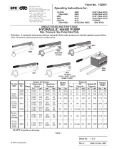
Item
Description
Qty.
1
Manifold
1
2
Motor
1
3
Gear pump
1
4
Cylinder, ram style
2
5
Relief valve, 210 bar, size 08
1
6
Inlet screen, 100 mesh 2” pancake
1
7
Flow control, pressure compensated
1
8
Velocity fuse, adjustable, brass
2
9
Lowering solenoid valve, cartridge, NC,
no coil, w/ nut
1
10
Check valve
1
11
Reservoir
1
DETAIL VIEW E: MANIFOLD SUBASSEMBLY COMBINES WITH PARTICULAR MOTOR + PUMP
SUBASSEMBLY (DETAIL VIEWS A-D)
Item
Part no.
Description
Qty.
1
01-127-010
MANIFOLD, L-H-L
1
2
99-034-008
ACCESSORIES, COIL WITH DIN CONNECTOR
1
3
99-144-008
O-RING, MANIFOLD,
1
/
2
” OD
1
4
99-144-009
O-RING, MANIFOLD,
3
/
4
” OD
1
5
99-153-006
VALVE, PRESSURE RELIEF, 210 BAR
1
6
99-153-011
CHECK VALVE, SIZE 08, NOSE-INSIDE-OUT
1
7
99-153-058
VALVE, SOLENOID, ZERO LEAK, WITH NUT
1
8
99-153-049
99-153-038
99-153-039
99-153-040
FLOW CONTROL, PRESSURE COMPENSATED:
0.5GPM
1.0GPM
1.5GPM
2.0GPM
1
1
1
1
*Diagram from 01-627-(012-015)
Suffix -012 = 0.5gpm flow control
Suffix -013 = 1.0gpm flow control
Suffix -014 = 1.5gpm flow control
Suffix -015 = 2.0gpm flow control
Hydraulic Circuit Diagram:

Table of Contents Rev. 11/27/2018 MPU-AC GEN2, MANUAL
Table of Contents Copyright 2018 Vestil Manufacturing Co. Page 18 of 23
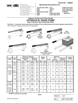
Power Unit Operation:
This modular power unit provides electric-hydraulic power to extend and retract
the piston of one or more cylinders. Piston motion is utilized in various ways, such
as raising and lowering a tabletop, rotating a drum or garbage chute, and moving a
carriage (e.g. forks or platform). Piston motion is driven by a gear-type pump
directly coupled to an electric motor. Many components of the hydraulic system are
housed inside a manifold which is bolted to the gear pump. All components are
rated for 3,000psi working pressure.
1. Selector switch: for the hand control and dashboard pushbuttons to
operate, the selector switch must be turned to the ON position.
2. Hand control: connects to the power unit via a pigtail cord. The control has 2
buttons: UP and DOWN. The UP button causes the piston to extend. The
DOWN button allows the piston to retract.
• Extending the piston: Pressing the UP button activates the electric motor. The motor
turns the pump. As the pump rotates, oil is drawn from the reservoir, passes through
the suction filter, and enters the pump. The pump pushes oil through the check
valve and to the cylinder. As the cylinder fills with oil, the piston extends.
o Releasing the button turns off the motor. The piston maintains its position until
a control button is pressed.
o Limit switches (if included in the electrical circuit of your product) also shut off
the motor. See “Electric Circuit Diagram[s]” in the product owner’s manual.
• Retracting the piston: Pressing the DOWN button activates the lowering solenoid valve. When the valve opens,
oil can bypass the check valve and flow to the reservoir (through return hoses). Oil flow to the reservoir is
regulated by the pressure compensated flow control valve. Regulating the volume of oil that can flow through
the spool, the piston retraction speed is kept constant.
o Releasing the button closes the lowering solenoid valve. The piston maintains its position until a control
button is pressed.
o Limit switches, if included in the electrical circuit of your product, also shut off the motor. (See Electric
Circuit Diagram(s) in your owner’s manual).
3. Dashboard pushbuttons (2-Pushbuttons models only): the buttons are labeled “RAISE” and “LOWER”. Pressing
the RAISE button causes the piston to extend. Pressing the LOWER button retracts the piston.
4. Electric motor: the motor (AC powered, i.e. plugs into a wall socket) is activated whenever the user presses a
button (up or down) on the hand control.
• AC-powered motors can be wired for either single-phase or three-phase operation. Regardless of phase
configuration, every motor is dual-voltage capable.
5. Pump: the pump shaft is directly coupled to the shaft of the electric motor. Several displacements are available to
match the horsepower of the motor.
6. Check valve: restricts oil flow to one direction through the circuit by preventing oil backflow through the pump to the
reservoir. Without a check valve, oil would return to the reservoir after the motor (and pump) stops. Oil can only
flow in response to an electrical signal from the hand control. This allows the piston to maintain any degree of
extension.
7. (Pressure) Relief valve: prevents system pressure from exceeding 3000psi. The valve opens a path for oil to follow
to the reservoir without traveling to the cylinder if pressure in the system exceeds 3,000psi.
8. Lowering solenoid valve: electrically-operated cartridge valve that activates when the DOWN button is pressed.
The valve has an integral screen to prevent contaminants from entering it.
9. Pressure compensated flow control spool: regulates the flow of oil to the reservoir when the lowering valve opens.
The spool is located beneath the lowering valve. It allows the piston to retract at a set, constant rate regardless of
the load applied (e.g. on the forks, platform, chute, tabletop, etc.). Several sizes are available.
10. Cylinder (not part of the modular power unit): the modular power unit controls movement of one or more
displacement style cylinders. As oil fills the cylinder, it pushes the piston out of the cylinder. Each cylinder includes
a bleeder valve at the top end. The valve allows air to be removed from the cylinder.
11. Velocity fuse: a safety device installed in the hose port of each cylinder. If a failure occurs that results in a sudden
loss of hydraulic pressure (e.g. punctured hose, leaking fitting or coupling), the velocity fuse automatically closes.
By closing, the fuse traps oil in the cylinder and prevents the piston from retracting. The piston remains stationary
until pressure is reapplied to the system.
NOTE: Air in the hydraulic system can also cause the velocity fuse to close even though no failure occurred.
To reset (open) the fuse, unload the work surface (forks, tabletop, chute, platform, etc.). Press and release the
UP button several times. Then, extend and retract the piston completely to purge air from the system.
12. Hydraulic fluid: HO150 hydraulic fluid. To replenish the fluid, add anti-wear hydraulic fluid with a viscosity grade
of 150 SUS at 100°F (ISO 32 @ 40°C) like AW-32 or Dexron transmission fluid.
UP
DOWN
HAND
CONTROL
Selector
Switch
RAISE
pushbutton
LOWER
push-
button
Locking
pin
Dashboard
Cover
MPU ASSEMBLY
Lower lip

Table of Contents Rev. 11/27/2018 MPU-AC GEN2, MANUAL
Table of Contents Copyright 2018 Vestil Manufacturing Co. Page 19 of 23
Removing the Cover: [Refer to MPU Assembly diagram at the top of p. 18]
To access the internal components of the power unit, the plastic cover must be removed. First, remove the locking
pins to disconnect the dashboard from the metal frame. Open the dashboard by lifting the front lip and rotating it up to
a vertical position. Grasp the rear edges of the cover and pull them away from each other. The cover will disengage
the frame. Reinstall the cover by reversing these steps.
Cleaning the Lowering Solenoid Valve: [Detail View E, item 7; manifold port RV]
If the piston slowly retracts without pressing the DOWN/LOWER button, then the lowering solenoid valve might not
be closing properly. The valve should be removed and cleaned.
Unload the work surface of your unit (e.g. forks, tabletop, chute, or platform).
Completely retract the piston.
Lock out electrical power. Tag the unit “Out of Service”. Turn the selector switch to the OFF position and unplug
the electrical cord from the wall socket.
Remove the cover to access the internal components. Then, remove the nut that fastens the solenoid coil to the
v
alve stem.
Remove the coil and unscrew the valve from the manifold.
Inspect the valve for blockage.
Inspect O-rings and back-up washers for damage such as cuts and tears.
Submerge the valve in mineral spirits or kerosene.
Use a thin tool, such as a small screwdriver or a hex wrench, to push the poppet in and out several times from the
bottom end of the valve. The valve should move freely, about 1/16” between the closed and open positions. If t
he
popp
et sticks, examine the valve stem to determine if it is bent. Replace the valve if the poppet doesn’t move freel
y
af
ter cleaning.
Remove mineral oil/kerosene from the valve with compressed air.
Confirm that the poppet freely moves in and out.
Inspect the bottom of the valve cavity in the manifold for foreign matter.
With the thin tool, press the middle of the flow control spool, which is located in the bottom of the cavity. It should
move up-and-down smoothly.
Reinstall the valve in the manifold. Tighten it with a torque wrench to 20 lb∙ft.
Bleeding Air from Hydraulic System
If the piston retracts very slowly or does not retract at all when the DOWN/LOWER button is pressed, air might be
caught in the cylinder. Air can cause the velocity fuse to close. When the velocity fuse is closed, the piston will not
retract. To correct this issue, bleed air from the system. A bleeder screw is located at the top of each cylinder. Study
the appropriate “Exploded view” in the owner’s manual for your product to locate the bleeder screw. The bleeder
screw includes a hose fitting for a small diameter hose. By attaching a hose to the screw, any oil that escapes during
the bleeding process can be directed into a container for proper disposal.
Unload your unit.
If your product includes a maintenance stop, move it into maintenance position. Push the DOWN/LOWER button
until the work surface is entirely supported by the stop.
Locate the bleeder valve located at the top of the cylinder (it looks like a grease zerk; see the corresponding
“Exploded View” in the owner’s manual for your product). Hold a rag over the valve. Open it about a half turn with a
wrench (turn the hex until air begins to escape). Oil and air will sputter from the valve.
Jog the motor a few times by briefly pressing and releasing the UP/RAISE button. If air continues to escape from
the bleeder valve, jog the motor several more times. Wait at least a few seconds between jogs.
Close the valve once air no longer is heard or seen bubbling out of the valve. Just a clear stream of oil should b
e
s
een flowing from the bleeder valve.
Remove the cover from the modular power unit. Check the oil level in the reservoir. If the surface of the oil is lower
than 1 to 1½ in. below the fill port, then add oil. Use anti-wear hydraulic fluid with a viscosity grade of 150 SUS at
100°F (ISO 32 @ 40°C) like AW-32 or Dexron transmission fluid.
Written Record:
Before putting your product into regular service, make a written record that describes the appearance and function
of the modular power unit. Remove the cover and photograph the internal components. Describe their appearance in
writing. Record the oil level in the reservoir by marking it in a few places with a permanent marker. Describe the
electrical connections. Replace the cover and turn on the power unit. Use the hand control to extend and retract the
piston (raise and lower the tabletop/forks). Describe the sound of the power unit as the piston extends and retracts.
Indicate whether the piston extends/retracts smoothly.

Table of Contents Rev. 11/27/2018 MPU-AC GEN2, MANUAL
Table of Contents Copyright 2018 Vestil Manufacturing Co. Page 20 of 23
Inspections and Maintenance:
Review the “Inspections & Maintenance” section of the owner’s manual for your product. Put the product into
recommended inspection configuration (e.g. apply maintenance props) before performing the following inspections
and maintenance.
DO NOT inspect the power unit or perform any repairs or maintenance on it unless the selector switch is OFF and
the unit is unplugged from the power source (wall socket).
(A) Before each use, check the cart for any of the following conditions. Restore the unit to normal condition before
returning it to service.
• Oil leaks
• Pinched or chafed hoses
• Damaged electrical cords/hand control
(B) At least once per month, remove the cover and:
• Check the oil level. Oil should be 1in. to 1
1
/
2
in. below the top of the reservoir/tank (item no. 2 on pages 13
& 14) when the piston is completely retracted. Add oil, if necessary. Only use AW-32 hydraulic fluid or its
equivalent. If the oil looks milky, water is present and must be replaced.
• Check for oil leaks. Resolve the issue as described in Troubleshooting
on p. 21-22.
• Check hand control and pigtail cord for severe wear.
• Cycle the piston. Watch for binding. Listen for unusual noises. See Troubleshooting
.
• Make sure all labels are in place & in readable condition. See Labeling diagram (below).
(C) Yearly:
Change the oil at least once a year. The oil should be changed as soon as it darkens, becomes gritty, or
appears milky. Milky appearance indicates the presence of water. Only use AW-32 hydraulic fluid or its
equivalent.
T
he unit should be labeled as shown in the diagrams. However, label content and location are subject to change
so your product might not be labeled exactly as shown. Thoroughly photograph the unit when you first receive it as
discussed in the Written Record portion of the Inspections and Maintenance section on p. 5. Make sure that your
record includes a photograph of each label. Replace all labels that are damaged, missing, or not easily readable (e.g.
faded). To order replacement labels, contact the technical service and parts department online at
http://www.vestilmfg.com/parts_info.htm
. Alternatively, you may request replacement parts and/or service by calling
(260) 665-7586 and asking the operator to connect you to the Parts Department.
Labeling diagram:
Label 206 (all units; applied to oil reservoir inside
power unit housing): Hydraulic oil specifications
Label 248-251 (all units; applied to front and back of
metal frame):
248: 115V AC, Single-Phase, 60Hz
249: 208-230V AC, 3-Phase, 60Hz
250:4
60V AC, 3-Phase, 60Hz
251: 208
-230V AC, Single-Phase, 60Hz
B: Label 1078
(units with
powered tilt
function only)
A: Label 1077 (units
with powered lift
function)
C: Label 1081 (all
AC-powered units)
A or B
C
/