Page is loading ...

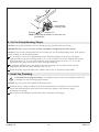
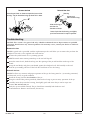
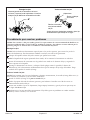
Important Information
WARNING: When using electrical products, basic precautions should always be followed,
including the following:
Building materials and wiring should be routed away from the pump body and other heat-producing
components of the unit.
Install to permit access for servicing.
Grounding is required. The unit should be installed by a qualified service representative, and grounded.
WARNING: Risk of electric shock. A qualified electrician should make all electrical connections.
WARNING: Risk of electric shock. Disconnect power before servicing.
WARNING: Risk of injury or property damage. Please read all instructions thoroughly before
beginning installation, including the following requirements.
NOTICE: Follow all local plumbing and electrical codes.
Product Information
Electrical Requirements
The installation must have a Class A Ground-Fault Circuit-Interrupter (GFCI) or Residual Current Device
(RCD). The GFCI or RCD protects against line-to-ground shock hazard. Use a 120 V, 15 A, 60 Hz dedicated
service for the whirlpool.
″H″ models require a separate 120 V, 15 A, 60 Hz dedicated service for the heater.
NOTE: If the pump supply cord is damaged, it must be replaced by the manufacturer, its service agent or
similarly qualified persons in order to avoid a hazard. The heater supply cord cannot be replaced. If the
cord is damaged the heater should be replaced.
Product Notices
WARNING: Unauthorized modification may cause unsafe operation and poor performance of the
whirlpool. Do not relocate the whirlpool pump, or make other modifications to the whirlpool
system, as this could adversely affect the performance and safe operation of the whirlpool. Kohler
Co. shall not be liable under its warranty or otherwise for personal injury or damage caused by any
such unauthorized modification.
WARNING: Risk of electrical shock. Disconnect power before servicing.
WARNING: Risk of electrical shock. A qualified electrician should make all electrical connections.
WARNING: Risk of injury or property damage. Please read all instructions thoroughly before
beginning installation.
NOTICE: Follow all local plumbing and electrical codes.
Factory-Assembled Features
Factory installed components include pump with power supply cord and air switch transmitter. No
installation is needed.
″H″ models are also supplied with a factory assembled heater.
The whirlpool pump and piping are factory-assembled.
Connections and Service Access
Before installation, ensure proper access to the final connections.
1010564-2-K 2 Kohler Co.

Product Information (cont.)
NOTICE: Provide unrestricted service access to the pump. You must provide access for servicing the
pump and controls. The access must be located immediately next to the pump. Study the Roughing-In
Guide packed with the whirlpool.
Table of Contents
Important Information .............................................................. 2
Product Information ............................................................... 2
Tools and Materials ............................................................... 3
Before You Begin ................................................................. 3
Prepare the Site ................................................................. 4
Prepare the Whirlpool ............................................................. 5
Secure the Unit — Models With Support Blocks .......................................... 5
Secure the Whirlpool to the Stud Framing ............................................... 7
Secure the Unit — Models With Whirlpool Base .......................................... 8
Cut the Pump Banding Straps ...................................................... 10
Install the Plumbing .............................................................. 10
Install a Rim-Mounted Faucet ....................................................... 11
Make Electrical Connections ........................................................ 12
Test Run the Whirlpool ............................................................ 12
Complete the Finished Deck ........................................................ 13
Complete the Finished Wall ........................................................ 14
Clean-Up After Installation ......................................................... 14
Confirm Proper Operation .......................................................... 15
Troubleshooting ................................................................. 16
Tools and Materials
Before You Begin
Inspect the whirlpool for damage before you begin installation.
Confirm adequate mounting and connection space for the faucet specified for your installation.
Kohler Co. reserves the right to make revisions in the design of products without notice, as specified
in the Price Book.
Silicone Sealant
Pencil
Level
Safety Glasses
Tape Measure
Pipe Wrench
Plus:
• Conventional woodworking tools
and materials
• Drop Cloth
• Construction adhesive (optional)
• Cement or mortar (optional)
• 2x4s or 2x6s
• Screws or Lag Bolts
Kohler Co. 3 1010564-2-K

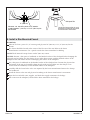
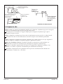
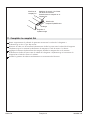
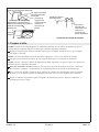
1. Prepare the Site
NOTICE: Refer to the Roughing-in Guide packed with your whirlpool for the required minimum
lb/square foot (kg/square meter) floor support loading.
Make sure the flooring offers adequate support for your whirlpool, and verify that the subfloor is
flat and level.
NOTICE: The whirlpool should be installed in a drop-in, flush, or tiled ledge installation.
Construct 2x4 or 2x6 stud framing designed for your particular installation.
NOTICE: The whirlpool must be supported by its feet or base. Do not support the load weight of the
whirlpool by the perimeter of the rim.
For a raised installation: Frame the floor or construct a frame in accordance with the roughing-in
information packed with the whirlpool.
Carefully lay out and cut the rough deck material. Use the cut-out template, if one is provided, or
refer to the Roughing-In Guide for cutout information.
Position the plumbing according to the roughing-in information packed. Cap the supplies, and
check for leaks.
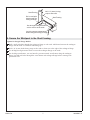
Drop-In Installation
Whirlpool
Rim
Do not support
the whirlpool
by the rim.
Use the roughing-in
information to
construct the stud
framing.
Allow for the thickness of
the planned deck material.
Wood
Batten
Whirlpool
Rim
Flush Installation
Whirlpool
Rim
Use the roughing-in
information to
construct the stud
framing.
Tiled Ledge Installation
1010564-2-K 4 Kohler Co.

2. Prepare the Whirlpool
Install the drain to the whirlpool according to the drain manufacturer’s instructions. Do not connect
the trap at this time.
Position a clean drop cloth or similar material in the bottom of the whirlpool. Be careful not to
scratch the surface of the whirlpool.
3. Secure the Unit — Models With Support Blocks
NOTICE: Do not lift the whirlpool by the piping or pump, or use the piping or pump for structural
support of the whirlpool. To avoid damage to the whirlpool, lift at the sides of the whirlpool.
NOTICE: Do not support the load weight of the whirlpool by the perimeter of the rim. The rim perimeter
must be adequately supported, but must not support the load weight of the whirlpool.
If the subfloor is not level, shim the whirlpool support blocks as necessary.
Choose the installation option that best applies to your particular installation. Follow the appropriate
instructions.
Option Using a Cement or Mortar Bed
NOTE: Do not use gypsum cement or drywall compound for this application, as they will not provide an
acceptable, durable bond.
NOTE: The pump support bracket (when the pump banding straps are cut) and support blocks must
rest directly on the subfloor.
Spread a 2″ (5.1 cm) thick layer of cement or mortar on the subfloor where the whirlpool will be set.
This will help secure, level, and support the unit. Clear all the material away from the pump
support bracket and support block locations.
Position a piece of plastic drop cloth material on top of the cement or mortar bed. With help,
carefully lift the whirlpool into place, and make sure the pump support bracket and support blocks
do not rest in the bed material.
Secure the drain tailpiece to the trap. Ensure the whirlpool is level and resting on all support blocks.
Remove the protective tape from the rim. Apply a continuous bead of high-quality silicone sealant
around the entire rim of the whirlpool.
Option Using Construction Adhesive
Apply a generous amount of high-quality construction adhesive to the bottom of the support blocks.
With help, carefully lift the whirlpool into position.
Frame the floor
according to the
roughing-in information.
Position the rough
plumbing.
Construct 2x4 or 2x6
stud framing according
to the roughing-in
information.
Verify that the subfloor
offers adequate support,
and is flat and level.
Kohler Co. 5 1010564-2-K

Secure the Unit — Models With Support Blocks (cont.)
Insert the drain tailpiece into the trap. Ensure the whirlpool is level and resting on all support
blocks.
Remove the protective tape from the rim. Apply a continuous bead of high-quality silicone sealant
around the entire rim of the whirlpool.
Option Using Silicone Sealant
With help, carefully lift the whirlpool into position.
Insert the drain tailpiece into the trap. Ensure the whirlpool is level and resting on all support
blocks.
Remove the protective tape from the rim. Apply a continuous bead of high-quality silicone sealant
around the entire rim of the whirlpool.
1010564-2-K 6 Kohler Co.

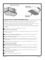
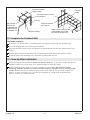
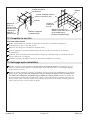
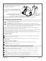
4. Secure the Whirlpool to the Stud Framing
Option for Integral Flange Models
Drill a small pilot hole through the nailing-in flange at each stud. Add shims between the nailing-in
flange and the studs as needed to eliminate gaps.
Nail 1/4” (6 mm) thick furring strips to the studs to shim out to the edge of the nailing-in flange.
Use #6 large-head galvanized nails to secure the nailing-in flange to the studs.
For tile ledge installations, size and install a pressure-treated wood batten along the nailing-in
flange. Pre-drill nail holes through the wood batten and nailing-in flange before securing with
galvanized nails.
Nail 1/4" (6 mm) furring
strips to the studs.
Drill a small pilot
hole through the
nailing-in flange.
Use #6 large-head galvanized
nails to secure to the studs.
Install a pressure-treated wood
batten along the nailing-in flange.
Stud Framing
Stud Framing
Kohler Co. 7 1010564-2-K

5. Secure the Unit — Models With Whirlpool Base
NOTICE: Do not lift the whirlpool by the piping or pump, or use the piping or pump for structural
support of the whirlpool. To avoid damage to the whirlpool, lift at the sides of the whirlpool.
NOTICE: Do not support the load weight of the whirlpool by the perimeter of the rim. The rim perimeter
must be adequately supported, but must not support the load weight of the whirlpool.
Choose the installation option that best applies to your particular installation. Follow the appropriate
instructions.
If the subfloor is not level, shim the whirlpool base as necessary.
Option Using a Cement or Mortar Bed
NOTE: Do not use gypsum cement or drywall compound for this application, as they will not provide an
acceptable, durable bond.
Spread a 2″ (5.1 cm) thick layer of cement or mortar on the subfloor where the whirlpool will be set.
This will help secure, level, and support the unit.
Position a piece of plastic drop cloth material on top of the cement or mortar bed. With help,
carefully lift the whirlpool into place.
Insert the drain tailpiece into the trap. Make sure the whirlpool is level. Use screws or lag bolts (not
provided) to secure the whirlpool base to the floor. Drill small pilot holes through the whirlpool
base as needed.
Remove the protective tape from the rim. Apply a continuous bead of high-quality silicone sealant
around the entire rim of the whirlpool.
Option Using Construction Adhesive
Apply a generous amount of high-quality construction adhesive to the bottom of the whirlpool base.
With help, carefully lift the whirlpool into position.
Insert the drain tailpiece into the trap. Make sure the whirlpool is level. Use screws or lag bolts (not
provided) to secure the whirlpool base to the floor. Drill small pilot holes through the whirlpool
base as needed.
Remove the protective tape from the rim. Apply a continuous bead of high-quality silicone sealant
around the entire rim of the whirlpool.
Option Using Silicone Sealant
With help, carefully lift the whirlpool into position.
Spread a 2" (5.1 cm) layer of
cement or mortar bed material.
Apply construction
adhesive to the
whirlpool base.
Apply a bead of
silicone sealant
around the entire rim.
1010564-2-K 8 Kohler Co.

Secure the Unit — Models With Whirlpool Base (cont.)
Insert the drain tailpiece into the trap. Make sure the whirlpool is level. Use screws or lag bolts to
secure the whirlpool base to the floor. Drill small pilot holes through the whirlpool base as needed.
Remove the protective tape from the rim. Apply a continuous bead of high-quality silicone sealant
around the entire rim of the whirlpool.
Kohler Co. 9 1010564-2-K

6. Cut the Pump Banding Straps
NOTE: If your pump model does not have banding straps, proceed to the next section.
IMPORTANT! This step is necessary to make your Kohler whirlpool operate more quietly.
NOTE: Do not raise the pump higher than it was before you cut the pump banding straps. If the pump is
raised too high, it will not prime properly.
Use tin snips to cut the two pump banding straps. When the banding straps are cut, the pump
support bracket and pump will drop about 1/2″ (1.3 cm) until they rest on the subfloor. If the pump
drops more than 1/2″ (1.3 cm), shim under the pump support bracket so there is a 1/2″ (1.3 cm)
gap between the pump and bracket to allow for proper drainage.
To minimize whirlpool noise and vibration, be sure the pump is not in direct contact with the
shipping bracket after the pump banding straps are cut.
Secure the pump support bracket to the subfloor with screws or lag bolts (not provided).
7. Install the Plumbing
CAUTION: Risk of property damage. A watertight seal must exist on the whirlpool drain. The
watertight seal will prevent property damage.
NOTICE: An access panel will simplify future maintenance.
Install the faucet valving according to the faucet manufacturer’s instructions. Do not install the
faucet trim until instructed. Open the hot and cold water supplies, and check the supply
connections for leakage.
Run water into the whirlpool, and check the drain connections for leakage.
Drainage
Suction Line
Pump
Cut the pump
banding straps.
NOTE:
Pump model illustrated may differ from your
actual product.
1010564-2-K 10 Kohler Co.

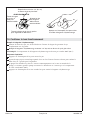
8. Install a Rim-Mounted Faucet
K-1226 Only
Measure and cut a piece of 1/2″ exterior grade plywood 4″ (10.2 cm) x 11-1/2″ (29.2 cm) for the
K-1226.
The faucet should be located in the center of the flat area of the rim. Refer to the faucet
manufacturer’s instructions. Use a pencil to mark the faucet centerlines for drilling.
NOTE: The K-1226 will accept faucets with 4″ (10.2 cm) centers.
NOTICE: Position a thin piece of cardboard on the finished surface of the whirlpool before clamping the
plywood in place. Make sure the clamps do not make direct contact with the finished surface of the
whirlpool. This will reduce the risk of damaging the surface of the whirlpool.
Set a thin piece of cardboard on the finished surface of the whirlpool rim. Position the plywood on
the bottom of the rim, and carefully clamp the plywood in place. Make sure the clamps are in
contact with the cardboard, not the finished surface of the whirlpool.
Carefully drill the faucet holes to the size required by the faucet manufacturer. Remove the clamps
and cardboard.
Install the faucet to the rim and plywood according to the faucet manufacturer’s instructions.
Open the hot and cold water supplies, and check the supply connections for leakage.
Run water into the whirlpool, and check the drain connections for leakage.
4" (10.2 cm)
Measure, cut, and drill a piece of 1/2" exterior
grade plywood 4" (10.2 cm) x 11-1/2" (29.2 cm) for
the K-1226.
Whirlpool Rim
Install the faucet to the rim and
plywood according to the faucet
manufacturer's instructions.
Kohler Co. 11 1010564-2-K

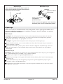
9. Make Electrical Connections
WARNING: Risk of electric shock. Make sure the power has been disconnected before performing
the following procedures.
WARNING: Risk of electric shock. Connect the pump and in-line heater (if included) to properly
grounded, grounding-type receptacles protected by Ground-Fault Circuit-Interrupters (GFCI’s) or
Residual Current Devices (RCD’s). Do not remove the grounding pins from the plug. Do not use
grounding adapters.
NOTE: A label identifying the model number and electrical rating of the whirlpool is located near the
whirlpool pump.
NOTICE: The pump (supplied) and heater (if supplied) are equipped with a cord and plug. All wiring for
the heater has been completed at the factory. A qualified electrician must install a GFCI- or RCD-protected,
120 V, 15 A, grounded outlet. No other load should be on this circuit.
Pump Wiring
Locate the outlet behind the whirlpool, and within 24″ (61 cm) of the pump.
Plug the pump into this outlet.
NOTE: Make sure the air actuator tubing is securely attached to the pump, and is not kinked or damaged.
Heater Wiring – “H” Models
Locate the outlet behind the whirlpool, and within 24″ (61 cm) of the heater.
Plug the heater into this outlet.
10. Test Run the Whirlpool
Check all electrical connections, and make sure the electrical power to the whirlpool and heater (if
equipped) is on.
Make sure all union connections to the pump and heater are securely hand tightened.
Verify that the pump banding straps have been cut (if applicable), and that the pump is resting
directly on the subfloor or whirlpool base.
Fill the whirlpool to a level at least 2″ (5.1 cm) above the top of the highest jet. Refer to ″Confirm
Proper Operation″ section for additional information.
Operate the whirlpool for 5 minutes, and check all whirlpool piping connections for leaks.
NOTE:
Pump model illustrated may differ from your actual product.
Install a GFCI- or RCD-protected 120 V, 15 A grounded outlet. Install a second GFCI-
or RCD-protected outlet for "H" models for the heater.
Make sure air actuator tubing is securely
attached to the pump.
Optional Heater
(models may vary)
either T-style (shown) or water intake
(not shown).
Bond in accordance with applicable codes.
Plug pump and heater
into these outlets.
1010564-2-K 12 Kohler Co.

11. Complete the Finished Deck
If you have not already done so, carefully remove the protective tape from the whirlpool rim.
Cover the framing with water-resistant deck material. Seal the joints between the whirlpool rim
edge and the water-resistant deck material with silicone sealant.
Tape and mud the water-resistant deck material. Install the finished deck to the water-resistant deck
material. Seal the joints between the whirlpool rim and the finished deck material with silicone
sealant.
Install the faucet trim according to the trim manufacturer’s instructions.
Whirlpool
Framing
Water-Resistant
Deck Material
Apply silicone sealant to the
edges of the water-resistant
deck material and the
finished deck
Finished Deck
Material
Kohler Co. 13 1010564-2-K

12. Complete the Finished Wall
Tiled Ledge Installation
If you have not already done so, carefully remove the protective tape from the whirlpool rim.
Cover the framing with water-resistant wall material.
Tape and mud the water-resistant wall material. Install the finished wall to the water-resistant wall
material.
Seal the joints between the whirlpool rim and the finished wall material with silicone sealant.
Install the faucet trim according to the instructions packed with the trim.
13. Clean-Up After Installation
When cleaning up after installation, do not use abrasive cleansers, as they may scratch and dull the
whirlpool surface. Use warm water and a liquid detergent to clean the surface.
Remove stubborn stains, paint, or tar with turpentine or paint thinner. Do not allow cleaners
containing petroleum distillates to remain in contact with any whirlpool surfaces for long periods
of time. Remove plaster by carefully scraping with a wood edge. Do not use metal scrapers, wire
brushes, or other metal tools. Use a powder-type detergent on a damp cloth to provide mild
abrasive action to any residual plaster.
Apply silicone
sealant to the
joint between the
finished wall and
the whirlpool rim.
Install the finished
ledge material.
First install water-resistant
wall material.
Install the finished
wall material.
Apply silicone sealant to the
joint between the finished
wall and the whirlpool rim.
Finished
Ledge
Whirlpool Flange
Framing
1010564-2-K 14 Kohler Co.

14. Confirm Proper Operation
Fill the Whirlpool
Position the jet nozzles so they face down toward the basin. Turn the jet trim rings fully
counterclockwise.
Fill the whirlpool to a water level at least 2″ (5.1 cm) above the top of the highest jet.
NOTE: The water temperature in the whirlpool should not exceed 104°F (40°C).
Operating Sequence
Press the air actuator to turn on the whirlpool jets.
Adjust each jet for optimum air/water mixture. Turn the trim ring clockwise to reduce the air flow,
and counterclockwise to increase the air flow.
If equipped with a heater, the heater will engage automatically when the pump is turned on and
will disengage when the pump is turned off. The heater will not turn on if the water temperature
exceeds 104°F (40°C).
Press the air actuator a second time to turn off the whirlpool.
Fill with water at least 2" (5.1 cm)
above the highest jet.
Turn the jet trim ring
clockwise to
decrease the flow.
Position the jet
nozzles to direct
the water flow as
desired.
Turn the jet trim ring counterclockwise
to increase the flow.
Press the air actuator to turn
on and off the whirlpool.
Kohler Co. 15 1010564-2-K

Troubleshooting
NOTICE: This section is for general aid only. A Kohler Authorized Service Representative or qualified
electrician should correct any electrical problems. For warranty service, contact your dealer or wholesale
distributor.
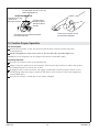
Remove the Jets
NOTE: A special tool is provided with the replacement jets that will allow you to remove the jets from the
whirlpool. This tool is also supplied with each trim kit.
Position the jet ball nozzle so it is pointing upward.
NOTE: The nozzle must remain pointed up or the tool will slip off.
Insert the removal tool, hooked end up, into the opening of the jet and hook the inside top of the
nozzle.
Grasp the tool firmly and place your thumb against the whirlpool wall. Pull steadily on the tool
until the jet assembly pulls free of the hole. Be careful not to lose the O-ring.
Reinstall the Jets
NOTE: To allow easy rotation and proper operation of the jet, the O-ring must be: (1) correctly positioned,
(2) lubricated, and (3) in good condition.
Install the O-ring onto the first shoulder of the jet.
Using the silicone lube packet (provided), lubricate the O-ring to prevent noisy operation of the jet.
Carefully insert the jet into the housing, then lightly push and rotate the jet until it snaps into
position. Do not force the jet.
Verify the jet is installed correctly. The jet should turn smoothly both clockwise and
counterclockwise. Remove and reinstall, if necessary.
Remove the Jets
Insert the tool hook as shown and pull the jet out of the
housing. The jet should be facing up when this is done.
Housing
Reinstall the Jets
Insert the jet into the housing, and lightly
push and rotate until it snaps in position.
Inspect and
lubricate the O-ring.
Slide the O-ring
onto the first
shoulder of the jet.
1010564-2-K 16 Kohler Co.

Troubleshooting (cont.)
Symptoms Probable Causes Recommended Action
1. Whirlpool
will not
start/stop.
A. No power to pump. A. Verify pump is plugged in and the
GFCI/RCD is not tripped. Verify the
outlet has power using a multi-meter or
by connecting a 110V item that you know
is working (lamp, radio, etc.) into the
outlet. Repair as needed.
B. Remove the access panel and press
the air switch, if you do not hear a
″click,″ the air switch tubing is loose
or disconnected.
B. Check if the air switch tubing is connected
at both the receiver/pump end and the air
switch. Reconnect if needed.
C. Air switch tubing is pinched or
kinked.
C. Adjust tubing to clear the pinched/kinked
area. If the pinch/kink cannot be fixed, or
no noticeable pinch/kink is apparent,
puncture the tubing with a tack and try
the system again.
D. Push button assembly is damaged. D. Replace the push button assembly.
E. Pump has power and a ″click″ is
heard when the air switch is pressed.
Pump is not operating.
E. Replace the pump.
F. The receiver in the pump is not
operating.
F. Replace the receiver or pump.
2. The system
will start but
will not stay
ON.
A. The receiver in the pump is not
operating.
A. Replace the receiver or pump.
3. Whirlpool
stops
automatically.
A. Pump has overheated and the
protection devices have activated.
A. Check for blockage at the motor vents.
Check for suction blockage. Check for jet
blockage. Remove any blockage and allow
the motor to cool.
B. GFCI/RCD circuit has tripped. B. Identify source fault and correct. Check
that the GFCI/RCD has not been tripped.
If problem persists, contact a qualified
electrician.
4. The motor
starts but not
all jets
function.
A. Jets are closed. A. Rotate the jet trim ring counterclockwise
to open/increase flow to the jets.
B. Jets are blocked or trim ring rotation
is impeded.
B. Glue may be obstructing the jet opening
or preventing the jet trim ring from
rotating. Remove the trim ring and
remove excess glue.
C. Jets not installed correctly. C. Reinstall the jet; check for any O-ring
damage.
D. Pump is not supported correctly and
is cavitating.
D. Review the installation instructions and
verify that the pump is at the appropriate
height and that the pump banding straps
(when applicable) have been cut.
5. Noisy pump
operation.
A. The pump banding straps have not
been cut (models with support blocks
only).
A. Using tin snips, cut pump banding straps.
6. Heater does
not operate
(units with
heaters only).
A. No power to heater or it is not
connected to a separate outlet from
the pump.
A. Verify that the heater is connected to a
separate outlet from the pump and that
the connection has power.
B. The water temperature is above 104°F
(40°C).
B. As a safety precaution, the heater will not
operate when the water temperature is
above 104°F (40°C).
Kohler Co. 17 1010564-2-K
Page is loading ...
Page is loading ...
Page is loading ...
Page is loading ...
Page is loading ...
Page is loading ...
Page is loading ...
Page is loading ...
Page is loading ...
Page is loading ...
Page is loading ...
Page is loading ...
Page is loading ...
Page is loading ...
Page is loading ...
Page is loading ...
Page is loading ...
Page is loading ...
Page is loading ...
Page is loading ...
Page is loading ...
Page is loading ...
Page is loading ...
Page is loading ...
Page is loading ...
Page is loading ...
Page is loading ...
Page is loading ...
Page is loading ...
Page is loading ...
Page is loading ...
Page is loading ...
Page is loading ...
Page is loading ...
Page is loading ...
Page is loading ...
Page is loading ...
Page is loading ...
Page is loading ...
-
 1
1
-
 2
2
-
 3
3
-
 4
4
-
 5
5
-
 6
6
-
 7
7
-
 8
8
-
 9
9
-
 10
10
-
 11
11
-
 12
12
-
 13
13
-
 14
14
-
 15
15
-
 16
16
-
 17
17
-
 18
18
-
 19
19
-
 20
20
-
 21
21
-
 22
22
-
 23
23
-
 24
24
-
 25
25
-
 26
26
-
 27
27
-
 28
28
-
 29
29
-
 30
30
-
 31
31
-
 32
32
-
 33
33
-
 34
34
-
 35
35
-
 36
36
-
 37
37
-
 38
38
-
 39
39
-
 40
40
-
 41
41
-
 42
42
-
 43
43
-
 44
44
-
 45
45
-
 46
46
-
 47
47
-
 48
48
-
 49
49
-
 50
50
-
 51
51
-
 52
52
-
 53
53
-
 54
54
-
 55
55
-
 56
56


Ask a question and I''ll find the answer in the document
Finding information in a document is now easier with AI
in other languages
- français: Kohler K-1154-HC-47 Guide d'installation
- español: Kohler K-1154-HC-47 Guía de instalación
Related papers
-
Kohler K-1124-95 Installation guide
-
Kohler K-1162-0 Installation guide
-
Kohler K-1242-R-0 Installation guide
-
-
Kohler K-1257-HL-0 Installation guide
-
-
-
Kohler K-716-47 Installation guide
-
-
Other documents
-
Sterling 76261110-96 Installation guide
-
-
Westbrass D400-1-50 Installation guide
-
-
 Bathcraft A97242CWWH Installation guide
-
-
Sioux Chief 886-411 Installation guide
-
-
Jacuzzi Espree 6036 User manual
-
