Page is loading ...

bus
CT-100C SERIES
SIX-SLOT VXIBUS CHASSIS
USER’S
M
ANUAL
P/N: 82-0102-000
Released November 16, 2007
VXI Technology, Inc.
2031 Main Street
Irvine, CA 92614-6509
(949) 955-1894

VXI Technology, Inc.
2

www.vxitech.com
CT-100C Preface 3
TABLE OF CONTENTS
INTRODUCTION
Table of Contents......................................................................................................................................................3
Certification .........................................................................................................................................................4
Warranty ..............................................................................................................................................................4
Limitation of Warranty ........................................................................................................................................4
Restricted Rights Legend.....................................................................................................................................4
Declaration of Conformity........................................................................................................................................5
General Safety Instructions.......................................................................................................................................6
Terms and Symbols..............................................................................................................................................6
Warnings..............................................................................................................................................................6
Support Resources....................................................................................................................................................8
SECTION 1 .................................................................................................................................................................. 11
Introduction ............................................................................................................................................................11
Introduction........................................................................................................................................................11
General Description ...........................................................................................................................................12
Backplane...........................................................................................................................................................12
Performance.......................................................................................................................................................12
Flexibility...........................................................................................................................................................13
CT-100C Mainframe Features...........................................................................................................................14
Voltage Monitor LEDs ......................................................................................................................................15
CT-100C Specifications.....................................................................................................................................17
SECTION 2 .................................................................................................................................................................. 21
Installation ..............................................................................................................................................................21
Introduction........................................................................................................................................................21
Backplane...........................................................................................................................................................21
Remote Power-On Option..................................................................................................................................22
+5 V Standby Usage ..........................................................................................................................................23
Fan Speed Switch...............................................................................................................................................24
Rackmount Option Installation...............................................................................................................................25
Overview............................................................................................................................................................25
Rackmount Kit Installation.....................................................................................................................................26
Rack Slide Installation (20” and 24”).....................................................................................................................28
Rackmount Door Kit Installation............................................................................................................................30
Acrylic Rackmount Door Kit Installation...............................................................................................................32
Installation of VXI Modules...................................................................................................................................34
Overview............................................................................................................................................................34
Disconnecting the Mainframe.................................................................................................................................35
SECTION 3 .................................................................................................................................................................. 37
Service Information................................................................................................................................................37
Introduction........................................................................................................................................................37
Replicable Parts List ..........................................................................................................................................37
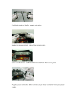
CT-100C Power Supply Replacement...............................................................................................................38
Cleaning the Mainframe.....................................................................................................................................40
INDEX ......................................................................................................................................................................... 41

VXI Technology, Inc.
4 CT-100C Preface
CERTIFICATION
VXI Technology, Inc. (VTI) certifies that this product met its published specifications at the time of shipment from
the factory. VTI further certifies that its calibration measurements are traceable to the United States National
Institute of Standards and Technology (formerly National Bureau of Standards), to the extent allowed by that
organization’s calibration facility, and to the calibration facilities of other International Standards Organization
members.
WARRANTY
The product referred to herein is warranted against defects in material and workmanship for a period of three years
from the receipt date of the product at customer’s facility. The same warranty applies to the power supply for a
period of one year. The sole and exclusive remedy for breach of any warranty concerning these goods shall be
repair or replacement of defective parts, or a refund of the purchase price, to be determined at the option of VTI.
For warranty service or repair, this product must be returned to a VXI Technology authorized service center. The
product shall be shipped prepaid to VTI and VTI shall prepay all returns of the product to the buyer. However, the
buyer shall pay all shipping charges, duties, and taxes for products returned to VTI from another country.
VTI warrants that its software and firmware designated by VTI for use with a product will execute its programming
when properly installed on that product. VTI does not however warrant that the operation of the product, or
software, or firmware will be uninterrupted or error free.
LIMITATION OF WARRANTY
The warranty shall not apply to defects resulting from improper or inadequate maintenance by the buyer, buyer-
supplied products or interfacing, unauthorized modification or misuse, operation outside the environmental
specifications for the product, or improper site preparation or maintenance.
VXI Technology, Inc. shall not be liable for injury to property other than the goods themselves. Other than the
limited warranty stated above, VXI Technology, Inc. makes no other warranties, express or implied, with respect to
the quality of product beyond the description of the goods on the face of the contract. VTI specifically disclaims the
implied warranties of merchantability and fitness for a particular purpose.
RESTRICTED RIGHTS LEGEND
Use, duplication, or disclosure by the Government is subject to restrictions as set forth in subdivision (b)(3)(ii) of
the Rights in Technical Data and Computer Software clause in DFARS 252.227-7013.
VXI Technology, Inc.
2031 Main Street
Irvine, CA 92614-6509 U.S.A.

www.vxitech.com
CT-100C Preface 5
D ECLARATION OF C ONFORMITY
Declaration of Conformity According to ISO/IEC Guide 22 and EN 45014
M
ANUFACTURER’S NAME VXI Technology, Inc.
M
ANUFACTURER’S ADDRESS 2031 Main Street
Irvine, California 92614-6509
P
RODUCT NAME Six-Slot VXIbus Chassis
M
ODEL NUMBER(S) CT-100C
P
RODUCT OPTIONS All
P
RODUCT CONFIGURATIONS All
VXI Technology, Inc. declares that the aforementioned product conforms to the requirements of
the Low Voltage Directive 73/23/EEC and the EMC Directive 89/366/EEC (inclusive 93/68/EEC)
and carries the “CE” mark accordingly. The product has been designed and manufactured
according to the following specifications:
S
AFETY EN61010 (2001)
EMC EN61326 (1997 w/A1:98) Class A
CISPR 22 (1997) Class A
VCCI (April 2000) Class A
ICES-003 Class A (ANSI C63.4 1992)
AS/NZS 3548 (w/A1 & A2:97) Class A
FCC Part 15 Subpart B Class A
EN 61010-1:2001
I hereby declare that the aforementioned product has been designed to be in compliance with the relevant sections
of the specifications listed above as well as complying with all essential requirements of the Low Voltage Directive.
November 2007
Steve Mauga, QA Manager

VXI Technology, Inc.
6 CT-100C Preface
GENERAL SAFETY INSTRUCTIONS
Review the following safety precautions to avoid bodily injury and/or damage to the product.
These precautions must be observed during all phases of operation or service of this product.
Failure to comply with these precautions, or with specific warnings elsewhere in this manual,
violates safety standards of design, manufacture, and intended use of the product.
Service should only be performed by qualified personnel.
TERMS AND SYMBOLS
These terms may appear in this manual:
WARNING
Indicates that a procedure or condition may cause bodily injury or death.
CAUTION
Indicates that a procedure or condition could possibly cause damage to
equipment or loss of data.
These symbols may appear on the product:
ATTENTION - Important safety instructions
Frame or chassis ground
Indicates that the product was manufactured after August 13, 2005. This mark is
placed in accordance with EN 50419, Marking of electrical and electronic
equipment in accordance with Article 11(2) of Directive 2002/96/EC (WEEE).
End-of-life product can be returned to VTI by obtaining an RMA number. Fees
for take-back and recycling will apply if not prohibited by national law.
WARNINGS
Follow these precautions to avoid injury or damage to the product:
Use Proper Power Cord
To avoid hazard, only use the power cord specified for this product.
Use Proper Power Source
To avoid electrical overload, electric shock, or fire hazard, do not
use a power source that applies other than the specified voltage.

www.vxitech.com
CT-100C Preface 7
WARNINGS (CONT.)
Avoid Electric Shock
To avoid electric shock or fire hazard, do not operate this product
with the covers removed. Do not connect or disconnect any cable,
probes, test leads, etc. while they are connected to a voltage source.
Remove all power and unplug unit before performing any service.
Service should only be performed by qualified personnel.
Ground the Product
This product is grounded through the grounding conductor of the
power cord. To avoid electric shock, the grounding conductor must
be connected to earth ground.
Operating Conditions
To avoid injury, electric shock or fire hazard:
- Do not operate in wet or damp conditions.
- Do not operate in an explosive atmosphere.
- Operate or store only in specified temperature range.
- Provide proper clearance for product ventilation to prevent
overheating.
- DO NOT operate if any damage to this product is suspected.
Product should be inspected or serviced only by qualified
personnel.
Improper Use
The operator of this instrument is advised that if equipment is
used in a manner not specified in this manual, the protection
provided by this equipment be may be impaired.

VXI Technology, Inc.
8 CT-100C Preface
SUPPORT RESOURCES
Support resources for this product are available on the Internet and at VXI Technology customer
support centers.
VXI Technology
World Headquarters
VXI Technology, Inc.
2031 Main Street
Irvine, CA 92614-6509
Phone: (949) 955-1894
Fax: (949) 955-3041
VXI Technology
Cleveland Instrument Division
VXI Technology, Inc.
7525 Granger Road, Unit 7
Valley View, OH 44125
Phone: (216) 447-8950
Fax: (216) 447-8951
VXI Technology
Lake Stevens Instrument Division
VXI Technology, Inc.
1924 - 203 Bickford
Snohomish, WA 98290
Phone: (425) 212-2285
Fax: (425) 212-2289
Technical Support
Phone: (949) 955-1894
Fax: (949) 955-3041
E-mail:
Visit
http://www.vxitech.com for worldwide support sites and service plan information.

www.vxitech.com
CT-100C Preface 9

www.vxitech.com
CT-100C Introduction 11
SECTION 1
INTRODUCTION
INTRODUCTION
The CT-100C portable C-size VXIbus mainframe provides cost-effective test situations in a small
footprint. When using VMIP™ instruments such as DMMs, waveform generators, digitizers, etc.,
complete test scenarios can easily be configured.
FIGURE 1-1: CT-100C SIX SLOT CHASSIS

VXI Technology, Inc.
12 CT-100C Introduction
GENERAL DESCRIPTION
The CT-100C chassis is a portable, C-size, six-slot, VXIbus compatible chassis that conforms
fully to VXIbus Specification Revision 2.0. The chassis employs a multi-layer backplane to
ensure premium VXIbus and VMEbus performance and provides all power supplies required by
the VXIbus specification.
The CT-100C supports conventional existing rack designs through an optional rackmounting kit
(see
Section 1). The six-slot design minimizes the use of precious rack space and is an economical
alternative to a larger chassis when fewer slots are required.
The CT-100C chassis contains six slots in the card cage, five of which are available for use by
VXIbus compatible instruments. The sixth slot in the card cage (slot 0) is typically dedicated to
the VXIbus Resource Manager.
The CT-100C is designed to operate at line frequencies between 47 Hz and 63 Hz and utilizes a
power supply that automatically adjusts to accept line voltages between 100 V ac and 240 V ac.
There is an internal fuse that provides protection against catastrophic failures and is designed to
operate within the valid input range.
The rear panel provides a connector for 5V STANDBY. Power supplied to this connector is
passed directly to the backplane line +5V STDBY. This allows properly configured systems to
take advantage of an alternate power supply source, i.e., battery backup of memory or energizing
high stability reference oscillators.
BACKPLANE
The backplane is a monolithic, multi-layer design, with automatic, solid-state daisy-chain
jumpering for the interrupt acknowledge and VMEbus grant lines. This eliminates the need for
manual jumpering and provides improved reliability over mechanical jumper-less backplane
designs. Instrument modules can now be added or removed without concern for the backplane
configuration.
PERFORMANCE
The CT-100C uses a pressurized airflow system. As air enters the mainframe from the rear, it is
pressurized below the cards and is then evenly distributed across all slots and along the total
length of each card slot, avoiding hot spots common in other designs. The air exhausts through the
top and away from the user. This cooling approach helps increase MTBF (Mean Time Before
Failure) figures and module performance.
High-quality power supplies are used in the CT-100C that are UL, CSA, and TUV approved. The
power supplies are short-circuit, over-voltage, reverse-voltage and thermal-shutdown protected.
Auto-ranging power supplies are used to avoid any concern about the voltage source used. In
addition, all supply lines are monitored and displayed on the front panel to provide user feedback
of correct operation (see
Figure 1-4).

www.vxitech.com
CT-100C Introduction 13
FLEXIBILITY
The CT-100C is designed to provide flexibility of use in bench-top and rackmount applications, as
well as in portable environments. The outside cover is removable for easy access to the VXIbus
modules during bench-top development, troubleshooting, or calibration. For rackmount
applications, a rackmount kit allows the CT-100C to mount flush or be recessed four inches. A
latched door is provided with the rackmount kit, which can be user-modified to accept connectors,
switches, or indicators. See
Section 1 for rackmount installation.
FIGURE 1-2: CT-100C SIX-SLOT CHASSIS – COVERS OFF

VXI Technology, Inc.
14 CT-100C Introduction
CT-100C MAINFRAME FEATURES
FRONT PANEL FEATURES
POWER SWITCH
Feature 1
When elevated, the mainframe is in standby mode, where power is supplied to the
mainframe, but not to the VXI modules.
When depressed, power is supplied to both mainframe and VXI modules
VOLTAGE INDICATORS
Feature 2
Indicates whether specific backplane voltages are within specifications. See
Figure 1-4
for details.
FAN INDICATOR
Feature 3
Indicates whether the fan voltages are within specifications. See
Figure 1-4 for details.
REAR PANEL FEATURES
FAN SPEED SWITCH
Feature 4
Enables the user to vary the speed of the fan between HIGH and LOW. See
Figure 1-3
for details.
J200 CONNECTOR
Feature 5
AC power receptacle.
GROUND STUD
Feature 6
Used to electrical ground the mainframe.
J201 CONNECTOR
Feature 7
See
Figure 1-5 and Table 1-1 for connector pin assignments.
VXI Technology
FAN SPEED
HIGH / LOW
J201
MONITOR / CONTROL
100-240 VAC
10A MAX.
47 - 63 Hz
J200
WARNING - TO PREVENT POSSIBLE ELECTRIC SHOCK HAZARD, DISCONNECT POWER
CORD BEFORE REMOVING THE POW ER SUPPLY M ODULE FROM THE MAINFRAME.
ATTENTION - POUR EMP Ê CHER LE RISQUE POSSIBLE DE D É CHARGE É LECTRIQUE,
DEBRANCHER LE CORDON DE SECTEUR AVANT D'ENLEVER LE MODULE
D'ALIMENTATION D' É NERGIE DE L'UNIT É CENTRALE.
WARNING - FOR PROTECTION FROM ELECTRIC SHOCK, THE GROUNDING CONNECTION
IN THE POWER CORD MUST BE PROPERLY CONNECTED.
ATTENTION - POUR LA PROTECTION CONTRE LE CHOC É LECTRIQUE , LA PRISE DE
TERRE AU SOL DANS LE CORDON DE SECTEUR DOIT Ê TRE CORRECTMENT RELI É E.
WARNING - NO OPERATOR SERVICEABLE PARTS INSIDE. REFER SERVICING TO
TRAINED SERVICE PERSONNEL.
ATTENTION - AUCUNES PI È CES REPARABLES PAR UN OP É RATEUR À L'INT É RIEUR.
R É F É REZ L'ENTRETIEN AU PERSONNEL QUALIFI É.
!
!
!
0 1 2 3 4 5
Voltage Monitor s Pow er
+5V +12V +24V +5V Stby
-5.2V -12V -24V -2V FAN
CT-100C
VXI Mainframe
12
3
4
5
6
7
FIGURE 1-3: MAINFRAME FEATURE LOCATIONS

www.vxitech.com
CT-100C Introduction 15
VOLTAGE MONITOR LEDS
The power supply lines are monitored and displayed on the front panel, providing information
pertaining to the chassis operational status.
0 1 2 3 4 5
V
oltage Monitors Power
+5V +12V +24V +5V Stby
-5.2V -12V -24V -2V FAN
CT-100C
VXI Mainframe
Voltage Monitor LEDs
Green : Within Voltage Specifications
: Under Voltage Specifications
: Over Voltage Specifications
Not Lit
Red
FAN LEDs
*Note: +5 V Stby is lit only when the +5 V is supplied by the
user to the + 5 V Stby pins (pins 8 & 12) of the monitor
connector located on the rear panel.
Green : Within Voltage Specifications
: Under Voltage Specifications
: Over Voltage Specifications
Not Lit
Red
NOTE At power up, the voltage monitor LED may blink for the first several seconds if the fan speed is
set to “HIGH”.
FIGURE 1-4: FRONT PANEL VOLTAGE MONITORS

VXI Technology, Inc.
16 CT-100C Introduction
TABLE 1-1: J201 CONNECTOR PIN ASSIGNMENTS
Pin Number Description
1 +5 V Monitor
†
2 -12 V Monitor
†
3 -24 V Monitor
†
4 -2 V Monitor
†
5 Remote Power Switch
6 +5 V Output
‡
7 +12 V Output
‡
8 +5 V Standby Input
9 Ground
10 Backplane Reset I/O
11 N/C
12 N/C
13 Fan OK Output
14 +12 V Monitor
†
15 +24 V Monitor
†
16 -5.2 V Monitor
†
17 Ground
18 Remote Power Switch Return
19 Ground
20 Ground
21 +5 V Standby
22 Ground
23 AC Fail I/O
24 Ground
25 N/C
NOTE Monitor lines function as outputs only.
‡
Pin 6 and Pin 7 (+5 V Output and +12 V Output, respectively) can provide 0.5 A from the
power supply.
Both jackscrews connect to ground.
Pin 13
Pin 1
Pin 25
Pin 14
FIGURE 1-5: J201 CONNECTOR PIN DETAIL

www.vxitech.com
CT-100C Introduction 17
CT-100C SPECIFICATIONS
GENERAL SPECIFICATIONS
SIZE
6.96" (176.78 mm) W x 15.00" (381.00 mm) H x 21.3" D (541.02 mm)
Six C-size VXIbus card slots (see
Figure 1-6 for details)
WEIGHT
22 lb / 10 kg
VXIBUS VERSION
2.0
MTBF
100,000 hr
MTTR
5 min
ENVIRONMENTAL SPECIFICATIONS
OPERATING LOCATION
This chassis should be operated indoors in a controlled environment, protected
from exposure to the elements (i.e. direct sunlight, precipitation, wind, etc.).
Pollution degree 2. Installation Category II.
TEMPERATURE
Operating
Storage
0 °C to +55 °C
-40 °C to +70 °C
HUMIDITY
Operating
Non-operating
Up to 95% (non-condensing) at up to 30 °C; up to 45% at up to 55 °C
Up to 95% (non-condensing) at up to 55 °C
ALTITUDE
Operating
Non-operating
15,000 ft (4,570 m)
40,000 ft (12,190 m)
RANDOM VIBRATION*
Operating
Non-operating
0.27 g-rms total from 5 Hz to 55 Hz
2.28 g-rms total from 5 Hz to 55 Hz
* Three axis, 30 min total, 10 min per axis.
FUNCTIONAL SHOCK
Operating
Half sine, 30 g, 11 ms duration
Meets functional shock requirements of MIL-T-28800E, Type III, Class 5

VXI Technology, Inc.
18 CT-100C Introduction
POWER SPECIFICATIONS
USEABLE POWER
500 W to 50 °C, derated by 2.5%/ °C above 50 °C
DC SUPPLY VOLTAGE
Voltage
Peak
Current
(I
MP
)
Dynamic
Current
(I
MD
) Allowed Variation
Ripple/Noise
DC Load
Induced
Ripple
Noise
+5 V 40 A 5 A +0.25 V / -0.125 V 50 mV 50 mV
-5.2 V 10 A 5 A -0.26 V / +0.125 V 50 mV 50 mV
-2 V 8 A 2 A -0.10 V / +0.72 V 50 mV 50 mV
+12 V 8 A 2 A +0.60 V / -0.36 V 50 mV 50 mV
-12 V 4 A 2 A -0.60 V / +0.36 V 50 mV 50 mV
+24 V 4 A 2 A +1.20 V / -0.72 V 150 mV 150 mV
-24 V 4 A 2 A -1.20 V / +0.74 V 150 mV 150 mV
POWER INPUT
Input Voltage / Freq.
Nominal AC
Inrush Current
Input Power
Input Leakage
Input Harmonics
Fuse
Minimum 100 V ac to a maximum 240 V ac, 50 Hz/60 Hz
< 40 A (cold start)
10 A max
< 1.24 MA @ 264 V ac, 53 Hz
Meets EN61000-3-2
Internal and independent of line voltage (not user accessible)
POWER SUPPLIES
UL, CSA, TUV approved, CE marked
Shout circuit, over-voltage, reverse voltage and thermal shutdown protection
COOLING SPECIFICATIONS
COOLING REQUIREMENTS*
Low Fan Speed
High Fan Speed
56 W/slot for a 10°C Rise
84 W/slot for a 15°C Rise
80 W/slot for a 10°C Rise
120 W/slot for a 15°C Rise
*Calculated using VXI-8 Rev. 2.0 standards
COOLING MODES
High or low speed cooling modes can be selected by moving the Fan Speed
switch at the rear of the chassis. The power supply and modules are cooled by
separate fans.
AIR FLOW PATH
Air is drawn into the chassis from the rear and is pressurized below the cards.
The air is then distributed across all slots along the total length of each slot and
is exhausted through the top of the mainframe. When the mainframe is rack
mounted, allow approximately 2 inches (50 mm) of clearance at the top and rear
for proper airflow.
ACOUSTIC NOISE
High Speed Fan Mode < 40 dBA
Low Speed Fan Mode < 30 dBA

www.vxitech.com
CT-100C Introduction 19
* Covers all slots, unrestricted
0.0
1.0
2.0
0 2.0 4.0 6.0 8.0 10.0
0.5
1.5
2.5
Pressure Drop - mm H
2
O
A
irflow - liters/s
3.0
F
a
n
a
t
H
i
g
h
S
p
e
e
d
F
a
n
a
t
L
o
w
S
p
e
e
d
F
IGURE 1-6: COOLING CAPACITY FOR CT-100C

VXI Technology, Inc.
20 CT-100C Introduction
8.100 (205.74)
21.000 (533.40)
0.343 (8.71)
16.425 (417.20)
14.979 (380.47)
VXI Technology
FAN SPEED
HIGH / LOW
J201
MONITOR / CONTROL
100- 240 VAC
10A M AX.
47 - 63 Hz
J200
WARNI NG - TO PRE VENT P OSSIBL E ELEC TRI C SHOCK HAZARD, DISC ONNECT POW ER
CORD BEFORE R EMOV ING TH E P OWE R S UPP LY MO DUL E FRO M TH E M AIN FRA ME .
ATTENTION - POUR EMP Ê CHER LE RISQUE POSSIBLE DE D É CHARGE É LECTRIQUE,
DEBRANCHER LE CORDON DE SEC TEU R AVANT D 'E NLEV ER LE MOD ULE
D'ALIMENTATION D' É NERGIE DE L'UNIT É CENTRALE .
WARNING - FOR PROTECT ION FROM EL ECTRIC SHOCK, THE GROU NDING CONNEC TI ON
IN THE POWER CORD MUST BE PROPERLY CONN ECTED.
ATTENTION - POUR LA PROTECTION CONTRE LE CHOC É LECTRIQUE , LA PRISE DE
TERRE AU SOL DANS LE CORDON DE SECTEU R DOIT Ê T RE CO RR EC TME NT RELI É E.
WARNING - NO OPERATOR SERVICEABLE PAR TS INSIDE. REFER SERVICING TO
TRAINED SERVICE PERSONNEL.
ATT ENTI ON - AUC UNES P I È C ES REPARABLES PAR UN OP É RATEUR À L'INT É R IEU R.
R É F É REZ L'ENTRETIEN AU PERSONNEL QUALIFI É.
!
!
!
0 1 2 3 4 5
V
oltage M onitors Power
+5V +12V +24V +5V Stby
-5.2V -12V -24V -2V FAN
CT-100C
VXI Mainframe
Note: Dimensions in parentheses are in millimeters.
F
IGURE 1-7: CT-100C DIMENSIONAL DIAGRAM

www.vxitech.com
CT-100C Installation 21
SECTION 2
INSTALLATION
INTRODUCTION
When the CT-100C is unpacked from its shipping carton, the contents should include the
following items:
(1) CT-100C Six-Slot Chassis
(1) CT-100C Module User’s Manual (this manual)
(1) Power cord
All components should be immediately inspected for damage upon receipt of the unit.
BACKPLANE
The CT-100C mainframe has a jumper-less, auto-configurable backplane using active-automatic
daisy chaining for the VME Interrupt acknowledge and bus grant daisy chain signal lines. This
eliminates the need to manually configure the backplane and insures that these signals are
properly configured at all times.
The power cord is the only way to disconnect the CT-100C mainframe from ac power.
Therefore, the power cord must be accessible to the operator at all times. When the CT-
100C mainframe is mounted in a system rack, the power cord need not be accessible since
the rack must have its own disconnect device.
Le cordon de secteur est la seule manière de démonter l’unité centrale de CT-100C du
courant alternatif Par conséquent, le cordon de secteur doit être accessible à l’opérateur à
tout moment. Quand l’unité centrale de CT-100C est montée dans un support de système, le
cordon de secteur n’a pas besoin d’être accessible puisque le support doit avoir son propre
dispositif de débranchement.
/