MULTIPLEX WINGSTABI-RX-9-DR M-LINK Owner's manual
- Type
- Owner's manual
Page is loading ...
Page is loading ...
Page is loading ...
Page is loading ...
Page is loading ...
Page is loading ...
Page is loading ...
Page is loading ...
Page is loading ...
Page is loading ...
Page is loading ...
Page is loading ...
Page is loading ...
Page is loading ...
Page is loading ...
Page is loading ...
Page is loading ...
Page is loading ...
Page is loading ...
Page is loading ...

21
Contents
1. Safety information ............................................................................. 21
1.1. CE declaration of conformity .............................................................. 21
1.2. Guarantee and limitation of liability ..................................................... 22
1.3. Disposal ........................................................................................... 22
2. Product and function description ....................................................... 23
3. Contents .......................................................................................... 24
4. Specication .................................................................................... 25
5. Terminal assignment ......................................................................... 27
6. Conguration .................................................................................... 30
7. Installation ........................................................................................ 30
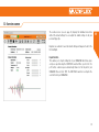
8. Start screen ...................................................................................... 31
9. Servo settings .................................................................................. 32
10. Flight phases .................................................................................... 33
11. Gain (sensitivity) ................................................................................ 34
12. Important remarks before rst ight ................................................... 34
13. Overview screen ............................................................................... 35
14. Telemetry ......................................................................................... 36
15. Optimisation ..................................................................................... 37
16. Binding ............................................................................................ 38
17. Accessories ...................................................................................... 59
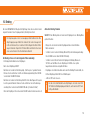
These operating instructions are part of the product. They contain important
information and safety advice. It should therefore be kept at hand and passed
on when selling the product to third parties. Please read carefully before initial
use. For intended use only.
Use a sufcient power supply dimension. Observe installation instructions. Con-
duct range tests regularly. Please also note the extended manual that you get
installed with the WINGSTABI software on your computer.
The device was evaluated according to directives harmonized with European
legislation. You are therefore in possession of a product whose construction
satises the protection objectives of the European Community for the safe
operation of devices.
You can nd the exhaustive CE declaration of conformity as a PDF document
on-
line at www.multiplex-rc.de in the DOWNLOADS section under PRODUKT-INFOS.
1. Safety information
1.1. CE declaration of conformity

22
1.2. Guarantee and limitation of liability
Electrical and electronic equipment which has the crossed out wheelie bin
symbol should not be disposed along with household waste, but rather via a
suitable disposal system. In countries belonging to the EU (European Union),
electrical or electronic equipment may not be disposed of along with general
household waste (WEEE - Waste of Electrical and Electronic Equipment, Directive
2002/96/EC).
You can dispose of your old equipment at public municipal collection points (e.g.
recycling facilities) free of charge. The equipment will be properly disposed of
free of charge here. By returning your old equipment, you are making a valuable
contribution towards environmental protection!
1.3. Disposal
MULTIPLEX Modellsport GmbH & Co.KG does not assume any liability for loss,
damage or costs which arise through the improper use and operation of our
products, or which are connected with such operation in any way. As far as is
legally permissible, the obligation of MULTIPLEX Modellsport GmbH & Co.KG
to provide compensation for damages, on whatever legal basis, is limited to
the invoice amount of the quantity of MULTIPLEX Modellsport GmbH & Co.KG
goods that were directly affected by whatever incident gave rise to the damage.
This does not apply if MULTIPLEX Modellsport GmbH & Co.KG is obliged to
accept unlimited liability in accordance with mandatory law for deliberate or
gross negligence.
Our products are covered by the currently valid statutory guarantee regulations.
If you wish to make a claim under guarantee, please contact the model shop
where you purchased the product. The guarantee does not cover malfunctions
caused by the following:
· Improper operation
· Maintenance that was performed incorrectly, late or not at all,
or performed by a non-authorized body
· Incorrect connections
· Use of non-original MULTIPLEX accessories
· Modications/repairs that were not carried out by MULTIPLEX or
a MULTIPLEX Service Centre
· Accidental or deliberate damage
· Faults due to normal wear and tear
· Operation outside the technical specications or in connection with
components from other manufacturers.
MULTIPLEX Modellsport GmbH & Co.KG
Westliche Gewerbestraße 1 · D-75015 Bretten-Gölshausen
Multiplex/HiTEC Service: +49 (0) 7252 - 5 80 93 33

23
Freely programmable triple-axis gyro system for all RC xed-wing model air-
craft. Having complete control over your model at all times is the dream of any
pilot. The WINGSTABI makes this dream achievable, and ticks every possible
box for beginners and pro-standard yers alike in terms of handling, adjustment
and functionality.
· The WINGSTABI makes any simple radio control set into a fully
programmable RC system
· Gain (sensitivity) on all three axes can be varied separately or
jointly from the transmitter
· Variation factor can be set separately for each axis
· 7, 9 channels, or 12, 16 channels Pro versions with integrated battery backer
· The gyro function is freely assignable for each servo,
i.e. the unit caters for every model application
· Delta mixer, V-tail mixer and ap support
· Flaps can be set to amplify aileron response
· Real-time sensor diagram in the PC software
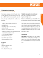
Four ight phases:
1. On/Off
2. Stabilisation for ying in windy conditions
3. Aerobatics and 3D ying
4. Torque-rolling (rock’n’roll at the ying site)
The WINGSTABI is also compatible with all current RC systems:
Graupner, Futaba, M-LINK, Jeti, HiTEC, Weatronic and others.
It supports the following types of signals:
PPM, Futaba S.Bus*, MULTIPLEX SRXL, Graupner SUMD and SUMO, Jeti UDI, JR
XBUX Mode B and S-BUS signal many other systems, such as HiTEC and FrSky.
The latest generation of ultra-precise triple-axis MEMS sensors ensures that the
sensation of ying remains realistic even at extremely high rates of stabilisation,
and the pilot never has the impression of ying a robot. The sleek case, made
of anodised aircraft aluminium, can be installed in any orientation of the model.
The WINGSTABI is straightforward and swift to program using a PC or an APP
with any smartphone or tablet.
Functional description
Heading Hold (HH) is a mode of operation for one or several axes which is
stabilised by means of the gyro, during which signals from the gyro sensors are
evaluated in order to maintain the current ight attitude. The model maintains
the last commanded ight attitude and must be actively commanded into the
next one.
2. Product and function description

24
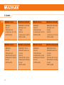
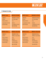
3. Contents
WINGSTABI-7-Channel
· WINGSTABI-7
· Instructions
· 320 mm patch-leads
· 2 x adhesive pad, 32 x 52 mm
· USB-PC-lead (UNI)
WINGSTABI-12-Channel
· WINGSTABI-12
· Instructions
· 320 mm patch-leads
· 4x Grommets with screw and
Mounting Eyelets for attaching
the model
· USB-PC-lead (UNI)
WINGSTABI-9-Channel
· WINGSTABI-9
· Instructions
· 320 mm patch-leads
· 2 x adhesive pad, 32 x 52 mm
· USB-PC-lead (UNI)
WINGSTABI-16-Channel
· WINGSTABI-16
· Instructions
· 320 mm patch-leads
· 4x Grommets with screw and
Mounting Eyelets for attaching
the model
· USB-PC-lead (UNI)
WINGSTABI-RX-7-DR M-LINK
· WINGSTABI-RX-7-DR M-LINK
with integral receiver
· 7-channel
· Instructions
· 2 x adhesive pad, 32 x 52 mm
· USB-PC-lead (UNI)
WINGSTABI-RX-12-DR pro M-LINK
· WINGSTABI-RX-12-DR pro
M-LINK with integral receiver
· 12-channel
· Instructions
· 4x Grommets with screw and
Mounting Eyelets for attaching
the model
· USB-PC-lead (UNI)
WINGSTABI-RX-9-DR M-LINK
· WINGSTABI-RX-9-DR M-LINK
with integral receiver
· 9-channel
· Instructions
· 2 x adhesive pad, 32 x 52 mm
· USB-PC-lead (UNI)
WINGSTABI-RX-16-DR pro M-LINK
· WINGSTABI-RX-16-DR pro
M-LINK with integral receiver
· 16-channel
· Instructions
· 4x Grommets with screw and
Mounting Eyelets for attaching
the model
· USB-PC-lead (UNI)

25
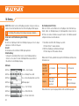
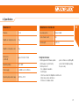
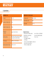
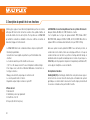
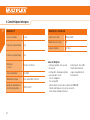
4. Specication
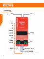
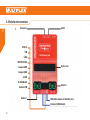
WingStabi LED codes:
· ashing green/red: rmware update
· ashing green: system startup
· ashing red: error:
- No conguration available
- No RC signal
- Stick moves when the WingStabi is switched on
- Model moves when switched on
- Critical error, hardware failure
· green continuous: everything OK,
ailerons twitch slightly signaling
they are ready
WINGSTABI 7/9
Channels 7 or 9
Weight excl. integral receiver 27 g
Weight incl. integral receiver 35 g
Dimensions
(L x W x H)
approx. 54 x 34 x 15 mm
Operating voltage 3.5 to 9.0 V
Power supply 4 - 6 NiXX cells, 2S LiPo/Lilo
Operating temperature range –20°C to +55°C
WINGSTABI RX-7/9-DR M-LINK
Receiving system M-Link 2.4 GHz
Servo channel count 7/9
Aerial length 2 x 16 cm

26
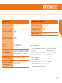
4. Specication
WingStabi LED codes:
· ashing green/red: rmware update
· ashing green: system startup
· ashing red: error:
- No conguration available
- No RC signal
- Stick moves when the WingStabi is switched on
- Model moves when switched on
- Critical error, hardware failure
· green continuous: everything OK,
ailerons twitch slightly signaling
they are ready
WINGSTABI 12/16
Channels 12 or 16
Weight excl. integral receiver 92 g
Weight incl. integral receiver 100 g
Dimensions
(L x W x H)
approx. 74 x 58 x 16 mm
Operating voltage
6.0 to 9.0 V, Power supply only permitted
by using the two battery terminals.
Power supply 5 NiXX cells, 2S LiPo/Lilo/LiFe
Operating temperature range –20°C to +55°C
WINGSTABI RX-12/16-DR M-LINK
Receiving system M-Link 2.4 GHz
Servo channel count 12/16
Aerial length 2 x 37 cm

27
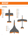
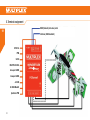
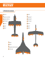
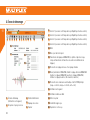
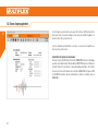
5. Terminal assignment
1
Aileron 1
2
Elevator
3
Rudder
4
Throttle output
5
Aileron 2
6
Flap 1
7
Flap 2
1
Aileron 1
2
V-tail 1
3
V-tail 2
4
Throttle output
5
Aileron 2
6
Flap 1
7
Flap 2
1
Aileron 1
2
Aileron 2
3
Rudder (optional)
4
Throttle output
1 6 7 5
4
3 2
4
4
1
6
1
3
2
5
7
2 3

28
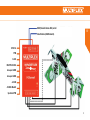
HiTEC SL
PPM
S-BUS
MULTIPLEX SRXL
Graupner SUMD
Graupner SUMO
Jeti UDI
JR XBUS Mode B
Spektrum PPM
MSB (telemetry data bus) serial
Interface (USB/bluetooth)
5. Terminal assignment

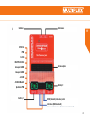
29
HiTEC SL
PPM
S-BUS
MULTIPLEX SRXL
Graupner SUMD
Graupner SUMO
Jeti UDI
JR XBUS Mode B
Spektrum PPM
Switcher
Battery 1
Extensions
Servo outputs
Battery 2
MSB (telemetry data bus) serial
Interface (USB/bluetooth)

30
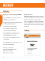
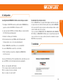
6. Conguration
The following steps are required in order to congure the WINGSTABI:
1. Download the MULTIPLEX Launcher from the download section of the
MULTIPLEX homepage and install it on your PC.
2. The driver for the USB-PC-lead RX+S+Telemetry (UNI) with article number
# 8 5149 will be installed automatically as well.
3. Launch the software after completing the installation.
4. If necessary, manually select the COM-port USB lead.
However, this is usually recognized automatically.
5. Connect the WINGSTABI to the USB lead with the B/D connection.
6. Connect WINGSTABI with power (4.8 or 6 to 9 volts).
7. Use the assistant to congure the WINGSTABI for the rst time and
follow it step by step.
If instead of the USB PC interfaces the optional Bluetooth module is used, please
select the COM port manually by paragraph 4.
Note the blinking codes of the BT-module:
1 Hz: the module is ready and waiting for a connection
10 Hz: The module is in command mode
Duration: The module is connected via BT
7. Installation
Connecting an external receiver:
At WINGSTABI without integrated M-Link receiver connect your own receiver via
enclosed patch cable to the IN slot. Your receiver must be set to the sum signal
output. Please refer to the instructions of the respective manufacturer.
If you are using a WINGSTABI RX-7-DR, WINGSTABI RX-9-DR, WINGSTABI
RX-12-DR pro or WINGSTABI RX-16-DR pro (with integrated receiver) the IN
slot has no function. You could not connect a second receiver for the multiplex
two-receiver mode.

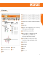
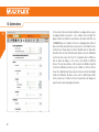
2 63 74 85 91
14
15
16
17 18
19
20
10 11 12
13
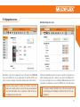
1
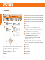
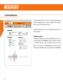
Start screen (device information)
2
Receiver and channel overview
3
Model
4
Servo settings
5
Sensor
6
Flightmode 1
(values can be applied to other ight modes by drag&drop)
7
Flightmode 2
(values can be applied to other ight modes by drag&drop)
8
Flightmode 3
(values can be applied to other ight modes by drag&drop)
9
Flightmode 4
(values can be applied to other ight modes by drag&drop)
10
Tools
11
Firmware update
12
Applying the settings to the WINGSTABI (Symbol ashes red if the settings
must be re-applied because they have changed)
13
Selection between basic and advanced settings
14
Menu (restart WINGSTABI, reset WINGSTABI to default settings,
import WINGSTABI settings, export WINGSTABI settings,
launcher settings, launcher information, end launcher)
15
Selection of the automatic recognition or of a preset COM port
(red = not connected, orange = searching, green = connected)
16
Device information
17
Status information
18
Receiver input
19
Gyro gain
20
Oscilloscope sensor
31
8. Start screen

32
9. Servo settings
Dual rate and expo may be used on the transmitter as normal. Ser-
vo center or neutral rudder position must be set mechanically on the
model.
!
The servo output for the throttle must not be reassigned. This would
pose a danger of undesired engine start-up during programming.
!
It must be ensured that all servo settings are made on the WINGSTABI and not
the transmitter. The trim on the transmitter must remain neutral or zero. Mixers
must be deactivated at all times at the transmitter.
Advanced servo mapping
For models which use more servos than those shown on page 21 of these in-
structions in the standard wiring diagrams, map them in the servo window. Each
servo output is freely assignable in its function. It is however recommended that
servos which have already been assigned be left alone.

33
10. Flight phases
The WINGSTABI has 4 individually usable ight phases.
Flight phase off (Flight phase 1)
The WINGSTABI is switched off and forwards control commands directly from
the transmitter to the servos.
Damping mode (ight phase 2)
For normal ying. External inuences such as crosswinds and landing are mini-
mized. Here we are referring to a type of “wind canceling” functionality.
Full Heading Hold (Flight phase 3)
For elaborate acrobatics. This mode can only be used to a limited extent during
landing and take-off, as it demands a certain level of experience in ying the
WINGSTABI. Stalls are often detected too late by the pilot here. The advantage
is that the model remains absolutely consistent even with heavy winds. What
makes the WINGSTABI special here is that control over the rudder is specially
optimised, thus ensuring a realistic airborne appearance.
Torque-rolls! (ight phase 4)
Extreme heading hold mode. This mode is unsuitable for normal ying. The
model would soar upwards.
How do you activate the fourth ight phase, which cannot be activated in
the standard conguration?
In the software, switch to the receiver settings window “assign fourth ight
phase”. An additional channel with 2-stage switch must be assigned.
This switch is overriding and switches off your WINGSTABI when pressed
in ight phase 1. The previously assigned 3-stage switch for the ight
phases now switches between phases 2, 3 and 4.
i

34
11. Gain (sensitivity)
12. Important remarks before rst ight
Basic settings for WINGSTABI stabilisation
The default settings selected by MULTIPLEX for the stabilising behavior of the
gyro generally tend to err on the safe side, meaning the sensitivity is set rather
low. The sensitivity can be signicantly increased on most models.
Adjusting the sensitivity of the gyro via transmitter
First of all, assign a channel in the receiver window. Then, in the respective
ight phase adjust the “sensitivity via transmitter” function from deactivated to
the desired value range. Select +– 30 when using the device for the rst time.
Agility of the model: Here you can change the rotational speed of the model. For
rst time yers, we recommend using the default settings.
Procedure for the rst ight with the newly installed WINGSTABI in the model:
· Control the WINGSTABI effective directions of the individual axes
· Operate the directional controls
· Select ight phase 1, gyro off, and also do not switch to other ight phases
during the rst ight
· Launch the model and quickly climb to a safe altitude
· Use the trim at the transmitter until the model is in neutral ight
· Land the model
· After the rst landing, the affected trim settings must be transferred to
and thus programmed in the WINGSTABI by quickly toggling the ight
phase switch
· Perform a nal test on the programmed trim settings
· Switch to ight phase 3, heading hold. The rudders must not stray or move
by themselves into end position.
The WINGSTABI is now ready for the rst ight with assisted stabilisation. It is
advisable to always take off in ight phases 1 or 2. Particularly during the early
ights, ight phases 3 and certainly 4 should only be selected at a safe altitude.
Dual rate and expo may be used on the transmitter as normal. Servo
center or neutral rudder position must be set mechanically on the
model.
i
Move the ight phase switch to and for 4 to 5 times quickly. This will
enable the trim settings on the transmitter gained through ying to be
programmed in the WINGSTABI as the neutral position. You can control
the programming of the trim settings by switching to ight phase 3 or
4. It must merely be ensured that the trimmed rudders do not “stray”
out of the neutral position.
i

35
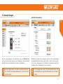
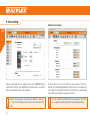
The overview screen (see also page 23) displays the individual menu items
with all the default settings. You can adjust the default settings to suit your
personal ying style.
Beginners are advised to leave the default settings unchanged at least for the
rst few ights.
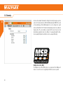
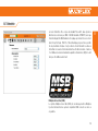
Import function
This enables you to import settings les to your WINGSTABI which have previ-
ously been exported using the MULTIPLEX Launcher. When you click the “Im-
port” button, a window opens automatically. Browse for the le path of your
WINGSTABI les and click “OK”. The MULTIPLEX Launcher now imports the
selected le into your WINGSTABI.
13. Overview screen

36
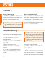
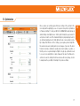
As well as the standard “Deactivated” setting, the Telemetry menu gives you two
options for the data transfer via MSB: M-LINK standard and PROFI-TX as well
as Telemetry-Display. The M-LINK standard is the correct setting for all cockpit
and royal transmitters. Pro-TX and telemetry-display provide more advanced
display options. The sensor addresses required for this can be freely selected.
Avoid double assignments at all costs. Address 1 is assigned by default to trans-
mission quality (LQI) and should therefore not be assigned differently.
14. Telemetry
Multiplex Sensor Bus (MSB)
The Multiplex Sensor Bus (MSB) system is a development from Multiplex. It
allows to connect the sensors supporting the MSB in cascades or parallel.

37
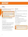
15. Optimisation
Once you have successfully acquired the basic settings of the assistant or the
mode template through ight, you can – if required – then perform optimizations
in “Advanced settings”. To help you with this, the WINGSTABI clearly displays all
default settings in all ight phases. Start by right clicking the page header for
each phase in order to select the standard settings for purely damping mode, for
an optimised damping mode, for fully stabilised mode or even aerobatics mode.
By looking at the differences in the settings, you can gain a greater insight into
the various modes and carefully work in some changes of your own. The modi-
cations should be as minimal in severity and as few in number as possible, so
that they can be recognized during test ights. Step by step optimisation leads
to success more quickly than too many changes at the same time that are too
extreme. Re-save the settings le with a new name after every change, in order
to always have the possibility of returning to the previous settings.

38
16. Binding
If you are using a WINGSTABI with an integral receiver, this must be programmed
to the transmitter. This procedure is referred to as “Binding”.
The binding procedure is necessary in the following situations:
· Initial setup of the receiver
· After resetting the receiver
· After the setting relating to “Fast Response” was changed on the transmitter.
You can nd information concerning this from the operating instructions of
your M-LINK transmitter or M-LINK synthesizer RF module
· After the setting for the transmitted frequency range has been changed.
You can nd more information on this in the operating instructions of your
transmitter or M-LINK synthesizer RF module (“France mode”)
· If the receiver is to be operated with a different M-LINK transmitter
Binding procedure
Step 1: In order to bind, the transmitter and receiver must be brought into
binding mode:
· Bring the transmitter and receiver aerials into close proximity with one another.
· Switch ON the transmitter in binding mode
(refer to the operating instructions of your M-LINK transmitter or M-LINK
synthesizer RF module).
· Switch on the M-Link Telemetry Receiver in binding mode:
Press and hold the SET button on the top of the receiver using a sharp object.
· Plug in the receiver/battery: When the binding procedure is running, the
LED on the receiver ashes rapidly.
· Let go of the SET button now.
The pulse output at the servo output sockets remains switched off
during the binding procedure. This means the servos do not move and
are soft; in modern electric motors, the motor remains switched OFF
due to the absence of an impulse. Even so, please secure the model
and maintain an adequate safety distance!
i
When the receiver is used for the rst time or after being reset, the
binding procedure begins automatically, even if the SET button is not
pressed.
i

39
Step 2: After the transmitter and the receiver are connected, both switch to
normal operation and the LED on the receiver ashes slowly.
Troubleshooting: Binding
Error:
The LED on the receiver ashes rapidly during the binding procedure and for
several seconds after.
Reason:
Unable to nd an M-LINK signal of sufcient strength.
Solution:
· Reduce the distance between your transmitter and the receiver aerials.
· Ensure that your transmitter is connected in binding mode.
· Repeat the binding procedure.
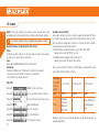
LED codes
LED code 1
LED ON -> no reception
LED code 2
1.6 sec. -> binding process running
LED code 3
1.6 sec. -> normal receiving mode, no errors
LED code 5 acknowledgment signal
LED code 6
1.6 sec. -> between 1 and 19 errors
LED code 7
1.6 sec. -> between 20 and 49 errors
LED code 8
1.6 sec. -> 50 or more errors
Functions of the SET button
If the SET button on top of the receiver is pressed when being turned on, the
binding procedure begins. In receiving mode, two additional functions can be
triggered using the SET button. Which function is selected depends on how long
the button is pressed:
1. Save error counter or FAIL-SAFE position:
Press the SET button for between 0.5 and 1 second.
2. RESET the receiver to default settings:
Press the SET button for longer than 10 seconds.
While the SET button is being pressed, the LED emits timestamps indicating the
length of time the button has been pressed.
Please note: After saving, the LED emits the acknowledgment signal.
The Binding procedure usually only takes a few seconds.
i
Press and
hold the SET
button for
< 2 seconds
Between 2 and 10
seconds
> 10 seconds
LED: OFF ON OFF
Task:
Save error
counter/FAIL-
SAFE
RESET to
default settings
Page is loading ...
Page is loading ...
Page is loading ...
Page is loading ...
Page is loading ...
Page is loading ...
Page is loading ...
Page is loading ...
Page is loading ...
Page is loading ...
Page is loading ...
Page is loading ...
Page is loading ...
Page is loading ...
Page is loading ...
Page is loading ...
Page is loading ...
Page is loading ...
Page is loading ...

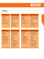
# 8 5194
Klebepad für WINGSTABI 7/9
Adhesive pad for WINGSTABI 7/9 · Tapis adhésifs pour WINGSTABI 7/9
# 8 5195
Mechanischer Ein/Aus-Schalter
Mechanical on/off switch · Interrupteur mécanique on/off
# 4 5188
Bluetooth-Modul
Bluetooth module · Module Bluetooth
# 8 5196
Magnetischer Schalter
Magnetic switch · Interrupteur magnétique
59
17. Zubehör · Accessories · Accessoires
Optionales Zubehör · Optional accessories ·
Accessoires optionnels
Optionales Zubehör · Optional accessories ·
Accessoires optionnels
Accessoires optionnels
Klebepad für WINGSTABI 7/9
# 8 5195
Mechanischer Ein/Aus-Schalter
Accessoires optionnels
Magnetischer Schalter
Magnetic switch · Interrupteur magnétique
Page is loading ...
-
 1
1
-
 2
2
-
 3
3
-
 4
4
-
 5
5
-
 6
6
-
 7
7
-
 8
8
-
 9
9
-
 10
10
-
 11
11
-
 12
12
-
 13
13
-
 14
14
-
 15
15
-
 16
16
-
 17
17
-
 18
18
-
 19
19
-
 20
20
-
 21
21
-
 22
22
-
 23
23
-
 24
24
-
 25
25
-
 26
26
-
 27
27
-
 28
28
-
 29
29
-
 30
30
-
 31
31
-
 32
32
-
 33
33
-
 34
34
-
 35
35
-
 36
36
-
 37
37
-
 38
38
-
 39
39
-
 40
40
-
 41
41
-
 42
42
-
 43
43
-
 44
44
-
 45
45
-
 46
46
-
 47
47
-
 48
48
-
 49
49
-
 50
50
-
 51
51
-
 52
52
-
 53
53
-
 54
54
-
 55
55
-
 56
56
-
 57
57
-
 58
58
-
 59
59
-
 60
60


MULTIPLEX WINGSTABI-RX-9-DR M-LINK Owner's manual
- Type
- Owner's manual
Ask a question and I''ll find the answer in the document
Finding information in a document is now easier with AI
in other languages
Related papers
-
MULTIPLEX Empfaenger Rx 16 Dr Master Web Owner's manual
-
-
-
-
-
-
-
-
-
Other documents
-
HiTEC ePowerbox 17A Owner's manual
-
GRAUPNER MX-12 - PROGRAMMATION Owner's manual
-
-
-
-
-
-
ROBBE HFM12-MX Operating Instructions Manual
-
-
 ACT Europe FUZZY SMM User manual
