N3000S

Essick N3000S User manual

  • Hello! I am an AI chatbot trained to assist you with the Essick N3000S User manual. I’ve already reviewed the document and can help you find the information you need or explain it in simple terms. Just ask your questions, and providing more details will help me assist you more effectively!
Owner’s Manual
Model No.
N3000S
N4000S
N4500S
N5500S
N6500S
N3100D
N4300D
N4800D
N5600D
N6600D
Less Motor Units
N30S
N40/45S
N55/65S
N31D
N43/48D
N56/66D
READ AND SAVE
THIS INSTRUCTION MANUAL
Side and Down Discharge
Evaporative Air Coolers
70932
Rev. 6/02
Evaporative Cooling
Evaporative cooling uses the principle of evaporation to lower the air temperature. Hot, dry air is passed through wetted
filters and is converted to refreshingly cooled air. Essick Coolers make the best use of the evaporative process by
controlling the flow of water, spreading the water evenly over the filters, and keeping a steady stream of cooled air
entering your home. It is exhausted out open windows or doors, carrying heat, smoke and odors along with it. Essick
evaporative coolers are 80% less costly to operate than refrigerated air conditioners.
Cautions: To prevent harm to yourself and others, and to avoid damage to your cooler, PLEASE follow these guidelines.
SAFETY GUIDE LINES & CAUTIONS
When Installing When Operating When Servicing
Make sure that unit is installed on a sound
structure that will support the full operating
weight of the cooler. See page 3.
Make sure that circuit cooler is wired into is
equipped with a (slow blow) breaker large
enough to support the full amperage of the
cooler.
Always shutoff power to the cooler, at the
breaker, before attempting service of any
kind. If not, it can be turned on from inside
the house and start unexpectedly.
Before attempting to transport the cooler to the
mounting location, plan a safe way to move the
cooler and remove the louvers to reduce weight.
To reduce the risk of fire or electrical shock, DO
NOT use this fan with any Solid-state speed
control device.
Never drain cooler water onto your roof.
Water residue may cause you to slip or may
stain your roof.
Do Not connect power to cooler before
installation is complete.
This cooler is equipped with an automatic
thermally protected motor. If it shuts off on its
own for any reason, it can restart without
warning.
If the motor shuts off because of thermal
overload, check into the problem
immediately. If allowed to continue,
permanent damage will occur.
When servicing or installing, always wear gloves,
protective eyewear, and other applicable safety
gear. Never wear slippery-soled shoes when
working on a roof.
Never use a cooler without connecting it to a
duct system or without a sturdy mesh guard over
the outlet.
Never install or service a cooler during a
storm or high wind conditions.
Tools & Materials Required
1. Pliers
2. Screwdrivers 2. Screwdrivers
3. Adjustable wrenches 3. Adjustable wrenches
4. Tubing cutter 4. Tubing cutter
5. 5/32 hex wrench 5. 5/32 hex wrench
6. Electric drill 6. Electric drill
7. Drill bits 7. Drill bits
8. Hammer 8. Hammer
9. Duct caulking 9. Duct caulking
10. #10 sheet metal screws 10. #10 sheet metal screws
11. Safety glasses 11. Safety glasses
12. Wiring supplies (as required by local electric
codes)
12. Wiring supplies (as required by local electric
codes)
13. Duct, as required. A local sheet metal shop can
supply ducting or it may be purchased as a kit.
13. Duct, as required. A local sheet metal shop can
supply ducting or it may be purchased as a kit.
14. Level 14. Level
15. Air diffuser 15. Air diffuser
16. Equipment suitable for cutting hole in roof or wall 16. Equipment suitable for cutting hole in roof or wall
17. ¼” water line 17. ¼” water line
18. saddle valve or faucet adapter 18. saddle valve or faucet adapter
19. ECR-6 wall switch (6 position) 19. ECR-6 wall switch (6 position)
20. Roof stand (if cooler is roof mounted) 20. Roof stand (if cooler is roof mounted)
Location
Location
1. Your cooler installation must comply with local codes. If you are not qualified to install a cooler, get professional help. 1. Your cooler installation must comply with local codes. If you are not qualified to install a cooler, get professional help.
2. Do not install the cooler near vent pipes, chimneys or exhaust pipes. The cooler will draw in fumes into your house. 2. Do not install the cooler near vent pipes, chimneys or exhaust pipes. The cooler will draw in fumes into your house.
3. The drain fitting in the bottom of the cooler must have adequate room for service access. 3. The drain fitting in the bottom of the cooler must have adequate room for service access.
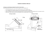
Side discharge
connected to
duct work
Down discharge
into hall
70932
Rev. 6/02
2
Roof Jack
Weight
Model Discharge opening
Shipping Operating
N31D 150 245
N30S
13 ¾” x 13 ¾”
115 195
N43/48D 190 325
N40/45S
17 ¾” x 17 ¾”
185 300
N56/66D 211 340
N55/65S
19 ¾” x 19 ¾”
203 375
Flashing
Boxed
Opening
Roof
Kit
Drain
Duct
Drain
Flashing
Duct
Boxed
Opening
Mounting Requirements
1. Prepare duct to fit model used. See chart below for discharge opening sizes of different models.
2. Assemble all tools and materials needed for installation.
3. Cut opening in roof or wall to fit duct (see # 1). Box in opening and reinforce any cut roof joists or wall studs.
4. Install duct and secure to boxed frame. The duct will fit inside the cooler opening. The duct length from roof to bottom
of cooler should be a minimum of 4” at the closest point, so there is access to the water drain. When installing cooler,
face the drain side toward the downhill side of the duct.
5. Install flashing and seal the duct to prevent water entry.
6. Measure and layout mounting location. A good quality roof stand or cooler pad should be used to mount your cooler.
7. Mount cooler to stand or pad. Cooler must be level front to back and side to side.
8. Be sure to securely fasten all four corners of cooler to stand or pad.
9. Caulk duct to the cooler. Ensure roof or wall opening is sealed well.
Duct Work
The most important principle in duct construction is to keep it simple. Complex duct work is expensive. In attics, long
duct work will reduce the amount of cooling your cooler has produced. The most simple and popular system is to run a
straight duct either down from the roof (roof mount) or through a wall into a central hallway. Air is then pulled to other
rooms by means of open windows.
Remember, an evaporative cooler puts out a lot of air, with most applications
exchanging the air in the house every two minutes.
On this page is a simple duct system. The duct itself is a flexible material that can be
easily adapted to any job. Flexible duct is not necessarily good for use with coolers
because the pipe is restrictive, but it is very easy to use. It is expandable and can be
easily routed. It can be cut with scissors or a knife and wire snips. It is easily connected
to existing duct work or directly to a ceiling diffuser.
Remember: the duct work must be the same size or larger than the cooler
discharge. If not the airflow will be restricted, resulting in poor cooling. It is
recommended to oversize flex duct and install a good transition in round duct.
70932
Rev. 6/02
3
Install Overflow and Drain
Reservoir
Ferrule
Faucet
1. Slide the Rubber Washer over the Drain Bushing and push through the hole in the
bottom of the cooler from the top side.
2. Secure the Drain Bushing from beneath the pan with the Lock Nut. Make sure the
Rubber Washer does not twist while tightening, which could cause it to leak. DO NOT
OVERTIGHTEN.
3. Thread the Overflow Tube into the Drain Bushing and HAND TIGHTEN.
4. If leakage occurs after Reservoir is full, retighten the Overflow Pipe until leaking stops.
A small amount of silicone caulk may be used if necessary.
Float Valve Installation
1. Mount the Float Valve in the hole provided in the Corner Post or in the Float Bracket
attached to the blower.
2. Slip the Fiber Washer over the threaded portion outside the corner post and secure
with the Nut. Be sure the Float does not turn while you are tightening the Nut.
Water Line Connection
Find the closest outside water faucet, and install a Water Connection Kit (not included
with cooler) as shown. If an exterior faucet is not available, locate the closest cold water
pipe and install a saddle valve assembly.
Route tubing to cooler. Place Compression Nut and Ferrule over end of tubing. Insert
the tubing into float valve and tighten Compression Nut to secure. NOTE: Over
tightening a compression fitting will cause that fitting to leak. It is best to secure the
connections, turn on the water, and then snug the fitting until leaking stops.
Adjusting Water Level and Float
To adjust water level, bend the float valve rod.
Check all water connections for leaks.
Make sure the Float Valve cuts off completely when the desired water level has been
reached (½” to ¾” below top of Overflow Tube). If the float does not stop the water
completely, the water level will rise and run out the Overflow Tube.
Double check the Overflow Tube for leaks.
Motor Mounting
1. Wire motor as shown on page 3. Double check wiring diagram on motor
name plate to ensure proper wiring.
2. Place motor into cradles of motor mount as shown. Be sure motor cradles fit
into grooves in grommets.
3. Secure motor using the saddle clamps.
Operation with Essick 6 position switch (ECR-6)
Switch setting Blower operation Pump operation
Off Off Off
Pump Only Off On
Low Vent Low Off
High Vent High Off
Low Cool Low On
High Cool High On
Mount
Motor
70932
Rev. 6/02
4
Caution: Disconnect all electrical power at the breaker or fuse box before you begin to install, service or open your cooler
Warning: to reduce the risk of fire or electrical shock, DO NOT use this fan with any solid-state speed control device.
Electrical Connections
1. All wiring must conform to local codes.
2. If this unit is to be controlled by a remote switch, use an Essick 6-position switch (ECR-6) or an equivalent UL switch
with an electrical rating of 120 Volt, 25 Amp and 1 ¼ HP maximum.
3. The junction box is mounted in the corner of the unit. A knock-out is
provided for connecting electrical conduit.
4. All wiring connections must be made inside the junction box. See wiring
diagram below.
Note: If you have a one speed motor, the low speed settings of your switch
will not be operative.
Motor Installation and Adjustment: (IMPORTANT INFORMATION)
Complete the following before you fill the cooler pan with water.
1. Install the motor pulley with the threaded side out.
2. Tighten the set screw opposite the threaded side onto the flat of the shaft.
3. Loosen the set screw on the threaded side of the pulley until that jaw rotates freely.
4. Turn the jaw clockwise until pulley is fully closed, then turn the jaw counterclockwise until the set screw is over the
closest flat spot. This is the fully closed position. closest flat spot. This is the fully closed position.
5. From the fully closed position open the pulley 3 full turns and tighten the set screw. DO NOT tighten the set screw
onto the threads. This will damage the pulley.
5. From the fully closed position open the pulley 3 full turns and tighten the set screw. DO NOT tighten the set screw
onto the threads. This will damage the pulley.
6. Find the amperage on the motor nameplate. 6. Find the amperage on the motor nameplate.
7. Install the louvers and ensure exhaust openings in the structure (usually windows) are open to the required position. 7. Install the louvers and ensure exhaust openings in the structure (usually windows) are open to the required position.
8. Start the cooler on high vent (no pump). 8. Start the cooler on high vent (no pump).
9. Using a clamp-type ammeter, check the motor amperage by clamping the ammeter around the incoming white lead. 9. Using a clamp-type ammeter, check the motor amperage by clamping the ammeter around the incoming white lead.
10. If amperage is less than motor nameplate amps, remove the belt, loosen the adjustment set screw and close the
pulley one full turn. Tighten the adjustment set screw, replace the belt and check amperage again. Repeat as
necessary until amperage reads just under motor nameplate.
10. If amperage is less than motor nameplate amps, remove the belt, loosen the adjustment set screw and close the
pulley one full turn. Tighten the adjustment set screw, replace the belt and check amperage again. Repeat as
necessary until amperage reads just under motor nameplate.
11. If amperage is too high, remove the belt, loosen the adjustment set screw and open the pulley one full turn. Tighten
the adjustment set screw, replace the belt and check amperage again. Repeat as necessary until amperage reads just
under motor nameplate.
11. If amperage is too high, remove the belt, loosen the adjustment set screw and open the pulley one full turn. Tighten
the adjustment set screw, replace the belt and check amperage again. Repeat as necessary until amperage reads just
under motor nameplate.
12. When amperage reads correctly, adjust belt tension as necessary and recheck belt alignment. 12. When amperage reads correctly, adjust belt tension as necessary and recheck belt alignment.
Start Up
Start Up
Before starting your cooler for the first time, check the following.Before starting your cooler for the first time, check the following.
Cooler is grounded and all electrical connections are
safe and secure.
Cooler is grounded and all electrical connections are
safe and secure.
Cooler is level and duct is sealed. Cooler is level and duct is sealed.
Blower wheel does not rub housing. Blower wheel does not rub housing.
Water supply is turned on. Water supply is turned on.
Drain fitting and water connections are secure and do
not leak.
Drain fitting and water connections are secure and do
not leak.
Float is adjusted properly. Float is adjusted properly.
Motor amperage is set to manufacturer’s
specifications.
Motor amperage is set to manufacturer’s
specifications.
Belt is tensioned properly. Belt is tensioned properly.
Pulleys are aligned. Pulleys are aligned.
Water flows from the water troughs evenly and pads
wet uniformly.
Water flows from the water troughs evenly and pads
wet uniformly.
Check switch operation. See page 3.Check switch operation. See page 3.
COOLER JUNCTION BOX
2
SPEED
BLOWER
MOTOR
PUMP
WHITE
GREEN
BLACK
RED
BLACK
GREEN
WHITE
FACTORY WIRING
FIELD WIRING
WIRE NUT
NOT FURNISHED
WHITE
with
BLACK
STRIPE
BROWN
RED
341
BA
6 POSITION
SWITCH
GREEN
(TO GROUND)
BLACK
WHITE
WALL SWITCH BOX
120
VOLT
A/C
70932
Rev. 6/02
5
Trouble Shooting
Problem Cause Remedy
Motor cycles on and off
Excessive belt tension
Blower shaft not spinning freely
Circuit breaker not large enough
Adjust belt tension
Lubricate or replace bearings
Consult a licensed electrician
Fails to start
No electrical power
Circuit breaker tripped or fuse blown
Check all electrical connections and cords
Reset circuit breaker or replace fuse
Water draining from overflow
Float improperly adjusted Adjust float
Blower vibrates excessively
Belt or pulley loose
Blower wheel out of balance or out of alignment
Debris in blower housing
Adjust belt or tighten pulley
Replace the blower wheel
Clear debris
Not cooling
Blocked water lines
Windows opened too little or too much.
Uneven pad wetting
Pump clogged or failed
Pads plugged with dirt and water deposits
Clear incoming water line, float and water distributor of blockages.
Adjust window openings
Level water trays, check for blocked water slots in water trays
Clean pump or replace
Replace pads
This cooler is equipped with an automatic thermally protected motor. If it shuts off on its own for any reason, it
can restart without warning. If this occurs, check into the problem before permanent damage occurs.
Maintenance
Once a month during cooling season, inspect your cooler for leaks, proper belt tension and
alignment, blocked water lines and excessive residue build-up on the pads.
To adjust belt tension, loosen the 4 Adjustment Bolts (2 each side) on the Motor Mount. Adjust
belt tension so that 3 pounds of pressure (lightly push with one finger) will cause the belt to
deflect ¾”, as shown. Retighten the Adjustment Bolts.
Use SAE 20W or SAE 30W non-detergent oil to lube the bearings. Place 2 to 3 drops in the
bearing oil cups at the beginning of the season and no more than once a season during cooling
season. If the motor has oil holes (usually plugged with yellow caps that read “OIL” at either
end of the motor) oil the motor also, following the same procedure as for bearings.
3/4"
Note: Excessive oil in the bearings may leak out and be drawn into the air stream.
Excessive oil in the motor may leak onto the motor windings and damage the motor.
To replace pads
1. Remove louver from cooler.
2. Unhook pad holders and remove.
3. Remove and discard old pad.
4. Clean water deposits from the louver. If the paint is chipped or rust spots occur sand the
spots and paint with a rust resistant exterior paint.
5. Place new filter in louver and tuck in to prevent hot air from bypassing.
6. Replace pad holders and hook into place.
7. Replace louver in cooler.
Note: It is best to replace filter pads at the end of the season
. Old filter pads soak up lime
and salts that can rust louvers and the cabinet during the wet, rainy winter months.
At the end of the season
1. Remove the Overflow Tube and let the water drain from the reservoir. (The bushing is
threaded to accept a standard garden hose. If desired, a garden hose may be used to
route water away from your house.) Replace the Overflow Tube when you start the cooler
for the next season.
2. Rinse dirt and debris from the pan and clean any water deposits that may have collected
in the reservoir or on any interior surface of the cooler.
3. If the paint is chipped or rust spots occur sand the spots and paint with a rust resistant
exterior paint.
4. Remove the belt and hang it from the motor pulley.
Note: Do not get water on the Fan Motor or Pump Motor. This will cause damage.
If freezing weather occurs in your area, it is best to shut off the water supply at the source and drain the supply line to
the cooler.
A cooler cover is recommended to prevent rain and weather from damaging your cooler.
To prevent the Shaft from rusting, coat with a wax based lubricant. Allow Lubricant to dry completely and all fumes to
disperse before turning on the cooler.
70932
Rev. 6/02
6
LIMITED WARRANTY
This warranty is extended to the original purchaser only. It does not cover damages incurred during shipping or
through accident, neglect, or abuse by the owner. Essick Air Products does not authorize any person or representative to
assume any other or different liability in connection with this cooler.
Terms and conditions of warranty
The bottom pan is guaranteed against leakage due to rusting out for five years. All other original parts provided by
Essick Air Products are warranted against defects in material or factory workmanship for One Year.
Exclusions from the warranty
Essick Air Products is not responsible for incidental or consequential damage resulting from any malfunction.
Essick Air Products is not responsible for any damage occurring from the use of water softeners, chemicals, descale
material, or if a higher horsepower motor than what Essick Air Products recommends is used in the unit.
Essick Air Products is not responsible for the cost of service calls to diagnose cause of trouble, or labor charge to repair
and/or replace parts.
How to obtain service under this warranty
Contact the Dealer where you purchased the evaporative cooler. If for any reason you are not satisfied with the response
for the Dealer, contact Customer Service Department: Essick Air Products Inc. 5800 Murray Street, Little Rock, Arkansas
72209. 1-800-643-8341.
No. Description N30S (qty) N40/45S (qty) N55/65S (qty) N31D (qty) N43/48D (qty) N56/66D (qty)
1 Blower cutoff 501583 504294 70568 501583 504280 70568
2 Front panel 70757 70756 504237
3 Pump 506669 506669 506674 506669 506669 506674
4 Pump bracket 504281 504281 504281 504281 504281 504281
5 Float valve 502389 502389 502389 502389 502389 502389
6 Water hose 598401 598474 598472 598474 598474 598472
7 Splash baffle 70256 (2) 70256 (2) 70256 (2)
8 Blower housing 513028 513039 513027 513029 513026 513027
9 Bottom pan 70761 70759 504219 504215 504217 504219
10 Blower wheel 30318 30322 30323 30318 30322 30323
11 Shaft 30241 30238-02 30238-01 30241 30238-02 30238-01
12 Bearing 70926 (2) 60PB (2) 60PB (2) 583000 (2) 60PB (2) 60PB (2)
13 Thrust washer 501244 (2) 501241 (2) 501241 (2) 501244 (2) 501241 (2) 501241 (2)
14 Blower pulley 583009 30314 30314 583009 30314 30314
15 Belt 582093 582085 582088 582086 582085 582088
16 Motor pulley 30315 30315 30316 30315 30315 30316
17 Saddle clamps 524162 524162 524162 524162 524162 524162
18 Motor** 581188 581188/50310 50310/30491 581188 581188/50310 50310/30491
19 Motor cord 595129 595129 595129 595129 595129 595129
20 Float bracket 70413 70413 70413 70413 70413 70413
21 Overflow assembly 70613 70613 70613 70613 70613 70613
22 Tube holder 524304 (3) 524304 (6) 524304 (6) 524304 (4) 524304 (8) 524304 (8)
23 Motor mount 515160 512574 590509 515160 512574 590509
24 Water distributor 512251 512548 512546 512549 512547 512545
25 Top pan 70760 70758 504205 504201 504204 504205
26 Junction box 504265 504265 504265 504265 504265 504265
27 Pump receptacle 595121 595121 595121 595121 595121 595121
28 Motor receptacle 595098 595098 595098 595098 595098 595098
29 Pad retainer (back) 504255 (3) 504256 (9) 504257 (12) 504255 (6) 504256 (12) 504257 (16)
* Pad retainer (side) 504253 (6) 504253 (6)
30 Pad set 512558 512561 512563 512560 512562 512564
31 Louver (back) 504260 504285 (3) 504264 (3) 504260 (2) 504285 (4) 504264 (4)
* Louver assembly (back) 70941 70945 (3) 70946 (3) 70943 (2) 70945 (4) 70946 (4)
32 Water tray (back) 504268 504269 (3) 504270 (3) 504268 (2) 504269 (4) 504270 (4)
33 Corner post (w/float hole) 504304 504246 504249 504304 504246 504249
* Corner post (plain) 504303 504245 504248 504303 (3) 504245 (3) 504248 (3)
34 Blower brace 504302 (2) 504296 (2) 504301 (2) 504308 (4) 504289 (4) 504302 (4)
35 Bearing support 70925 70924 70923 70925 70924 70923
36 Pump basket 70801 70801 70801 70801 70801 70801
* Louver (side) 504258 (2) 504258 (2)
* Louver assembly (side) 70940 (2) 70942 (2)
* Water tray (side) 504266 (2) 504266 (2)
* Set collar 524330 524331 524331 524330 524331 524331
*-not shown
**Motor sold separately
Quantity 1 unless otherwise shown.
70932
Rev. 6/02
7
Louver assemblies include louver, water tray, pad and pad retainers
Replacement Parts
Cooling Your Home
Your cooler and doors, windows, or vents make up the
two parts of your air cooling system. You control the
airflow to your rooms by opening doors, windows, or
vents. You must have door, window, or vent openings to
let air out when your cooler is running. The total opening
amount of open area you need is shown below.
Model Total Open Area
N30S & N31D 6 Square feet minimum
N40/45S & N43/48D 9 Square feet minimum
N55/65S & N56/66D 12 Square feet minimum
Getting The Best Performance From Your Cooler
Your Evaporative Cooler is engineered to give years of
trouble free operation: however, there are ways to
increase the life span and performance of your cooler.
Maintenance
Maintenance is the most important thing you can do to
insure maximum cooling and trouble free operation.
Service your cooler at the beginning of the season and
inspect it several times during the season.
Filter Pads
Change the filter pads at least twice a year. Hard water
areas may require more frequent filter changes.
Bleed Off
A bleed off system is simple, inexpensive and easy to
install. It will greatly reduce the amount of mineral
deposits in your cooler and extend the life of your pads
and your cooler.
Insulation and Attic Vents
An insulated home is much easier to cool. Insulating
ductwork increases cooling efficiency by reducing heat
gain in your duct work. Also, attic vents keep your attic
cooler and makes your coolers job easier and your
house more comfortable.
Shading
Mounting a cooler in the shade or the sun makes little
difference as to temperature of the air produced by the
cooler. However, placing the cooler in the shade will
deny algae the sunlight it requires to grow and may
extend the life of your pads.
70932
Rev. 6/02
8
/