La Crosse Technology WS-3510 Quick Operation Manual
- Category
- Weather stations
- Type
- Quick Operation Manual
This manual is also suitable for

5
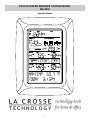
TOUCH-SCREEN WEATHER STATION MODEL
WS-3510
QUICK OPERATION GUIDE
1 Shipping Contents
The shipping contents of the touch-screen weather station WS-
3510 include the touch-screen weather station, a remote
temperature/humidity sensor, the respective connecting cables,
an AC adapter and the PC software package on CD-ROM.
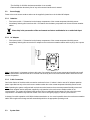
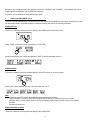
2 Connections
The use of the direct cable connection between the touch-screen
weather station and remote temperature/humidity sensor depends on
the chosen operating mode (see Item 3 Power Supply).
3 Power Supply
Depending on the type of data transmission from remote tempera-
ture/humidity sensor to touch-screen weather station, the units can be
supplied with power in the following possible combinations:
•
With cable connection or 433 MHz wireless transmission: touch-
screen weather station batteries, remote temperature/humidity
sensor batteries.
•
With 433 MHz wireless transmission: touch-screen weather station
AC adapter, remote temperature/humidity sensor batteries.
•
With cable connection: Both units supplied by AC adapter.
The last mentioned cable connection avoids battery wear-out and
allows data transmission less prone to interferences.
4 Putting into Operation
For transmission security, first the remote temperature/humidity sensor
and in immediate after the touch-screen weather station must be put
into operation by power being applied to it.
By doing this full scale operation of the total system of the touch-screen
weather station is ensured.

6
It is beneficial to tentatively put the system into operation in close
proximity (e. g. on a table) in order to ensure correct function in the
configuration it is intended to be used.
5 System Start
After inserting the batteries or respectively connecting the AC adapter
the LCD of the touch-screen weather station will for a few seconds
display all possible segments.
Immediately after this the unit will enter the check mode during which
for about 15 minutes all measured and received weather data are being
switched through, updated and displayed.
This phase allows the user of the touch-screen weather station to check
all cables for correct connection and all components for correct
function.
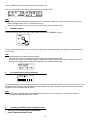
After completing the check mode – which can also be terminated
prematurely by once touching the TIME display in the upper left section
of the LCD – the touch-screen weather station will automatically switch
to the normal display mode from which all further setting can be
performed by the user.
Note:
•
Reception of the radio-controlled time information will only take
place after completion of the check mode (approx. 15 minutes).
This mode can however be discontinued and the time and date can
be set manually.
•
Prior to manual setting or reception of WWVB radio-controlled time
information there will be no recording of weather history data.
6 Placement
After the touch-screen weather station has been checked for correct
function with regard to the above points and found fit, the mounting of
the system components can take place. It must be ensured however
that all components work properly from their chosen mounting or
standing locations. If there appear to be problems with the 433 MHz
wireless transmission they can mostly be overcome by slightly moving
the mounting locations.

7
7 Setting Up
•
All settings of the touch-screen weather station are performed by
means of menu steps in the text section of the touch-screen
weather station (last two lines on the lower part of the LCD). This
menu for basic settings and basic displays is started by slightly
touching (not pressing!) the center of the text display during
normal display mode.
•
All further actions and functions of the touch-screen weather
station are started by touching the switching areas appearing in
star (٭) symbols (in the text section only) or the displayed values
on the touch screen respectively.
•
For a number of value displays touching the display twice will lead
to further displays or functions. All setting and display facilities only
pertain to the presently displayed value or function.
•
The setting of functions, values and units is in all modes performed
by use of the switching areas ٭ON٭ or ٭OFF٭, ٭UP٭ or ٭DOWN٭
or by direct unit selection.
•
Advance to any next menu step with ٭NEXT٭, leave or terminate
all respective modes with ٭EXIT٭.
•
Every programming step activated by touching a switching area on
the touch screen is acknowledged by an audible signal (with
buzzer switched ON).
•
If during any process previously activated by use of the touch
screen no further action is activated for about 20 seconds, the
active process is automatically terminated and switched back to the
normal display mode (automatic time-out).
8 PC Connection
Note:
Please read the Help file on your CD-ROM before connecting the
WS 3510 to your PC.
An important feature exceeding the mere display on the LCD, the
touch-screen weather station allows the read-out of all measured and
displayed time and weather data in the form of complete history data
sets on a PC.
The wiring between touch-screen weather station and PC takes place
by means of the included COM port cable. Furthermore the “Heavy

8
Weather Pro“ software package also included in the shipping contents
must be installed on the PC.
For further details to the subject “PC Connection“ please see the Help
File on the installation disk.
Note:
•
When first putting the touch-screen weather station into operation
the history memory will be empty (no data).
•
Data read-out by means of the PC is only possible after at least 3
data sets have been stored (15 minutes after setting of a valid
time). It is therefore recommended to connect the PC and start the
Heavy Weather Pro software only after this time period has
passed.
Important Note:
•
User is recommended to carefully read the main operation
manual for set up details. And further utilization of the PC
program refers to the "Help" file (opened by clicking the Ques-
tion mark button in menu bar) of the Heavy Weather program.
(The Wind and Rain measurements are not applicable to the
model WS-3510.)

1
TOUCH-SCREEN WEATHER STATION MODEL
WS-3512
Operation Manual

2
Table of Contents
1 ................. General
2 ..................Important Touch-screen Operating Notes
3 ................. Putting into Operation
3.1............ Wiring the System
3.2............ Power Supply
3.2.1 ...... Batteries
3.2.2 ...... AC Adapter
3.2.3 ...... Cable Connection
3.3............ System Start
3.4............ Placement
4 ................. Setting Up
5 ................. Display of stored Min/Max Values and Alarm Value Settings
6 ................. Radio Controlled WWVB Clock
7 ................. Weather Tendency
8 ................. Air Pressure History
9 ................. Operating and Setting of Various Functions
9.1............ Air Pressure
10 ............... Additional Information to Function Outdoor Temperature
11 ............... Operating and Setting the Backlight, Buzzer and Alarm
11.1.......... EL Backlight
11.2.......... Buzzer
11.3.......... Alarm
12 ............... PC Connection
12.1.......... Data Storage
12.2.......... Data Recall
12.3.......... Connections and Software
13 ............... Technical Data
13.1.......... Outdoor Data
13.2.......... Data Transmission by 433 MHz Signal
13.3.......... Data Transmission by Cable
13.4.......... Indoor Data
13.5.......... Power Supply
13.6.......... PC Connection
13.7.......... Dimensions
14 ............... Warranty Information

3
1 General
Important Note:
Before inserting batteries please carefully read the entire operation manual.
The shipping contents of the touch-screen weather station WS-3512 include the touch-screen weather station, a remote
temperature/humidity sensor, the respective connecting cables, an AC adapter and the PC software package on CD-
ROM.
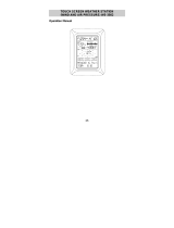
The weather station is equipped with a touch-screen LCD monitor and allows, by use of comprehensive menu controls,
the display of a vast variety of time and weather data (from top to bottom):
•
Radio-controlled time (Time) (also referred to as Atomic Time)
•
Calendar (Date)
•
Wind speed, gust, and direction
•
Air pressure and air pressure history (Pressure, Pressure History)
An important feature of the touch-screen weather station is the ability, through the use of the supplied cable and
software, to supply all measured and displayed time and weather data to a PC and the ability to upload the data
to internet web sites.
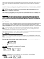
2 Important Touch-Screen Operating Notes
All actions and functions of the touch-screen weather station are started on the touch-screen by slightly touching (not
pressing!) the switching areas appearing in star (٭) symbols (only in the text section at the bottom of the LCD) or the
displayed values respectively.
The setting of functions, values and units is in all modes performed by use of the switching areas ٭ON٭ or ٭OFF٭, ٭UP٭
or ٭DOWN٭ or by direct unit selection.
You can advance to the next respective menu step with the ٭NEXT٭ area or leave all respective modes with ٭EXIT٭.
Every programming step activated by touching a switching area on the touch-screen is acknowledged by an audible signal
(with buzzer switched ON).
If during any process no further action is activated for about 30 seconds the active process is automatically terminated
and switched back to the normal display mode (automatic time out).
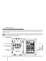
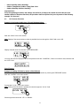
Touch-screen "switching area" on LCD:
Date section
Time section

4
3 Putting into Operation
It first must be decided whether battery or AC (using the included adaptor) power will be used to operate the system. Both
methods allow the connection of remote temperature/humidity sensor and touch-screen weather station by cable or 433
MHz wireless signal.
Note:
When putting the wireless weather station into operation it is important to first perform a complete wiring and setup
of the system in the configuration you intend to use. This serves as a test of all components for correct function before
placing and mounting them in their final destinations.
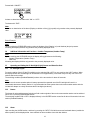
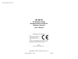
3.1 Wiring the System
The direct cable connection of remote temperature/humidity sensor and touch-screen weather station can be used when:
PC/COM port
receptacle
AC adapter receptacle
Remote Thermo/hygro
sensor receptacle

5
-The flexibility of 433 MHz wireless transmission is not needed.
-Data transmission absolutely free of any environmental interference is wanted.
3.2 Power Supply
Power to the touch-screen weather station can be supplied by batteries or the included AC adapter.
3.2.1 Batteries:
•
First insert two AA 1.5 V batteries into the battery compartment of the remote temperature/humidity sensor.
•
Immediately following this insert three AA 1.5V batteries into the battery compartment of the touch-screen weather
station.
Please help in the preservation of the environment and return used batteries to an authorized depot.
3.2.2 AC Adapter:
•
First insert two AA 1.5 V batteries into the battery compartment of the remote temperature/humidity sensor.
•
Immediately following this connect the AC adapter to the touch-screen weather station and then plug it into a power
outlet.
Note:
In both cases it is important to observe this order of succession since the remote temperature/humidity sensor will
send an identification code which has to be received and stored by the touch-screen weather station within the first few
minutes of operation.
3.2.3 Cable Connection:
One further feature of the direct cable connection mentioned in Item 3.1 above is that in case of AC adapter operation
power is provided not only to the touch-screen weather station but to the remote temperature/humidity sensor as well.
Note:
Operating the system configured with a wired connection between the remote temperature/humidity sensor and
touch-screen weather station and power supplied by only batteries in the touch-screen weather station is not
recommended. The system will operate however there will be considerably shorter battery life due to the high power
requirements. The batteries may however remain in the unit for emergency supply in case of a power failure.
A change from cable operation to 433 MHz wireless transmission or vice versa is possible since the touch-screen weather
station will recognize this change and will automatically switch to the appropriate operating mode.
3.3 System Start

6
After powering up both the remote temperature/humidity sensor and touch-screen weather station the LCD of the touch-
screen weather station will for a few seconds display all possible segments (to ensure all parts of the display can be
seen).
Immediately after this the unit will enter the check mode phase in which for about 15 minutes all measured and received
weather data be cycled through, updated and displayed. During this time period there will be no reception of the WWVB
time information.
Note:
The check mode phase allows the user of the touch-screen weather station to check all cables for correct
connection and all components for correct function.
After completing the check mode the touch-screen weather station will automatically switch to the normal display mode
from which all further settings can be performed by the user. At this point of time the unit will also automatically start
reception of the WWVB time information.
Important Note:
Reception of the radio-controlled time information will only take place after completion of the check mode
(approx. 15 minutes). In case the user wants to start the system without waiting for completion of the check
mode it can be terminated prematurely by once touching the TIME display in the upper left corner of the LCD.
Prior to manual setting or reception of radio-controlled time information there will be no recording of weather
history data.
3.4 Placement
After the touch-screen weather station has been checked for correct function mounting the system components can take
place. It must be ensured however that all components work properly together at their chosen mounting or standing
locations. If there appear to be problems with the 433 MHz wireless transmission they can mostly be overcome by slightly
moving the mounting locations.
Note:
Commonly the wireless communication between the remote temperature/humidity sensor and touch-screen
weather station in the open field reaches distances of a maximum 330 feet (100 meters) providing that there are no
interfering obstacles such as buildings, trees, vehicles, high voltage lines, etc.
Radio interferences created by PC screens, radios or TV sets can in some cases entirely cut off wireless communication.
Please take this into consideration when choosing standing or mounting locations.
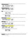
4 Setting Up:
Note:
Because the default settings already determined by the manufacturer it may not be necessary for many users to
perform - outside possibly the Relative Air Pressure (see further down) - any further basic settings. Changes however can
easily be made if desired.
For basic settings the following menu is started by touching the touch-screen in the center of the text display (last two
lines on the LCD). Touching the display ٭SETUP٭ will enter the setup mode.
The basic settings can now be performed in the following successive order:
LCD Contrast
→ Contrast can be set in 8 steps from 0 to 7 (Default 4).
Time Zone
→ Time Zones can be set in the range from -12 to +12 hours (Default -5 hours for Eastern).

7
WWVB Radio-Controlled Clock
(RCC) → ON/OFF. In setting “OFF“ the clock is operating as a normal Quartz clock
(Default RCC ON).
12/24-hour Time Display Format
(Default 12-h Format).
Units
• Temperature Display (Temp) in °F or °C (Default °F).
• Air Pressure (Press) in inHg (inches of mercury – standard U.S. measurement) or hPa (hecto pascal) (Default inHg).
Relative Air Pressure
(Rel. Pressure) → To be set to the locally valid reference air pressure with regard to the local
height above sea level (Default 29.98 inHg).
Weather Tendency
(Tendency) → Setting to a definite switching threshold (2 hPa to 4 hPa) for a change in display of
weather icons (Default 3 hPa).
Storm Warning
(Storm) → Setting to a definite switching threshold for storm warning display at a decrease of air
pressure from 3 hPa to 9 hPa over 6 hours (Default 5 hPa).
Activate/Deactivate storm warning alarm with ٭ON٭ / ٭OFF٭ (Default OFF).
Relearn Mode
(Relearn Tx) → Allows recognition of the remote temperature/humidity sensor (e. g. after a battery change
in the remote temperature/humidity sensor) without the necessity of a comprehensive re-setup of all system components
→ Acknowledge with ٭CONFIRM٭.

8
Default Settings
(Factory Reset) → Allows a reset of all weather data from the non-volatile buffer memory (EEPROM)
and reset of all set and/or stored values to the factory settings set prior to shipment → Acknowledge with ٭CONFIRM٭.
Note:
It will take about 5 minutes for the factory reset process. During this period, the text “Factory Reset In Progress” will be
shown. After the reset process is finished, the LCD will switch off and the text “Remove Battery” will be displayed.
Remove the battery and perform system start again. See “3 - Putting in Operation” paragraph.
Leave the basic settings procedure (Setup Mode) with ٭EXIT٭.
5 Display of stored Min/Max Values and Alarm Value Settings
The selected values are simultaneously displayed and flashing in their respective display sections when showing the
coinciding min/max value.
To recall the measuring and alarm values the menu shown below will have to be activated by touching the touch-screen in
the center of the text display section (last two lines at the bottom of the LCD). The display of the values is started by
touching the displays ٭MINMAX٭ or ٭ALARMS٭.
When ٭MINMAX٭ is selected the below shown menu step is activated, which in turn leads to the displays of the stored
Min/Max values by use of ٭MIN٭ / ٭MAX٭ field.
Note:
During individual display of the stored Min/Max values the top line of the LCD screen will automatically display the
time and date of the record.
The following menu item will appear upon touching the display ٭ALARMS٭. By selecting *LO AL* or *HI AL* the unit will
display the set low and high alarm values. These values can be directly selected individually.

9
Because of the constant access to the opposite menu items, ٭MINMAX٭ and ٭ALARMS٭, it is possible at any time to
toggle between the MIN/MAX and ALARMS value displays.
Any action can immediately be terminated through ٭EXIT٭.
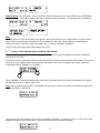
6 Radio-controlled WWVB Clock
The radio-controlled WWVB clock is controlled by the radio signal of the WWVB time code sensor and will thus set time
and date automatically. Under bad reception conditions however both can be set manually as follows:
Setting the Time
The action is started by touching the time display in the TIME section of the touch-screen.
Select ٭TIME٭ in the menu section (last two lines on the LCD).
Set the hours and minutes. Leave the mode with ٭EXIT٭ or wait for automatic time-out.
Setting the Date
The action is started by touching the date display in the DATE section of the touch-screen.
Set the year, month and date and day. Leave the mode with ٭EXIT٭.
Note:
By twice touching the DATE section the display will toggle between the following:
•
Date in DD.MM.YY format (24-hour time format) or Date in MM.DD.YY format (12-hour time format)
•
Weekday, Date of month, Month (24-hour format) or Weekday, Month, Date of month (12-hour time format)
•
Seconds
•
Set wake-up alarm time
Setting the Wake-up Alarm
The action is started by touching the time display in the TIME section.

10
Press ٭ALARM٭ in the menu section (last two lines on the LCD).
Set hours and minutes of the wake-up time. Leave the mode with ٭EXIT٭.
Note:
•
The wake-up alarm is activated/deactivated by twice touching the TIME section. Here the alarm symbol (((•))) will
show or disappear after ٭EXIT٭ (or automatic time-out).
•
When the alarm sounds, user may "touch" any section on the LCD to stop the alarm.
7 Weather Tendency
Call up the tendency display by touching the weather symbol in the TENDENCY section.
The text section (last two lines on the LCD) will show since when (with time and date) the weather corresponding to the
icon occurred.
Note:
•
Up and down arrow indicate weather tendency
•
Advanced storm warning is displayed by Rainy symbol with a flashing down arrow
•
Every minute, when a new pressure reading is obtained, this value is compared to pressure readings from last 2
hours and the biggest resulting difference is displayed in the difference barometer.
8 Air Pressure History (Pressure History)
The air pressure history shows the progress of the air pressure over a time period of 24 or 72 hours in the form of a 7-step
bar graph, where the length of the utmost right bar represents the present air pressure and the remaining bars show the
air pressure over the selected period of time.
Note:
The time resolution of the bar graph can be changed from fine (0 to -24 h) to coarse (0 to -72 h) and back by once
touching the PRESSURE HISTORY section.
9 Operating and Setting of the following Functions:
•
Air Pressure (Pressure), Relative and Absolute
•
Indoor Temperature (Indoor Temp)

11
•
Indoor Humidity (Indoor Humidity)
•
Outdoor Temperature (Outdoor Temp), Dew Point
•
Outdoor Humidity (Outdoor Humidity)
Important Note!
Since the operating procedures and settings are similar for all steps to be carried out on the touch-screen
weather station for the above functions, the procedure shall be explained only once by means of the following
example “Air Pressure”.
9.1 Air Pressure (Pressure)
Example for Activating the Displays of Stored Maximum Values
Call up the menu on the text section by touching the PRESSURE section.
Start with ٭MAX٭ in the menu section.
Note:
Display of the stored minimum values is possible from here through the ٭MIN٭ field on the LCD.
Display of stored value. Proceed with ٭MAX PRESSURE٭.
You may now reset the displayed value to the present value with ٭CONFIRM٭, if there is no need to reset, advance with
the ٭EXIT٭ field.
End of Example
Example for Setting of Alarms by means of the HI Alarms
As in the example above here too call up the menu on the text section by touching the PRESSURE section.
Start with ٭ALARM٭ in the menu section.
Proceed with ٭HI AL٭ in the menu section.
Note:
Setting of the LO alarms is possible from here through the ٭LO AL٭ field.
Set the high alarm value with ٭UP٭ or ٭DOWN٭.

12
Proceed with ٭ON/OFF٭.
Activate or deactivate the alarm with ٭ON٭ or ٭OFF٭.
Terminate with ٭EXIT٭.
Note:
Activation or deactivation of the alarm (Display or deletion of the (((•))) symbol) only pertains to the presently displayed
value.
End of Example
Note:
Twice touching the PRESSURE section toggles the displays of the Relative (rel) and Absolute (abs) air pressure.
All setting and display facilities only pertain to the presently displayed value.
10 Additional Information and Functions - Outdoor Temperature (Outdoor Temp)
Note:
By twice touching the OUTDOOR section the display will toggle between the following:
•
Outdoor Temperature (Outdoor Temp)
•
Dew Point
All setting and display facilities only pertain to the presently displayed value.
11 Operating and Setting the EL Backlight (Light), Buzzer and Alarm Sections
11.1 EL Backlight (Light)
For easier reading of the LCD the EL backlight can be switched ON or OFF by once touching the LIGHT section. When
the display shows “ON” the backlight will be switched on for approximately 15 seconds every time any one of the LCD
sections has been touched.
The switching condition (Enabled/Disabled) is shown in the text section for about 30 seconds.
Note:
When the touch-screen weather station is battery operated the repeated use of the EL backlight will result in a
considerable decrease of battery lifetime. It is recommended to either operate the touch-screen weather station with the
included AC adapter or entirely deactivate the EL backlight (see above).
11.2 Buzzer
The buzzer for acknowledgement of selecting a field or alarm signals of the touch-screen weather station can be switched
ON or OFF by touching the BUZZER section.
The switching condition ON or OFF is displayed directly in the BUZZER section as well as for about 30 seconds in the text
section (Enabled/Disabled).
11.3 Alarm
Upon touching the ALARM section, and then by pressing the ٭NEXT٭ field all those set and activated alarms (outside the
wake-up alarm) will be displayed that have reached an alarm condition since their last deletion.

13
Here for every respective alarm the time and date of appearance can be displayed by touching ٭ALARM٭.
12 PC Connection
12.1 Data Storage
For a comprehensive weather history the touch-screen weather station allows the internal storage of up to 1750 complete
sets of weather data with time and date. These data sets are stored in non-volatile ring buffer memory (EEPROM) and will
not be lost even in case of an interruption of power supply (e. g. change of batteries).
If the memory capacity of the touch-screen weather station is exceeded the oldest data sets stored will be overwritten by
the new ones recorded.
12.2 Data Recall
The weather data stored can only be read out, processed and displayed by means of a PC. Also the settings of the storing
intervals from 1 minute to 24 hours for the storage of data sets can only be performed by means of a PC.
12.3 Connections and Software
The wiring between touch-screen weather station and PC takes place by means of an included COM port cable. The
“Heavy Weather Pro 3510“ software package also included in the shipping contents must be installed on your PC.
This software allows the display of all present weather data with graphic symbols. It further allows the display, storage and
printing of history data sets, whose volume exceeding the maximum 1750 data sets of the touch-screen weather station is
only limited by the capacity of the PC’s main memory.
The present weather data can be loaded to web sites by means of the “Web Publisher“ software. History data can be
displayed as diagrams and graphs by means of the “Heavy Weather Pro“ software.
Important note:
For further details to the subject “PC Connection“ and Program utilisation, please see the "Help" File (under the
Question mark button in menu bar) of the Heavy Weather Program. (The Wind and Rain measurements are not
applicable to the model WS-3510.)
13 Technical Data
13.1 Outdoor Data:

14
Transmission Range in Open Field:.....330 feet max (100 meters)
Measuring Intervals Outdoor Data: ......every 128 seconds
Temperature Range:……………………-40°F to +139.8° F (-40 °C to +59.9 °C) (Display “OFL” if outside this range)
Resolution: ...........................................0.2°F (0.1 °C)
Measuring Range Rel. Humidity: .........1% to 99%
Resolution: ...........................................1%
13.2 Data Transmission by 433 MHz Wireless Signal:
Measuring Intervals remote temperature/humidity sensor: 128 seconds
13.3 Data Transmission by Cable:
Measuring Intervals remote temperature/humidity sensor: 128 seconds
13.4 Indoor Data:
Measuring Intervals Indoor Data:.........every 20 s
Temperature Range: ............................-40°F to +139.8° F (-40 °C to +59.9 °C) (Display “OFL” if outside this range)
Resolution: ...........................................0.2°F (0.1 °C)
Measuring Range Rel. Humidity: .........1% to 99%
Resolution: ...........................................1%
Measuring Range Air Pressure:...........27.17 to 31.90 inHg (300 hPa to 1099 hPa)
Resolution: ...........................................0.01 inHg (0.1 hPa)
Alarm Duration: ....................................about 2 minutes
13.5 Power Supply:
Base Station:
Batteries: ..............................................3 x AA batteries (Alkaline Batteries recommended, Life Cycle without EL backlight
approx. 1 year). When batteries require replacement for the touch-screen weather
station, the low battery indicator will light up on the LCD.
or AC Adaptor: .....................................AC Adapter INPUT 110VAC / 60Hz (use only the included Adapter).
Recommended for PC Connection and frequent use of EL Backlight)
Remote temperature/humidity sensor:
Batteries: ..............................................2 x AA batteries (Alkaline Batteries recommended, Life Cycle approx. 1 year)
or ..........................................................Power provided via cable from the touch-screen weather station by using the AC
adapter
13.6 PC Connection:
Wiring: ..................................................COM Port Cable (included)
Data Processing:..................................by PC only
Software: ..............................................“Heavy Weather Pro“ (included)
Storage Intervals: .................................1 minute through 24 hours, user settable
Data Volume:
Base Station:........................................1750 data sets maximum
PC: .......................................................Volume of main memory maximum
13.7 Dimensions:
Base Station:........................................ 8.86 x 6.09 x 1.27 in (185 x 142 x 32.2 mm)
Thermo-Hygro-Sensor: ........................ 5.39 x 2.21 x 2.21 in (137 x 70.5 x 56.2 mm)

15
WARRANTY INFORMATION
La Crosse Technology, Ltd provides a 1-year limited warranty on this product against manufacturing defects in materials and
workmanship.
This limited warranty begins on the original date of purchase, is valid only on products purchased and used in North America and only
to the original purchaser of this product. To receive warranty service, the purchaser must contact La Crosse Technology, Ltd for
problem determination and service procedures. Warranty service can only be performed by a La Crosse Technology, Ltd authorized
service center. The original dated bill of sale must be presented upon request as proof of purchase to La Crosse Technology, Ltd or La
Crosse Technology, Ltd’s authorized service center.
La Crosse Technology, Ltd will repair or replace this product, at our option and at no charge as stipulated herein, with new or
reconditioned parts or products if found to be defective during the limited warranty period specified above. All replaced parts and
products become the property of La Crosse Technology, Ltd and must be returned to La Crosse Technology, Ltd. Replacement parts
and products assume the remaining original warranty, or ninety (90) days, whichever is longer. La Crosse Technology, Ltd will pay all
expenses for labor and materials for all repairs covered by this warranty. If necessary repairs are not covered by this warranty, or if a
product is examined which is not in need or repair, you will be charged for the repairs or examination. The owner must pay any
shipping charges incurred in getting your La Crosse Technology, Ltd product to a La Crosse Technology, Ltd authorized service center.
La Crosse Technology, Ltd will pay ground return shipping charges to the owner of the product to a USA address only.
Your La Crosse Technology, Ltd warranty covers all defects in material and workmanship with the following specified exceptions: (1)
damage caused by accident, unreasonable use or neglect (including the lack of reasonable and necessary maintenance); (2) damage
occurring during shipment (claims must be presented to the carrier); (3) damage to, or deterioration of, any accessory or decorative
surface; (4) damage resulting from failure to follow instructions contained in your owner’s manual; (5) damage resulting from the
performance of repairs or alterations by someone other than an authorized La Crosse Technology, Ltd authorized service center; (6)
units used for other than home use (7) applications and uses that this product was not intended or (8) the products inability to receive a
signal due to any source of interference.. This warranty covers only actual defects within the product itself, and does not cover the cost
of installation or removal from a fixed installation, normal set-up or adjustments, claims based on misrepresentation by the seller or
performance variations resulting from installation-related circumstances.
LA CROSSE TECHNOLOGY, LTD WILL NOT ASSUME LIABILITY FOR INCIDENTAL, CONSEQUENTIAL, PUNITIVE, OR OTHER
SIMILAR DAMAGES ASSOCIATED WITH THE OPERATION OR MALFUNCTION OF THIS PRODUCT. THIS PRODUCT IS NOT TO
BE USED FOR MEDICAL PURPOSES OR FOR PUBLIC INFORMATION. THIS PRODUCT IS NOT A TOY. KEEP OUT OF
CHILDREN’S REACH.
This warranty gives you specific legal rights. You may also have other rights specific to your State. Some States do no allow the
exclusion of consequential or incidental damages therefore the above exclusion of limitation may not apply to you.
For warranty work, technical support, or information contact:
La Crosse Technology, Ltd
2809 Losey Blvd. S.
La Crosse, WI 54601
Phone: 608.782.1982
Fax: 608.796.1020
e-mail:
support@lacrossetechnology.com
(warranty work)
sales@lacrossetechnology.com
(information on other products)
web:
www.lacrossetechnology.com
FCC DISCLAIMER
This device complies with part 15 of the FCC rules. Operation is subject to the following two conditions:
(1) This device may not cause harmful interference.
(2) This device must accept any interference received, including interference that may cause undesired operation.
FCC ID: OMO-01RX (Receiver), OMO-01TX (sensor)
Freq. 433.92 MHz
La Crosse Technology
Made in China
WS-3510
All rights reserved. This handbook must not be reproduced in any form, even in excerpts, or duplicated or processed using electronic, mechanical or
chemical procedures without written permission of the publisher.
This handbook may contain mistakes and printing errors. The information in this handbook is regularly checked and corrections made in the next issue.
We accept no liability for technical mistakes or printing errors, or their consequences.
All trademarks and patents are acknowledged.
-
 1
1
-
 2
2
-
 3
3
-
 4
4
-
 5
5
-
 6
6
-
 7
7
-
 8
8
-
 9
9
-
 10
10
-
 11
11
-
 12
12
-
 13
13
-
 14
14
-
 15
15
-
 16
16
-
 17
17
-
 18
18
-
 19
19


La Crosse Technology WS-3510 Quick Operation Manual
- Category
- Weather stations
- Type
- Quick Operation Manual
- This manual is also suitable for
Ask a question and I''ll find the answer in the document
Finding information in a document is now easier with AI
Related papers
-
La Crosse WS-3512U-AL User manual
-
Techno line WS-3500 Owner's manual
-
-
 La Crosse Technology WS-3610U-CH Quick Setup Manual
-
 La Crosse Technology WS-3610 Operating instructions
-
 La Crosse Technology WS-3502 Operating instructions
-
 La Crosse Technology TX9U User manual
-
La Crosse Technology WS-9018U User manual
-
-


Other documents
-
Technoline WS-3500 User manual
-
 Lacrosse WS-3610-SAL Quick start guide
-
Auriol AHFL 433 B2 User manual
-
 ETS-Lindgren HI-3510 Owner's manual
-
Meade TE653ELW-M User manual
-
DigiTech XC0348 Operating instructions
-
-
-
-
Honeywell TE923W - Deluxe Weather Station User manual

