ESAB ESAB Fabricator® 252i 3-IN-1 Multi Process Welding Systems User manual
- Category
- Welding System
- Type
- User manual

A-12925
300
3163339
Révision : AA Issue Date: September 24, 2015 Manual No.: 0-5451
Service
Manual
ESAB Fabricator
®
252i
3-IN-1 Multi Process
Welding Systems
esab.com

WE APPRECIATE YOUR BUSINESS!
Congratulations on your new ESAB product. We are proud to have you as our customer and will strive to
provide you with the best service and reliability in the industry. This product is backed by our extensive
warranty and world-wide service network. To locate your nearest distributor or service agency, visit us on
the web at www.esab.com.
This Operating Manual has been designed to instruct you on the correct use and operation of your ESAB
product. Your satisfaction with this product and its safe operation is our ultimate concern. Therefore please
take the time to read the entire manual, especially the Safety Precautions. They will help you to avoid potential
hazards that may exist when working with this product.
YOU ARE IN GOOD COMPANY!
The Brand of Choice for Contractors and Fabricators Worldwide.
ESAB is a Global Brand of manual and automation Plasma Cutting Products.
We distinguish ourselves from our competition through market-leading, dependable products that have stood
the test of time. We pride ourselves on technical innovation, competitive prices, excellent delivery, superior
customer service and technical support, together with excellence in sales and marketing expertise.
Above all, we are committed to developing technologically advanced products to achieve a safer working
environment within the welding industry.

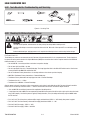
!
WARNING
Read and understand this entire Manual and your employer’s safety practices before install-
ing, operating, or servicing the equipment.
While the information contained in this Manual represents the Manufacturer's best judgement,
the Manufacturer assumes no liability for its use.
Plasma Cutting Power Supply
ESAB Fabricator
®
252i 3-in-1 Multi Process Welding Systems™
Operating Manual Number 0-5451
Published by:
ESAB
2800 Airport Rd.
Denton, TX 76208
www.esab.com
Copyright 2015 by ESAB
All rights reserved.
Reproduction of this work, in whole or in part, without written permission of the
publisher is prohibited.
The publisher does not assume and hereby disclaims any liability to any party for
any loss or damage caused by any error or omission in this Manual, whether such
error results from negligence, accident, or any other cause.
Original Publication Date: September 24, 2015
Revision Date:
Record the following information for Warranty purposes:
Where Purchased:_______________________________ __________
Purchase Date:__________________________________ __________
Power Supply Serial #:___________________________ __________
Torch Serial #:___________________________________ __________

Be sure this information reaches the operator.
You can get extra copies through your supplier.
CAUTION
These INSTRUCTIONS are for experienced operators. If you are not fully familiar
with the principles of operation and safe practices for arc welding and cutting equip-
ment, we urge you to read our booklet, “Precautions and Safe Practices for Arc
Welding, Cutting, and Gouging,” Form 52-529. Do NOT permit untrained persons to
install, operate, or maintain this equipment. Do NOT attempt to install or operate this
equipment until you have read and fully understand these instructions. If you do not
fully understand these instructions, contact your supplier for further information. Be
sure to read the Safety Precautions before installing or operating this equipment.
USER RESPONSIBILITY
This equipment will perform in conformity with the description thereof contained in this manual and accom-
panying labels and/or inserts when installed, operated, maintained and repaired in accordance with the instructions
provided. This equipment must be checked periodically. Malfunctioning or poorly maintained equipment should not be
used. Parts that are broken, missing, worn, distorted or contaminated should be replaced immediately. Should such re-
pair or replacement become necessary, the manufacturer recommends that a telephone or written request for service
advice be made to the Authorized Distributor from whom it was purchased.
This equipment or any of its parts should not be altered without the prior written approval of the manufacturer.
The user of this equipment shall have the sole responsibility for any malfunction which results from improper use,
faulty maintenance, damage, improper repair or alteration by anyone other than the manufacturer or a service facility
designated by the manufacturer.
!
READ AND UNDERSTAND THE INSTRUCTION MANUAL BEFORE INSTALLING OR
OPERATING.
PROTECT YOURSELF AND OTHERS!

TABLE OF CONTENTS
SECTION 1: SAFETY ........................................................................................ 1-1
1.0 Safety Precautions .......................................................................................... 1-1
SECTION 2: INTRODUCTION ............................................................................. 2-1
2.03 Receipt Of Equipment ..................................................................................... 2-1
2.04 Description ..................................................................................................... 2-1
2.01 How To Use This Manual ................................................................................ 2-1
2.02 Equipment Identification ................................................................................. 2-1
2.05 Symbol Chart .................................................................................................. 2-2
2.06 User Responsibility ......................................................................................... 2-3
2.07 Transportation Methods .................................................................................. 2-3
2.08 Packaged Items .............................................................................................. 2-3
2.09 Duty Cycle ....................................................................................................... 2-4
2.10 Specifications ................................................................................................. 2-5
SECTION 3: INSTALLATION OPERATION AND SETUP ................................................. 3-1
3.01 Environment ................................................................................................... 3-1
3.02 Location .......................................................................................................... 3-1
3.03 Ventilation ....................................................................................................... 3-1
3.04 Mains Supply Voltage Requirements .............................................................. 3-1
3.05 Electromagnetic Compatibility ........................................................................ 3-2
3.06 Power Source Controls, Indicators and Features ............................................ 3-3
3.07 Advanced Features Details .............................................................................. 3-8
3.08 Attaching the Tweco Fusion 250A MIG Gun .................................................. 3-13
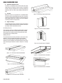
3.09 Installing a 12.5 lb spool (8" diameter) ......................................................... 3-14
3.10 Installing a Standard Spool (12" diameter) ................................................... 3-15
3.11 Inserting Wire into the Feed Mechanism ...................................................... 3-15
3.12 Feed Roller Pressure Adjustment .................................................................. 3-16
3.13 Feed Roller Alignment ................................................................................... 3-17
3.14 Changing the Feed Roll ................................................................................. 3-17
3.15 Input And Output Wire Guide Installation ..................................................... 3-18
3.16 Wire Reel Brake ............................................................................................ 3-19
3.17 Shielding Gas Regulator Operating Instructions ........................................... 3-20
3.18 Set-up MIG (GMAW) Welding with Gas Shielded MIG Wire .......................... 3-23
3.19 Set-up for MIG (FCAW) Welding with Gasless MIG Wire .............................. 3-24
3.20 Set-up for LIFT TIG (GTAW) Welding ............................................................ 3-25
3.21 Set-up for STICK Metal Arc Welding (SMAW) ............................................... 3-26
SECTION 4:
BASIC WELDING GUIDE ............................................................................ 4-1
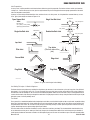
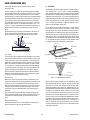
4.01 MIG (GMAW/FCAW) Basic Welding Technique ............................................... 4-1
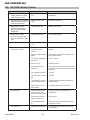
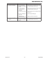
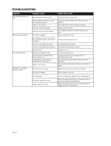
4.02 MIG (GMAW/FCAW) Welding Troubleshooting ............................................... 4-3
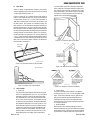
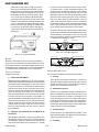
4.03 STICK (SMAW) Basic Welding Technique ....................................................... 4-5
4.04 STICK (SMAW) Welding Troubleshooting ..................................................... 4-12
4.05 TIG (GTAW) Basic Welding Technique .......................................................... 4-13
4.06 TIG (GTAW) Welding Problems ..................................................................... 4-16

TABLE OF CONTENTS
INTERNATIONAL CONTACT INFORMATION ................................................. REAR COVER
SECTION 5: theory of operation .......................................................................... 5-1
5.01 Theory of Operation Flow Chart ...................................................................... 5-1
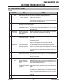
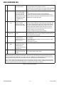
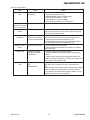
SECTION 6: Troubleshooting .............................................................................. 6-1
6.01 Power Source Problems ................................................................................. 6-1
6.02 Tools Needed for Troubleshooting and Servicing ............................................ 6-4
6.03 Checking Unit Before Applying Power ............................................................ 6-4
6.04 Routine Service and Calibration Requirements ............................................... 6-5
6.05 Dip Switch Settings for Calibration ................................................................. 6-6
6.06 Output Current / Amperage Calibration ........................................................... 6-8
6.07 Output Voltage Calibration .............................................................................. 6-9
6.08 Wire Speed Calibration ................................................................................. 6-10
6.09 Control Board Quick Check ........................................................................... 6-13
6.10 Case Removal ............................................................................................... 6-13
6.11 Visually Inspect ............................................................................................. 6-13
6.12 Preliminary check of the Main Power PCB .................................................... 6-13
6.13 Main Power Pcb Connector P12 / Control Pcb P2 Connector Signals .......... 6-17
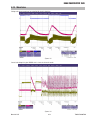
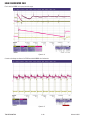
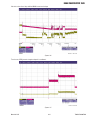
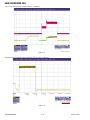
6.14 Waveforms ................................................................................................... 6-19
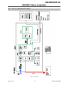
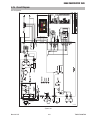
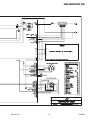
6.15 Circuit Diagram ............................................................................................. 6-23
6.16 Cleaning the Welding Power Source ............................................................. 6-24
6.17 Cleaning the Feed Rolls ................................................................................. 6-24
SECTION 7:
DISASSEMBLY PROCEDURE ....................................................................... 7-1
7.01 Safety Precautions for Disassembly ............................................................... 7-1
7.02 Control PCB (Operator Interface) Removal ..................................................... 7-1
7.03 Input Power Cord and Power Switch / Circuit Breaker Removal ..................... 7-3
7.04 MOV/Bridge PCB Removal .............................................................................. 7-4
7.05 High Speed (HS) Fan Shroud Removal .......................................................... 7-5
7.06 HS and LS Fan Removal ................................................................................. 7-6
7.07 Drive Motor Removal ...................................................................................... 7-7
7.08 Main Power PCB Removal .............................................................................. 7-8
SECTION 8: KEY SPARE PARTS .......................................................................... 8-1
8.01 Fabricator 252i Power Supply Replacement Panels ........................................ 8-1
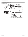
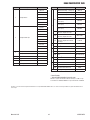
8.02 Tweco Fusion 250A MIG Gun .......................................................................... 8-4
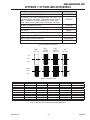
APPENDIX 1: OPTIONS AND ACCESSORIES ............................................................ A-1
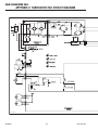
APPENDIX 2: FABRICATOR 252i CIRCUIT DIAGRAM .................................................. A-2
REVISION HISTORY ........................................................................................ A-4

ESAB FABRICATOR 252i
Manual 0-5451 1-1 SAFETY
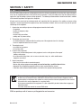
1.0 Safety Precautions
Users of ESAB welding and plasma cutting equipment have the ultimate responsibility for ensuring that anyone who works
on or near the equipment observes all the relevant safety precautions. Safety precautions must meet the requirements that
apply to this type of welding or plasma cutting equipment. The following recommendations should be observed in addition
to the standard regulations that apply to the workplace.
All work must be carried out by trained personnel well acquainted with the operation of the welding or plasma cutting
equipment. Incorrect operation of the equipment may lead to hazardous situations which can result in injury to the operator
and damage to the equipment.
1. Anyone who uses welding or plasma cutting equipment must be familiar with:
- its operation
- location of emergency stops
- its function
- relevant safety precautions
- welding and / or plasma cutting
2. The operator must ensure that:
- no unauthorized person stationed within the working area of the equipment when it is started up.
- no one is unprotected when the arc is struck.
3. The workplace must:
- be suitable for the purpose
- be free from drafts
4. Personal safety equipment:
- Always wear recommended personal safety equipment, such as safety glasses, flame proof
clothing, safety gloves.
- Do not wear loose fitting items, such as scarves, bracelets, rings, etc., which could become
trapped or cause burns.
5. General precautions:
- Make sure the return cable is connected securely.
- Work on high voltage equipment may only be carried out by a qualified electrician.
- Appropriate fire extinguishing equipment must be clearly marked and close at hand.
- Lubrication and maintenance must not be carried out on the equipment during operation.
Dispose of electronic equipment at the recycling facility!
In observance of European Directive 2002/96/EC on Waste Electrical and Electronic Equipment and its
implementation in accordance with national law, electrical and/or electronic equipment that has reached
the end of its life must be disposed of at a recycling facility.
As the person responsible for the equipment, it is your responsibility to obtain information on approved
collection stations.
For further information contact the nearest ESAB dealer.
ESAB can provide you with all necessary cutting protection and accessories.
SECTION 1: SAFETY

ESAB FABRICATOR 252i
SAFETY 1-2 Manual 0-5451
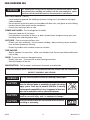
WARNING
Arc welding and cutting can be injurious to yourself and others. Take
precautions when welding and cutting. Ask for your employer's safety
practices which should be based on manufacturers' hazard data.
ELECTRIC SHOCK - Can kill.
- Install and earth (ground) the welding or plasma cutting unit in accordance with appli-
cable standards.
- Do not touch live electrical parts or electrodes with bare skin, wet gloves or wet clothing.
- Insulate yourself from earth and the workpiece.
- Ensure your working stance is safe.
FUMES AND GASES - Can be dangerous to health.
- Keep your head out of the fumes.
- Use ventilation, extraction at the arc, or both, to take fumes and gases away from your
breathing zone and the general area.
ARC RAYS - Can injure eyes and burn skin.
- Protect your eyes and body. Use the correct welding / plasma cutting screen and filter
lens and wear protective clothing.
- Protect bystanders with suitable screens or curtains.
FIRE HAZARD
- Sparks (spatter) can cause fire. Make sure therefore that there are no inflammable mate-
rials nearby.
NOISE - Excessive noise can damage hearing.
- Protect your ears. Use earmuffs or other hearing protection.
- Warn bystanders of the risk.
MALFUNCTION - Call for expert assistance in the event of malfunction.
READ AND UNDERSTAND THE INSTRUCTION MANUAL BEFORE INSTALLING OR OPERATING.
PROTECT YOURSELF AND OTHERS!
WARNING
Do not use the power source for thawing frozen pipes.
CAUTION
Class A equipment is not intended for use in residential locations
where the electrical power is provided by the public low-voltage
supply system. There may be potential difficulties in ensuring
electromagnetic compatibility of class A equipment in those loca-
tions, due to conducted as well as radiated disturbances.
CAUTION
This product is solely intended for metal removal. Any other use may
result in personal injury and / or equipment damage.
CAUTION
Read and understand the instruction manual before
installing or operating.
!

ESAB FABRICATOR 252i
Manual 0-5451 2-1 INTRODUCTION
SECTION 2: INTRODUCTION
2.03 Receipt Of Equipment
When you receive the equipment, check it against the invoice to
make sure it is complete and inspect the equipment for pos-
sible damage due to shipping. If there is any damage, notify the
carrier immediately to file a claim. Furnish complete information
concerning damage claims or shipping errors to the location in
your area listed in the inside back cover of this manual.
Include all equipment identification numbers as described above
along with a full description of the parts in error.
Move the equipment to the installation site before un-crating
the unit. Use care to avoid damaging the equipment when using
bars, hammers, etc., to un-crate the unit.
2.04 Description
The ESAB Fabricator 252i is a self contained single phase multi
process welding power source that is capable of performing
MIG (GMAW/FCAW), STICK (SMAW) and Lift TIG (GTAW) welding
processes. The Fabricator 252i is equipped with an integrated
wire feed unit, digital volt age / amperage meters, power factor
correction (PFC) with energy saving technology and a host of
other features to satisfy the broad operating needs of the modern
welding professional.
The Fabricator 252i is fully compliant to standard IEC 60974.1.
The Fabricator 252i MIG provides excellent welding performance
across a broad range of applications when used with the correct
welding consumables and procedures. The following instructions
detail how to correctly and safely set up the machine and give
guidelines on gaining the best efficiency and quality from the
Power Source. Please read these instructions thoroughly before
using the unit.
2.01 How To Use This Manual
This Owner’s Manual applies to just specification or part num-
bers listed on page i.
To ensure safe operation, read the entire manual, including the
chapter on safety instructions and warnings.
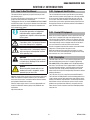
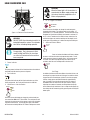
Throughout this manual, the words WARNING, CAUTION, DANGER,
and NOTE may appear. Pay particular attention to the information
provided under these headings. These special annotations are
easily recognized as follows:
NOTE!
An operation, procedure, or background
information which requires additional
emphasis or is helpful in efficient operation
of the system.
!
CAUTION
A procedure which, if not properly followed,
may cause damage to the equipment.
!
WARNING
A procedure which, if not properly followed,
may cause injury to the operator or others
in the operating area.
WARNING
Gives information regarding possible electri-
cal shock injury. Warnings will be enclosed
in a box such as this.
!
DANGER
Means immediate hazards which, if not
avoided, will result in immediate, serious
personal injury or loss of life.
Additional copies of this manual may be purchased by contacting
ESAB at the address and phone number in your area listed on
back cover of this manual. Include the Owner’s Manual number
and equipment identification numbers.
Electronic copies of this manual can also be downloaded at no
charge in Acrobat PDF format by going to the ESAB web site
listed below
http://www.esab.com
2.02 Equipment Identification
The unit’s identification number (specification or part number),
model, and serial number usually appear on a data tag attached
to the rear panel. Equipment which does not have a data tag
such as torch and cable assemblies are identified only by the
specification or part number printed on loosely attached card or
the shipping container. Record these numbers on the bottom of
page i for future reference.

ESAB FABRICATOR 252i
INTRODUCTION 2-2 Manual 0-5451
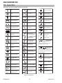
2.05 Symbol Chart
Note that only some of these symbols will appear on your model.
Gas Tungsten Arc
Welding (GTAW)
Air Carbon Arc
Cutting (CAC-A)
Constant Current
Constant Voltage
Or Constant Potential
High Temperature
Fault Indication
Arc Force
Touch Start (GTAW)
Variable Inductance
Voltage Input
Single Phase
Three Phase
Three Phase Static
Frequency Converter-
Transformer-Rectifier
Dangerous Voltage
OFF
ON
Panel/Local
Shielded Metal
Arc Welding (SMAW)
Gas Metal Arc
Welding (GMAW)
Increase/Decrease
Circuit Breaker
AC Auxiliary Power
Remote
Duty Cycle
Percentage
Amperage
Voltage
Hertz (cycles/sec)
Frequency
Negative
Positive
Direct Current (DC)
Protective Earth
(Ground)
Line
Line Connection
Auxiliary Power
Receptacle Rating-
Auxiliary Power
Art # A-10663_AB
115V 15A
t
t1
t2
%
X
IPM
MPM
t
V
Fuse
Wire Feed Function
Wire Feed Towards
Workpiece With
Output Voltage OFF.
Preflow Time
Postflow Time
Spot Time
Spot Weld Mode
Continuous Weld
Mode
Press to initiate wirefeed and
welding, release to stop.
Purging Of Gas
Inches Per Minute
Meters Per Minute
Welding Gun
Burnback Time
Press and hold for preflow, release
to start arc. Press to stop arc, and
hold for preflow.
4 Step Trigger
Operation
2 Step Trigger
Operation
S
See Note
See Note
Pulse Welding
Figure 2-1: Symbol chart

ESAB FABRICATOR 252i
Manual 0-5451 2-3 INTRODUCTION
2.06 User Responsibility
This equipment will perform as per the information contained
herein when installed, operated, maintained and repaired in
accordance with the instructions provided. This equipment must
be checked periodically. Defective equipment (including welding
leads) should not be used. Parts that are broken, missing, plainly
worn, distorted or contaminated, should be replaced immediately.
Should such repairs or replacements become necessary, it is
recommended that such repairs be carried out by appropriately
qualified persons approved by ESAB. Advice in this regard can be
obtained by contacting an Accredited ESAB Distributor.
This equipment or any of its parts should not be altered from
standard specification without prior written approval of ESAB.
The user of this equipment shall have the sole responsibility for
any malfunction which results from improper use or unauthorized
modification from standard specification, faulty maintenance,
damage or improper repair by anyone other than appropriately
qualified persons approved by ESAB.
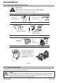
2.07 Transportation Methods
WARNING
ELECTRIC SHOCK can kill. DO NOT TOUCH
live electrical parts. Disconnect input power
conductors from de-energized supply line
before moving the welding power source..
!
WARNING
FALLING EQUIPMENT can cause serious
personal injury and equipment damage.
Lift unit with integrated hand holds at the front and rear of the
unit.
Use handcart or similar device of adequate capacity.
If using a fork lift vehicle, place and secure unit on a proper skid
before transporting.
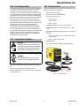
2.08 Packaged Items
Fabricator 252i Part No. (W1004401)
- Fabricator 252i Power Supply
- 15 ft Tweco
®
Fusion 250 Amp MIG Gun
- Velocity Contact tips (1 each)
• .030" (0.8 mm)
• .035" (0.9 mm)
• .045" (1.2 mm)
- Victor® Argon Regulator / Gauge & 10 ft. (3M) Hose
- ESAB WeldSkill 200 Amp electrode holder with 13 ft. (4 M)
lead
- ESAB WeldSkill 200 Amp ground clamp with 10 ft. (3 M) lead
- Drive Rolls:
• .035" / .045" (0.9 to 1.2 mm) V Grooved Lower & Flat
Upper (Fitted)
• .045" (1.2 mm) Flux Cored Roll
- Operating Manual
- 9 ft. (2.75 M) Power cord & NEMA 6-50P 230V AC Plug
A-12953
Figure 2-2: Packaged Items

ESAB FABRICATOR 252i
INTRODUCTION 2-4 Manual 0-5451
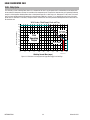
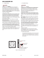
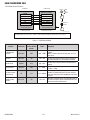
2.09 Duty Cycle
The rated duty cycle of a Welding Power Source is a statement of the time it may be operated at its rated welding current output with-
out exceeding the temperature limits of the insulation of the component parts. To explain the 10 minute duty cycle period the following
example is used. Suppose a Welding Power Source is designed to operate at a 40% duty cycle, 250 amperes at 26.5 volts. This means
that it has been designed and built to provide the rated amperage (250A) for 4 minutes, i.e. arc welding time, out of every 10 minute
period (40% of 10 minutes is 4 minutes). During the other 6 minutes of the 10 minute period the Welding Power Source must idle and
be allowed to cool.
Art # A-10666
Duty Cycle (percentage)
0
25 50 75
80
100
125 150 225 250
30
50
70
90
40
60
20
10
100
0
Welding Current Max (amps)
STICK (SMAW)
TIG (GTAW)
MIG (GMAW)
175
200
With Factory Fitted Supply Cord and Plug
Safe
Operating
Region
Figure 2-3: Fabricator 252i Duty Cycle with Upgraded Supply Lead and Plug

ESAB FABRICATOR 252i
Manual 0-5451 2-5 INTRODUCTION
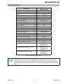
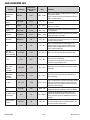
2.10 Specifications
Description
Fabricator 252i MULTI PROCESS
WELDING INVERTER
Power Source Dimensions H 17.5" x W 10.25" x D 23.5"
Power Source Mass 65 lbs.
Cooling Fan Cooled
Welder Type Multi Process Power Source
Standard IEC60974.1
Number of Phases Single Phase
Nominal Supply Voltage 208/230 VAC ± 15%
Supply Voltage Range 187 - 265 VAC
Nominal Supply Frequency 50/60Hz
Open Circuit Voltage 72 VDC
MIG Voltage Range 14-30 VDC
Wirefeeder Speed Range 67 - 700 ipm (1.7 - 17.8 M/min.)
Protection Class IP23S
Supply Lead & Plug Rating 50 Amps (10 AWG)
Welding Current Range (MIG Mode) 20-300 Amps
Welding Current Range (LIFT TIG Mode) 5-300 Amps
Welding Current Range (STICK Mode) 20-230 Amps
Effective Input Current (I1eff) 22.4 Amps
Maximum Input Current (I1max) 34.7 Amps
Single Phase Generator Requirement 10 kVA
MIG (GMAW) Welding Output, 40°C, 10 min. 250A @ 40%,26.5V
200A @ 60%, 24V
150A @ 100%, 21.5V
STICK (SMAW) Welding Output, 40°C, 10 min. 230A @ 40%,29.2V
200A @ 60%, 28V
150A @ 100%, 26V
TIG (GTAW) Welding Output, 40°C, 10 min. 250A @ 40%,20V
200A @ 60%, 18V
150A @ 100%, 16V
Table 2-1: Fabricator 252i Specification
NOTE!
Due to variations that can occur in manufactured products, claimed performance, voltages, ratings, all
capacities, measurements, dimensions and weights quoted are approximate only. Achievable capacities
and ratings in use and operation will depend upon correct installation, use, applications, maintenance and
service.

ESAB FABRICATOR 252i
INTRODUCTION 2-6 Manual 0-5451
This Page Intentionally Blank

ESAB FABRICATOR 252i
Manual 0-5451 3-1 INSTALLATION
3.01 Environment
This unit is designed for use in environments with increased
hazard of electric shock as outlined in IEC 60974.1. Additional
safety precautions may be required when using unit in an
environment with increased hazard of electric shock. Please refer
to relevant local standards for further information prior to using in
such areas.
A. Examples of environments with increased hazard of electric
shock are:
1. In locations in which freedom of movement is restricted,
so that the operator is forced to perform the work in a
cramped (kneeling, sitting or lying) position with physi-
cal contact with conductive parts.
2. In locations which are fully or partially limited by con-
ductive elements, and in which there is a high risk of
unavoidable or accidental contact by the operator.
3. In wet or damp hot locations where humidity or perspi-
ration considerably reduces the skin resistance of the
human body and the insulation properties of accesso-
ries.
B. Environments with increased hazard of electric shock
do not include places where electrically conductive parts in the
near vicinity of the operator, which can cause increased hazard,
have been insulated.
3.02 Location
Be sure to locate the welder according to the following guide-
lines:
A. In areas, free from moisture and dust.
B. Ambient temperature between 32° F to 104° F.
C. In areas, free from oil, steam and corrosive gases.
D. In areas, not subjected to abnormal vibration or shock.
E. In areas, not exposed to direct sunlight or rain.
F. Place at a distance of 1 foot or more from walls or similar
that could restrict natural air flow for cooling.
G. The enclosure design of this power source meets the re-
quirements of IP23S as outlined in IEC60529.
H. Precautions must be taken against the power source top-
pling over. The power source must be located on a suitable
horizontal surface in the upright position when in use.
WARNING
This equipment should be electrically con-
nected by a qualified electrician..
SECTION 3: INSTALLATION OPERATION AND SETUP
3.03 Ventilation
!
WARNING
Since the inhalation of welding fumes can
be harmful, ensure that the welding area is
effectively ventilated..
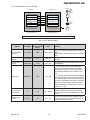
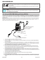
3.04 Mains Supply Voltage
Requirements
!
CAUTION
The Mains supply voltage should be within
± 15% of the rated Mains supply voltage.
Too low of a supply voltage may cause poor
welding performance or wirefeeder mal-
function. Too high of a supply voltage will
cause components to overheat and possibly
fail.
WARNING
The Fabricator 252i must be electrically
connected by a qualified electrical trades-
person. Damage to the PCA (Power Control
Assembly) could occur if 276 VAC or higher
is applied to the Primary Power Cable.

ESAB FABRICATOR 252i
INSTALLATION 3-2 Manual 0-5451
50/60 Hz
Single Phase
Primary Supply
Lead Size
Minimum Primary
Current Circuit
Size (Vin/Iin)
Minimum
Plug and
Breaker
Size
Current & Duty Cycle
MIG LIFT TIG STICK
Yes 10 AWG 208-230/50A 50A 40% @ 250A 40% @ 250A 40% @ 230A
Table 3-1: Input Power Source Leads for Fabricator 252i
WARNING
ELECTRIC SHOCK can kill; SIGNIFICANT DC
VOLTAGE is present after removal of input
power. DO NOT TOUCH live electrical parts.
SHUT DOWN welding power source, disconnect input power em-
ploying lockout/tagging procedures. Lock-out/tagging procedures
consist of padlocking line disconnect switch in open position,
removing fuses from fuse box, or shutting OFF and red-tagging
circuit breaker or other disconnecting device.
Electrical Input Requirements
Operate the welding power source from a single-phase 50/60 Hz,
AC power source. The Welding Power Source must be:
• Correctly installed, if necessary, by a qualied electrician.
• Correctly earthed (electrically) in accordance with local
regulations.
• Connected to the correct size power point, fuse and primary
supply lead based on Table 3-1.
WARNING
Any electrical work must be carried out by a
qualified Electrical Tradesperson.
3.05 Electromagnetic Compatibility
!
WARNING
Extra precautions for Electromagnetic
Compatibility may be required when this
Welding Power Source is used in a domes-
tic situation.
A. Installation and Use - Users Responsibility
The user is responsible for installing and using the welding
equipment according to the manufacturer’s instructions. If
electromagnetic disturbances are detected then it shall be the
responsibility of the user of the welding equipment to resolve the
situation with the technical assistance of the manufacturer. In
some cases this remedial action may be as simple as earthing
the welding circuit, see NOTE below. In other cases it could
involve constructing an electromagnetic screen enclosing the
Welding Power Source and the work, complete with associated
input filters. In all cases, electromagnetic disturbances shall be
reduced to the point where they are no longer Troublesome.
NOTE!
The welding circuit may or may not be
earthed for safety reasons. Changing the
earthing arrangements should only be
authorized by a person who is competent to
assess whether the changes will increase
the risk of injury, e.g. by allowing parallel
welding current return paths which may
damage the earth circuits of other equip-
ment. Further guidance is given in IEC
60974-13 Arc Welding Equipment - Installa-
tion and use (under preparation).
B. Assessment of Area
Before installing welding equipment, the user shall make
an assessment of potential electromagnetic problems in the
surrounding area. The following shall be taken into account.
1. Other supply cables, control cables, signaling and telephone
cables; above, below and adjacent to the welding equipment.
2. Radio and television transmitters and receivers.
3. Computer and other control equipment.
4. Safety critical equipment, e.g. guarding of industrial
equipment.
5. The health of people around, e.g. the use of pace-makers
and hearing aids.
6. Equipment used for calibration and measurement.
7. The time of day that welding or other activities are to be
carried out.
8. The immunity of other equipment in the environment: the
user shall ensure that other equipment being used in the
environment is compatible: this may require additional
protection measures.
The size of the surrounding area to be considered will depend on
the structure of the building and other activities that are taking
place. The surrounding area may extend beyond the boundaries
of the premises.
C. Methods of Reducing Electromagnetic Emissions
1. Mains Supply
Welding equipment should be connected to the mains
supply according to the manufacturer’s recommendations.
If interference occurs, it may be necessary to take
additional precautions such as filtering of the mains supply.
Consideration should be given to shielding the supply cable
of permanently installed welding equipment in metallic
conduit or equivalent. Shielding should be electrically
continuous throughout its length. The shielding should be

ESAB FABRICATOR 252i
Manual 0-5451 3-3 INSTALLATION
connected to the Welding Power Source so that good electrical contact is maintained between the conduit and the Welding
Power Source enclosure.
2. Maintenance of Welding Equipment
The welding equipment should be routinely maintained according to the manufacturer’s recommendations. All access and
service doors and covers should be closed and properly fastened when the welding equipment is in operation. The welding
equipment should not be modified in any way except for those changes and adjustments covered in the manufacturer’s
instructions.
3. Welding Cables
The welding cables should be kept as short as possible and should be positioned close together but never coiled and running
at or close to the floor level.
4. Equipotential Bonding
Bonding of all metallic components in the welding installation and adjacent to it should be considered. However, metallic
components bonded to the work piece will increase the risk that the operator could receive a shock by touching the metallic
components and the electrode at the same time. The operator should be insulated from all such bonded metallic components.
5. Earthing/grounding of the Work Piece
Where the work piece is not bonded to earth for electrical safety, nor connected to earth because of its size and position, e.g.
ship’s hull or building steelwork, a connection bonding the work piece to earth may reduce emissions in some, but not all
instances. Care should be taken to prevent the earthing of the work piece increasing the risk of injury to users, or damage to
other electrical equipment. Where necessary, the connection of the work piece to earth should be made by direct connection
to the work piece, but in some countries where direct connection is not permitted, the bonding should be achieved by suitable
capacitance, selected according to national regulations.
6. Screening and Shielding
Selective screening and shielding of other cables and equipment in the surrounding area may alleviate problems of interference.
Screening the entire welding installation may be considered for special applications.
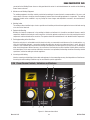
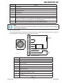
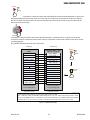
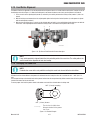
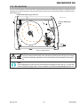
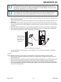
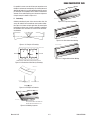
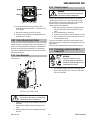
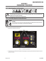
3.06 Power Source Controls, Indicators and Features
1
2
3
4
5
7
9
8
6
A-12927
Figure 3-1: Fabricator Control Panel

ESAB FABRICATOR 252i
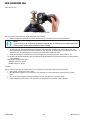
INSTALLATION 3-4 Manual 0-5451
+
-
11
12
13 14
15
Art # A-10504
10
Figure 3-2: Fabricator Front Connections
WARNING
DO NOT TOUCH the electrode wire while it is
being fed through the system. The electrode
wire will be at welding voltage potential.
NOTE!
Fan operation_ Fan is always on in Stick
mode. For Mig and TIG the fan is on from
arc strike to 10 minutes after the weld has
been completed.
1. Power Indicator
The green power indicator will be illuminated when the welder is
turned ON and indicates the presence of power.
2. Fault Indicator
The yellow fault indicator will be illuminated when any of the
faults are detected. ALL Faults will illuminate the indicator
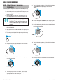
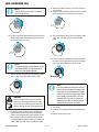
3. Weld Process Selection Button
TIG
Process
MIG
STICK
Press and release this button to change the selected weld pro-
cess mode from MIG to LIFT TIG to STICK. The weld process will
change to the next process in the sequence each time the button
is pressed and released. The red indicators next to the button
will illuminate to identify MIG or LIFT TIG or STICK process mode.
WARNING
When the Power light is lit, the machine is
connected to the Mains supply voltage and
the internal electrical components are at
Mains voltage potential.
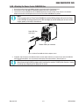
4. 2T - 4T Trigger Latch Button
Trigger
2T Normal
4T Latch
Press and release the button to change the selected operat-
ing mode of the trigger. The selected mode can be either “2T”
(unlatched) or “4T” (latched) operation. The red indicator next to
the button will illuminate to identify which mode is selected (2T
or 4T). In the 4T mode once the weld has been started you can
release the trigger and continue welding until the trigger is acti-
vated again or the welding arc is broken to stop the welding arc.
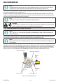
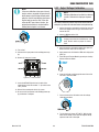
5. Advanced Features Button
Advanced
Features
Press and release the Advanced Features button
to enter or exit from the advanced programming mode. To exit,
simply press and release the button again. Any changes made
are saved. The advanced programming menu items are de-
scribed in detail for each welding mode in Section 3.07.
Advanced
Features
Gas Purge.
In addition, the Advanced Features Button is used to initiate a 30
second gas line purge function to fill the gas line with the shield-
ing gas from the connected gas cylinder. To start the gas purge
function, simply press and hold the button for approximately
two (2) seconds. Once the Gas purge function has started, a
countdown timer will show in the left alpha-numeric display
indicating the number of seconds remaining before the purge
will be automatically terminated. You can stop the Gas purge any
time during the 30 seconds by quickly pressing and releasing the
button again.

ESAB FABRICATOR 252i
Manual 0-5451 3-5 INSTALLATION
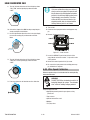
6. Left Knob: Amperage Control (Wirespeed)
WIRESPEED
A
Left Knob
The amperage control knob adjusts the amount of welding cur-
rent delivered by the power source. In STICK and LIFT TIG modes,
the amperage control knob directly adjusts the power inverter
to deliver the desired level of output current. In MIG mode, the
amperage knob adjusts the speed of the wire feed motor (which
in turn adjusts the output current by varying the amount of MIG
wire delivered to the welding arc). The optimum wire speed re-
quired is dependent on the type of welding application. The setup
chart on the inside of the wire feed compartment door provides
a brief summary of the required output settings for a basic range
of MIG welding applications. The value may also be adjusted
while a weld is in progress – if this occurs, the left display will
briefly switch to show the adjusted value as the knob is turned,
and will automatically revert back to showing the weld current
measurements when the knob is not being turned.
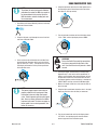
7. Right Knob: Multifunction Control - MIG Voltage / Arc
Control (Inductance) & STICK Arc Force
ARC CONTROL
V
Right Knob
MIG Voltage Control
In this mode the control knob is used to adjust the output volt-
age of the power source. The welding voltage is increased by
turning the knob clockwise or decreased by turning the knob
anti-clockwise. The optimum voltage level required is dependent
on the type of welding application. The setup chart on the inside
of the wire feed compartment door provides a brief summary
of the required output settings for a basic range of MIG welding
applications. The value may also be adjusted while a weld is in
progress – if this occurs, the left display will briefly switch to
show the adjusted value as the knob is turned, and will auto-
matically revert back to showing the weld current measurements
when the knob is not being turned.
ARC CONTROL
V
Right Knob
Right Knob
MIG Arc Control (Inductance)
The arc control operates in MIG mode only and is used to adjust
the intensity of the welding arc. To access the Arc Control func-
tion, push inward on the right knob and hold it for approximately
2 seconds. This feature can be accessed and adjusted during
welding.
When STICK Mode is Selected
In this mode the multifunction control knob is used to adjust arc
force. Arc force control provides an adjustable amount of welding
force (or “dig”) control. This feature can be particularly beneficial
in providing the operator the ability to compensate for variability
in joint fit-up in certain situations with particular electrodes. In
general increasing the arc force control toward ‘100%’ (maxi-
mum arc force) allows greater penetration control to be achieved.
Arc force is increased by turning the control knob clockwise or
decreased by turning the knob anti-clockwise. This feature can
be accessed and adjusted during welding.
To access the Arc Control function, push inward on the right knob
and hold it for approximately 2 seconds. This feature can be ac-
cessed and adjusted during welding.
The left display will change to show the Arc Control parameter
name that is in effect for the current MIG or STICK Modes and
the right display will show its present value. Use the right knob
to change the value. When the desired value is selected, press
inward again on the knob without turning it and release it to exit
the Arc Control function and save the value.
Weld Modes Arc Control Function Left Display Right Display Limits
MIG Inductance INDU 25% (default) 0 – 100 %
STICK Arc Force ARC- / FRCE 50% (default) 0 – 100%
Table 3-2

ESAB FABRICATOR 252i
INSTALLATION 3-6 Manual 0-5451
8. Left Digital Display
MIG Mode
This digital meter is used to display the pre-set (preview)
Wirefeed Speed in Inches Per Minute (IPM) in MIG mode and
actual welding amperage of the power source when welding.
At times of non-welding, the digital meter will display a pre-set
(preview) value of Wirefeed Speed. This value can be adjusted by
varying the Left Knob (Control No 6).
STICK and LIFT TIG Modes
The digital meter is used to display the pre-set (preview) amper-
age in STICK / LIFT TIG modes and actual welding amperage of
the power source when welding. At times of non-welding, the
amperage meter will display a pre-set (preview) value in both
STICK and LIFT TIG modes. This value can be adjusted by varying
the Left Knob (Control No 6).
When welding, this digital meter will display actual welding
amperage in all modes.
At the completion of welding, the digital meter will hold the last
recorded amperage value for a period of approximately 10 sec-
onds in all modes. The amperage meter will hold the value until;
(1) any of the front panel controls are adjusted in which case the
unit will revert to preview mode, (2) welding is recommenced, in
which case actual welding amperage will be displayed, or (3) a
period of 10 seconds elapses following the completion of welding
in which case the unit will return to preview mode.
The display is also used for providing error messages to the user
and showing other information, which will be explained in Sec-
tion 5.
9. Right Digital Display
MIG Mode
This digital meter is used to display the pre-set (preview) Voltage
in MIG mode and actual welding voltage of the power source
when welding. At times of non-welding, the digital meter will
display a pre-set (preview) value of Voltage. This value can be
adjusted by varying the Right Knob (Control No 7).
STICK and LIFT TIG Modes
This digital meter is used to display the Welding Output Terminal
Voltage in STICK / LIFT TIG modes during non-welding or welding.
This value can not be adjusted by varying the Right Knob (Control
No 7).
When welding, this digital meter will display actual welding volt-
age in all modes.
At the completion of welding, the digital meter will hold the last
recorded voltage value for a period of approximately 10 seconds
in all modes. The voltage meter will hold the value until; (1) any
of the front panel controls are adjusted in which case the unit will
revert to preview mode, (2) welding is recommenced, in which
case actual welding amperage will be displayed, or (3) a period
of 10 seconds elapses following the completion of welding in
which case the unit will return to preview mode.
The display is also used for providing error messages to the user
and showing other information, which will be explained in Sec-
tion 5.
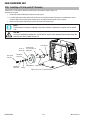
10. MIG Gun Adaptor
The MIG Gun Adapter is the connection point for the Tweco
Fusion 250A MIG Gun. Refer to section 3.08 for the correct pro-
cedure for attaching the Tweco Fusion 250A MIG Gun.
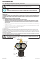
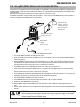
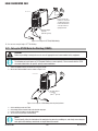
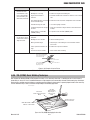
11. Remote Control Socket
The 8 pin Remote Control Socket is used to connect remote
control devices to the welding power source. To make con-
nections, align keyway, insert plug, and rotate threaded collar
fully clockwise.
2
1
8
7
6
3
4
5
Trigger Switch
Remote Wirespeed in GMAW mode
Remote Amps in GTAW mode
Remote Volts in
GMAW Mode
1
2
3
4
5
6
7
8
W
V
A-09594_AC
Figure 3-3: Remote Control Socket
Page is loading ...
Page is loading ...
Page is loading ...
Page is loading ...
Page is loading ...
Page is loading ...
Page is loading ...
Page is loading ...
Page is loading ...
Page is loading ...
Page is loading ...
Page is loading ...
Page is loading ...
Page is loading ...
Page is loading ...
Page is loading ...
Page is loading ...
Page is loading ...
Page is loading ...
Page is loading ...
Page is loading ...
Page is loading ...
Page is loading ...
Page is loading ...
Page is loading ...
Page is loading ...
Page is loading ...
Page is loading ...
Page is loading ...
Page is loading ...
Page is loading ...
Page is loading ...
Page is loading ...
Page is loading ...
Page is loading ...
Page is loading ...
Page is loading ...
Page is loading ...
Page is loading ...
Page is loading ...
Page is loading ...
Page is loading ...
Page is loading ...
Page is loading ...
Page is loading ...
Page is loading ...
Page is loading ...
Page is loading ...
Page is loading ...
Page is loading ...
Page is loading ...
Page is loading ...
Page is loading ...
Page is loading ...
Page is loading ...
Page is loading ...
Page is loading ...
Page is loading ...
Page is loading ...
Page is loading ...
Page is loading ...
Page is loading ...
Page is loading ...
Page is loading ...
Page is loading ...
Page is loading ...
Page is loading ...
Page is loading ...
Page is loading ...
Page is loading ...
Page is loading ...
Page is loading ...
Page is loading ...
Page is loading ...
Page is loading ...
Page is loading ...
Page is loading ...
Page is loading ...
Page is loading ...
Page is loading ...
Page is loading ...
Page is loading ...
Page is loading ...
Page is loading ...
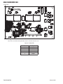
-
 1
1
-
 2
2
-
 3
3
-
 4
4
-
 5
5
-
 6
6
-
 7
7
-
 8
8
-
 9
9
-
 10
10
-
 11
11
-
 12
12
-
 13
13
-
 14
14
-
 15
15
-
 16
16
-
 17
17
-
 18
18
-
 19
19
-
 20
20
-
 21
21
-
 22
22
-
 23
23
-
 24
24
-
 25
25
-
 26
26
-
 27
27
-
 28
28
-
 29
29
-
 30
30
-
 31
31
-
 32
32
-
 33
33
-
 34
34
-
 35
35
-
 36
36
-
 37
37
-
 38
38
-
 39
39
-
 40
40
-
 41
41
-
 42
42
-
 43
43
-
 44
44
-
 45
45
-
 46
46
-
 47
47
-
 48
48
-
 49
49
-
 50
50
-
 51
51
-
 52
52
-
 53
53
-
 54
54
-
 55
55
-
 56
56
-
 57
57
-
 58
58
-
 59
59
-
 60
60
-
 61
61
-
 62
62
-
 63
63
-
 64
64
-
 65
65
-
 66
66
-
 67
67
-
 68
68
-
 69
69
-
 70
70
-
 71
71
-
 72
72
-
 73
73
-
 74
74
-
 75
75
-
 76
76
-
 77
77
-
 78
78
-
 79
79
-
 80
80
-
 81
81
-
 82
82
-
 83
83
-
 84
84
-
 85
85
-
 86
86
-
 87
87
-
 88
88
-
 89
89
-
 90
90
-
 91
91
-
 92
92
-
 93
93
-
 94
94
-
 95
95
-
 96
96
-
 97
97
-
 98
98
-
 99
99
-
 100
100
-
 101
101
-
 102
102
-
 103
103
-
 104
104


ESAB ESAB Fabricator® 252i 3-IN-1 Multi Process Welding Systems User manual
- Category
- Welding System
- Type
- User manual
Ask a question and I''ll find the answer in the document
Finding information in a document is now easier with AI
Related papers
-
ESAB ESAB Fabricator® 252i 3-IN-1 Multi Process Welding Systems User manual
-
-
ESAB 252i® FABRICATOR User manual
-
-
ESAB FABRICATOR®252i User manual
-
-
-
-
-
Other documents
-
 HIT Welding 802030 User guide
-
Ross RXT200EX Instructions Manual
-
 Tweco FABRICATOR 252i Operating instructions
-
 METAL MAN 200iDV ACDC User manual
-
 WELDTECH WT160MP Operating
-
 HIT Welding 802283 User guide
-
Campbell Hausfeld WF2010 User manual
-
-
-
 Oxford MIGMAKER Series User manual


