Briteq MICRO BEAMER RGBW Owner's manual
- Category
- Stroboscopes & disco lights
- Type
- Owner's manual


3.6--DMX512 SETTINGS..................................................................... 7.
PART 4 USING A DMX512 CONTROLLER.....................................9.
4.1--BASIC ADDRESSING................................................................. 9.
4.2--CHANNEL ASSIGNMENT.............................................................9.
PART 3 DISPLAY PANEL OPERATION.........................................5.
3.1--BASIC................................................................................... ......5.
3.2--MENU......................................................................................... 5.
3.4--ACTIVATING AUTO PROGRAMS.................................................. 6.
3.7--PERSONALITY............................................................................ 7 .
3.8--SPECIAL SETTINGS.................................................................. . 7.
3.9--A CTIVATE THE PASSWORD ...................................................... .8.
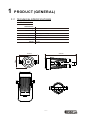
PART 1 PRODUCT (GENERAL)....................................................1.
1.1 TECHNICAL SPECIFICATIONS-- .....................................................1.
1.2 SAFETY WARNING-- ......................................................................2.
PART 2 INSTALLATION...............................................................3.
2.1--MOUNTING...................................................................................3.
2.2--SIGNAL CONNECTIONS.......................................................... .....3.
3.3--EDIT STATIC COLOUR................................................................ 6 .
PART 5 APPENDIX......................................................................13.
5.1--MAINTENANCE......................................................................... 13.
3.5--RUN MODE................................................................................ . 6.
3.10--BALANCE PARAMETERS AND CORRECTION MENU DISPLAY.....8.
ABLE OF CONTENTS
T
2.3--SETTING UP WITH A DMX512 CONTROLLER(STAGE 1 MODE) .....4.


·2·
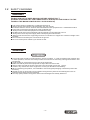
1.2 SAFETY WARNING
IMPORTANT
【ALWAYS READ THE USER MANUAL BEFORE OPERATION. 】
【PLEASE CONFIRM THAT THE POWER SUPPLY STATED ON THE PRODUCT IS THE
SAME AS THE MAINS POWER SUPPLY IN YOUR AREA.】
● This product must be installed by a qualified professional.
● Always operate the equipment as described in the user manual.
●A minimum distance of 0.5m must be maintained between the equipment and combustible surface.
● The product must always be placed in a well ventilated area.
● Always make sure that the equipment is installed securely.
● DO NOT stand close to the equipment and stare directly into the LED light source.
● Always disconnect the power supply before attempting and maintenance.
● Always make sure that the supporting structure is solid and can support the combined weight of the
products.
● The earth wire must always be connected to the ground.
● Do not touch the power cables if your hands are wet.
ATTENTION
● This product left the place of manufacture in perfect condition. In order to maintain this condition and
for safe operation, the user must always follow the instructions and safety warnings described in this
user manual.
● Avoid shaking or strong impacts to any part of the equipment.
● Make sure that all parts of the equipment are kept clean and free of dust.
● Always make sure that the power connections are connected correct and secure.
● If there is any malfunction of the equipment, contact your distributor immediately.
● When transferring the product, it is advisable to use the original packaging in which the product left
the factory.
● Shields, lenses or ultraviolet screens shall be changed if they have become damaged to such an
extent that their effectiveness is impaired.
● The lamp (LED) shall be changed if it has become damaged or thermally deformed.

·3·
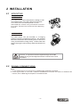
2.1 MOUNTING
UPRIGHT
2 INSTALLATION
The LED Fixture can be mounted in a sitting or wall
mounted position using the supporting brackets.
The LED Fixture should be placed on a non-
flammable flat surface in any orientation and fixed
by screws. There are four holes into the supporting
bracket.
The LED can be mounted in a hanging
position using the supporting bracket. The bracket
should be secured to the mounting truss or structure
using a standard mounting clamp. Please note that
when hanging the unit a safety cable should also be
used.
fixture
The LED MODULE can be mounted at any angle and in any
position. It is possible to further adjust the angle of the LED
MODULE using the two adjustment knobs located on the side of
the fixture.
HANGING
2.2 SIGNAL CONNECTIONS
Note:
1. If over 25units to be connected, then a DMX signal amplifier is needed.
2. If the signal cable is over 60m between the DMX512 controller and fixture or beween two
fixtures, then a DMX signal amplifier is needed as well.

·4·
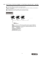
2.3 SETTING UP WITH A DMX512 CONTROLLER(STAGE 1 MODE)
The figure above shows a simple DMX512
layout with the starting address of the first
unit set at 1, with the second set at 10 and
so on...
DMX512
CONTROLLER
●
● Each unit has 9 DMX channels so the DMX Addresses should increase by increments of
9 (e.g. 1,10,19,28...)
● Each DMX Address may be used as many times as required.
● Any DMX address in the range from 001 to 512 may be used.
Connect the DMX512 controller to the units in series.
Example:
............
DMX Addr.1 DMX Addr.10 DMX Addr.19

UP
DOWN
ENTER
RUN 512
SLA
(001~512)
ADD
A.01
A.02
A.10
AUT
ENTER
RED
GRN
BLU
YTE
(0~255)
(0~255)
(0~255)
(0~255)
STR
(0~20)
STA
TOR
A1
A.2
A1.D
A2.S
A2.D
PER
HSU
OUT
SET
UPL
COL
UC
OFF
RST
1
3
2
4
DIN
OFF
YES
END
DRR
SAU
BLA
OUT
RGB
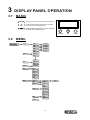
3.1 BASIC
scroll 'UP' through the menu list or increase
the value of the current function
scroll 'DOWN' through the menu list or decrease
the value of the current function
Choose one or retum to the previous menu
ENTER
3.2 MENU
3 DISPLAY PANEL OPERATION
·5·

·6·
LOC ON
OFF
Y.01
Y.02
Y.11
RED
GRN
BLU
YTE
(0~255)
(0~255)
(0~255)
(0~255)
CAL
RGB
RED
GRN
BLU
(0~255)
(0~255)
(0~255)
OUT
YTE
(0~255)
OUT
YTE
OUT
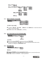
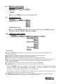
3.4 ACTIVATING AUTO PROGRAMS
【AUTO】
● Select the target【AUT】 program and press【ENTER】.
● Programs【A.01】to【A.10】are fully pre-programmed and will not be
altered by changes in【ENTER】mode.
3.3 EDIT STATIC COLOUR
【STATIC COLOUR】
● Combine 【Red】, 【Green】, 【Blue】 and 【White】 to create an infinite
range of colors (0-255)
● Set the value of the 【Strobe】 (0-20Hz)
【RUN 】
● Enter the【RUN 】mode to set working mode.
● 【DMX】 mode is for using the DMX512 controller to control the fixtures.
● 【SLA】 mode is for Master -- Slave operation.
3.5 RUN MODE
(0~255)
(0~255)
(0~255)
(0~255)
(0~20)
ENTER
RED
GRN
BLU
YTE
STR
STA
A.01
A.02
A.10
AUT
ENTER
RUN 512
SLA
ENTER

·7·
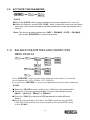
3.7 PERSONALITY
【PERSONALITY】
● Enter the【PERSONALITY】mode to select DMX mode:【TOUR】,【A1】,
【A1.D】,【A.2】,【A2.D】,【A2.S】,【HSU】.
3.6 DMX512 SETTINGS
【DMX】
● Enter the【DMX】mode to set the DMX ADD.
ADD
ENTER
(001~512)
ENTER
TOR
A1
A.2
A1.D
A2.S
A2.D
PER
HSU
3.8 SPECIAL SETTINGS
ENTER
【SETTING】
● Select【UPLD】to upload the custom programs from the current MASTER unit to
the SLAVE units.
● In order to activate the upload function the password must be entered.
● Password is the same as the main access password.
● When uploading the MASTER and SLAVE units will display YELLOW.
● If an error occurs when uploading the MASTER and/or SLAVE units will display RED.
● On successful uploading of the custom programs the MASTER and SLAVE units
will display GREEN.
● In order to reset custom modes to default values select 【REST】.
● 【COLOR】 is for activate/unactivate the color calibration functions.
When 【RGBW】is selected, on RGB = 255,255,255, the color is displayed as calibrated
in CAL2 -- RGBW. When【COLOR】 is set 【OFF】, on RGB = 255,255,255, the RGB
values are not adjusted and the output is most powerful.
When [UC] is selected, the RGB output are adjusted to a standard preset universal color
which balances fixtures from different generations.
● DERR
【 】 hoose Save in order to save the last DMX data incase of DMX signal error.
Choose Black in order to blackout in case of DMX signal error.
C 【 】
【 】
SET
UPL
COL
UC
OFF
RST
1
3
2
4
DIN
OFF
YES
END
DRR
SAU
BLA
OUT
RGB

ENTER
LOC ON
OFF
3.9 ACTIVATE THE PASSWORD
【LOC】
● Enter the【LOC】mode to select whether the access password is on or off.
● When the fixture is set as PASS 【ON】, after 30 seconds or turn on the fixture
next time, the fixture will need an access password to enter the display menu
control.
Note: The factory access password is【UP】+【DOWN】+【UP】+【DOWN】,
then press 【ENTER】to confirm the access.
3.10 BALANCE PARAMETERS AND CORRECTION
MENU DISPLAY
Y.01
Y.02
Y.11
RED
GRN
BLU
YTE
(0~255)
(0~255)
(0~255)
(0~255)
CAL
RGB
RED
GRN
BLU
(0~255)
(0~255)
(0~255)
OUT
YTE
(0~255)
OUT
YTE
OUT
·8·
【CAL】
● Enter the 【CAL】to select white color of different color temperature.
● There are 11 pre-programmed White colors can be edited by using
【Red】, 【Green】, 【Blue】 & 【White】.
● Enter the 【CAL】to adjust the RGB parameter to make different
whites.
●
【CAL】
When the new setting is activated, the DMX controller choose RGB
= 255,255,255 the white color will be made by the actual RGB values
on the .
Press 【 】 button to enter the password confirmation, to enter the
correct password < UP + DOWN + UP + DOWN >
Key, press the 【 】 in, the correct password will enter show submenu
ENTER
ENTER

·9·
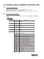
4 CONTROL WITH A DMX512 CONTROLLER
4.1 BASIC ADDRESSING
● Connect all of the units in series using standard DMX512 signal cable.
● Set the DMX512 address in the DIP switch PCB.
● It is possible to have the same DMX address or independent addresses for each fixture.
Note: This product has three DMX512 channel configurations: 【STAGE1】 , 【ARC1】and
【ARC2】.
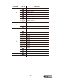
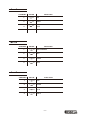
4.2 CHANNEL ASSIGNMENT
STAGE1
BLUE
1
2
CHANNEL FUNCTIONVALUE
3
GREEN
RED
0 255
0 255
0 255
WHITE
0 255
0 10
NO FUNCTION
COLOR MACRO
DIMMER
0 255
4
5
6
11 30
31
51
71
91
111
131
151
171
201
206
211
50
70
90
110
130
150
170
200
205
210
215
RED 100% / GREEN UP / BLUE 0%
RED DOWN / GREEN 100% / BLUE 0%
RED 0% / GREEN 100% / BLUE UP
RED 0% / GREEN DOWN / BLUE 100%
RED UP / GREEN 0% / BLUE 100%
RED 100% / GREEN 0% / BLUE DOWN
RED 100% / GREEN UP / BLUE UP
RED DOWN / GREEN DOWN / BLUE 100%
WHITE 1: 3200K
WHITE 2: 3400K
WHITE 3: 4200K
WHITE 4: 4900K
RED 100% / GREEN 100% / BLUE 100%WHITE100%
216 220

·10·
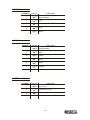
11 255
6
0 40
41 50
51
61
71
81
91
101
221
226
231
236
241
60
70
80
90
100
110
225
230
235
240
245
WHITE 5: 5600K
WHITE 6: 5900K
WHITE 7: 6500K
WHITE 8: 7200K
WHITE 9: 8000K
0 10
7
AUTO6
AUTO7
AUTO8
AUTO9
AUTO1
AUTO2
AUTO3
AUTO4
AUTO5
111 120
121 130
131 255
8
246 250
251 255
WHITE 10: 8500K
WHITE 11: 10000K
AU TO 10
9
0
255
CHANNEL FUNCTIONVALUE
STROBE
NO FUNCTION
FROM SLOW TO FAST
AUTO
NO FUNCTION
AUTO SPEED ADJUSTMENT


1
2
3
4
5
6
7
8
9
10
11
12
13
14
15
16
17
·13·
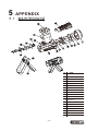
Head cover
Thermal protection device
Power supply
Display PCB
Prive PCB
Abrazine slice
Lens frame2
Lens
Control board
Heat sink
Display glass
Isolator sheet
No
ITEM
5.1 MAINTENANCE
5 APPENDIX
1
2
3
4
6
7
8
10
11
12
13
14
15
16
17
18
19
5
9
18
19
Screw
Lens frame1
LED board
Head casing main section1
Bracket 1
Bracket 2
Head casing main section2
-
 1
1
-
 2
2
-
 3
3
-
 4
4
-
 5
5
-
 6
6
-
 7
7
-
 8
8
-
 9
9
-
 10
10
-
 11
11
-
 12
12
-
 13
13
-
 14
14
-
 15
15
-
 16
16


Briteq MICRO BEAMER RGBW Owner's manual
- Category
- Stroboscopes & disco lights
- Type
- Owner's manual
Ask a question and I''ll find the answer in the document
Finding information in a document is now easier with AI
Related papers
-
Briteq BT-AKKUZOOM set Owner's manual
-
-
-
-
-
-
-
-
-
Other documents
-
Chauvet Professional COLORado Déco Quad-1 Tour User manual
-
-
 afx light ICOLOR210Z Owner's manual
-
ROHS 4X10W RGBW 4 IN 1 User manual
-
SHOWTEC 42720 User manual
-
Expolite TourLED 42 CM IP33 P-Con User manual
-
-
Robe LiteWare HO 2 User manual
-
-
Anolis ArcPar™ 100 User manual
