Cateye EC-C400 User manual
- Type
- User manual

Cateye Ergometer
Instruction Manual
MODEL EC-C400
EC-C4OO
UPRIGHT BIKE
E
C
-
1
2
0
0
O
N
O
F
F

2
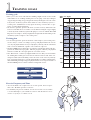
HOW TO USE THIS MANUAL
After first reading the "Start Guide," assemble the machine and give the Model EC-C400
Ergometor type Cat eye Fitness a try.
Once you've become accustomed to the machine, read the "Operation Guide" and experi-
ment with the EC-C400's wealth of functions.
Make use of the "Reference Guide" as needed.
E
C
-
1
2
0
0
CONTENTS
Start Guide Operation Guide Reference Guide
1 Starting with assembly ..................... 7
2 How to adjust each part ................. 10
3 Adapting the pulse sensor ............. 12
4 Trying out the EC-C400 for the
first time .......................................... 13
5 The 6 kinds of programs ................ 16
6 Using the EC-C400 without
a data card....................................... 18
1 Training goals ................................. 24
2 Your strength level and training
index ................................................ 26
3 Fitness test ...................................... 28
4 Fitness test (2)................................. 30
5 HR control training........................ 32
6 Constant wattage control training. 34
7 Hill training..................................... 36
8 Interval training.............................. 38
9 Quick start ...................................... 40
10 How to make a data card............... 42
1 Chest-belt heart rate sensor........... 46
2 Other useful functions.................... 48
3 Troubleshooting ............................. 49
4 Daily maintenance/repair service
warranty/additional pars ................ 50
5 Product specifications .................... 51
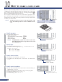
Check that you have all the parts.
I
N
T
E
R
V
A
L
H
I
L
L
C
O
N
S
T
A
N
T
W
A
T
T
A
G
E
H
R
C
O
N
T
R
O
L
F
I
T
N
E
S
S
T
E
S
T
Q
U
I
C
K
S
T
O
P
M
O
D
E
S
T
A
R
T
A
D
V
A
N
C
E
A
E
R
O
B
I
C
A
E
R
O
B
I
C
W
E
I
G
H
T
L
O
S
S
H
R
C
O
N
T
R
O
L
T
O
O
P
E
R
A
T
E
M
A
N
U
A
L
L
Y
P
R
E
S
S
"
Q
U
I
C
K
"
1
2
3
H
I
L
L
1
2
3
I
N
T
E
R
V
A
L
Pedals (L,R)
¤
C
a
t
e
y
e
E
r
g
o
m
e
t
e
r
I
n
s
t
r
u
c
t
i
o
n
M
a
n
u
a
l
M
O
D
E
L
E
C
-
C
4
0
0
EC-C400
UPRIGHT BIKE
E
C
-
1
2
0
0
O
N
O
F
F
D
A
T
A
C
A
R
D
Sensor clip Tools
Saddle
AC adapter
Pulse sensor Data card (10)
Start card (1)
Operating Instructions
Warranty card
Main body
Control unit Legs (2 pcs)
Handlebar & Handlebar post

3
Always unplug from the electrical outlet immedi-
ately after using and before cleaning. Do not
leave plugged in.
Turn all controls to the off position before
removing the plug from the outlet. Remove the
plug without pulling the cord.
Do not operate where aerosol (spray) products
are being used or where oxygen is being adminis-
tered.
Keep the cord away from heated surfaces.
Do not use the unit if the cord or plug is dam-
aged, when the unit does not operate normally,
when it has been dropped or damaged, or when it
is wet. If such events have occurred, contact our
authorized dealer in your location.
INTRODUCTION
Thank you very much for your purchase of the Model EC-C400 Cateye Ergometer. The model EC-C400 is a new high-
tech exerciser with a built-in computerized training system designed specifically to promote cardiovascular fitness and
overall endurance, the keystone of good health. With its endurance test program and four training programs, the EC-
C400 will help you to maintain or improve your physical strength in a fun and pleasant way. We hope you will make good
use of your Cateye Ergometer for years to come.
Before using your new exerciser, please read this manual carefully. Then store it in a safe place along with the warranty card.
Symbol marks used for safety precautions in this manual
The descriptions accompanying the following symbol marks in this manual refer to very important matters in terms of
your safety and handling of the unit.
You are strongly urged to observe these precautions.
Warning
Failure to observe this warning could result in serious injury or death.
Caution
Failure to observe this warning could result in physical injury or damage to the EC-C400.
Important Operations which require caution, items which should be observed in particular as well as certain
additional information are presented in this manual.
Reference This symbol mark denotes helpful information or associated items.
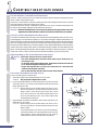
FOR SAFE OPERATION
For safe use, always observe the following rules.
WARNING
• Before using the EC-C400, it is important to consult a medical specialist if you are suffering from any of the following: heart
disease (angina pectoris, myocardial infarction), hypertension, diabetes, respiratory disease (asthma, chronic bronchitis,
pulmonary emphysema, etc.), articular metamorphosis, rheumatism, gout, or other diseases and physical complaints. Preg-
nant women should also consult their doctor before commencing a training program.
• If you are not used to regular physical activity, it may be dangerous to suddenly engage in strenuous activity. Increase your
exercise level gradually.
• If you feel sick or sense something is wrong with your body during exercise, stop immediately.
• Close supervision is necessary when this exerciser is used by, or near children, persons in poor health, or disabled persons.
CAUTION
Never operate the exerciser with the air vents
blocked. Keep the air vents free of lint, hair, and
the like.
Never drop or insert any object into an opening.
Avoid using the unit in manners other than those de-
scribed in this manual. When repairing the unit, be
sure to use genuine parts for Cateye
EC-C400
only.
Avoid using or storing the unit outdoors or in ar-
eas where it is exposed to direct sunlight.
Do not use the unit in areas where temperature
or humidity are high.
Do not touch the main unit or plug if your hands
are wet.
Close supervision is necessary when this exerciser
is used by, or near children, persons in poor
health, or disabled persons.
This equipment has been certified to comply with the limits for a Class B computing device, pursuant to Subpart J of Part
15 of FCC Rules. Only peripherals (computer input/output devices, terminals, printers, etc.) certified to comply with the
Class B limits may be attached to this computer. Operation with non-certified peripherals is likely to result in interfer-
ence to radio and TV reception.

4
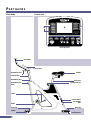
PART NAMES
Main body Control unit
INTERVAL
HILL
CONSTANT
WATTAGE
HR
CONTROL
FITNESS
TEST
QUICK
STOP
MODE
START
ADVANCE
AEROBIC
AEROBIC
WEIGHT LOSS
HR CONTROL
TO OPERATE
MANUALLY PRESS
"QUICK"
1
2
3
1
2
3
INTERVAL
HILL
4
1
2
3
5
6
7
8
9
EC-1200
Handlebar
Handlebar lever
Cable holder
Handlebar post
Handlebar post
knob
Control unit
Saddle
Seat post
Spring lock pin
Crank
Pedal
Caster
Front leg
Leveling knob
Rear leg
Power switch
AC adapter
inlet

5
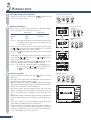
1 Liquid crystal display (LCD)
2 Pattern display
When Hill training or Interval training have been
selected, the pattern (hill shape or training interval) which
is set is indicated by a lamp.
3 Target pulse
Lights and displays the target pulse when the HR control
training has been selected.
4 Training select buttons
FITNESS TEST .. Fitness test is selected.
HR CONTROL ... HR control training is selected.
CONSTANT
WATTAGE ........ Constant wattage control training is se-
lected.
HILL .................... Hill training is selected.
INTERVAL ........ Interval training is selected.
QUICK ................ Quick start training is selected.
5 STOP button
Skips the cool-down phase, or ends the program.
6 Number -/+ buttons
When entering data:
Used to increase or decrease the numeric value or to se-
lect an item.
During exercise:
Used to increase or decrease the pedal torque (resistance)
or wattage.
When the training program finishes:
Used to scroll an exercise graph to assess the training his-
tory.
7 MODE button
When entering data:
Used to go to the next item in the condition settings.
Pressing this button when the check display is in view re-
verts to the initial display.
During exercise, or when an exercise program finishes:
Used to switch the numeric value display at the right-
hand side of the display.
8 START button
Sends the program to the next stage.
9 Card slot (Safety key slot)
Insert a data card.
Insert the safety key when the safety key function is acti-
vated.
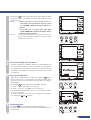
LCD
1 Pulse Scale (pulse/minute)
2 Load Scale (Pedal Resistance) (kg·m)
3 Upper Pulse Limit
The upper pulse limit determined by your age is
displayed.
4 Pulse Graph
5 Load Graph (Pedal Resistance)
6 Exercise Time
Pressing the MODE
MODE
button switches to the loading
level (pedal resistance) display.
7 Pulse (bpm: pulse/minute)
Pressing the MODE
MODE
button switches to the wattage
display.
8 Pedal Cadence (rpm)
Pressing the MODE
MODE
button switches to the
consumed calories display.
9 Time Scale (minute)
0 Button navigation
Pressing a particular button brings up the
corresponding information.

START GUIDE
1 Starting with assembly .............................................................7
2 How to adjust each part ..........................................................10
3 Adapting the pulse sensor .....................................................12
4 Trying out the EC-C400 for the first time ...........................13
5 The 6 kinds of programs ........................................................16
6 Using the EC-C400 without a data card ..............................18
STARTING UP

7
1
Follow the steps starting from the next page and assemble the unit as shown in the figure below.
STARTING WITH ASSEMBLY

8
1
2
4
3
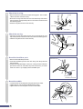
Attach the front leg.
• Remove the two screws from the respective leg pipes. The one with
casters should be used as front leg.
• Place the front leg under the front end of the main body with casters
facing forward, and adjust the position so that the screw holes meet
the fastening points.
• Fasten the leg with the two screws securely.
Attach the rear leg.
• Place the rear leg pipe under the rear end of the main body, and
adjust the position so that the screw holes meet the fastening points.
• Fasten the leg with the two screws securely.
Mount the handlebar post.
• Remove the handlebar post knob.
• Insert the handlebar post into the main body, with the post holes
facing forward.
• Adjust the handlebar height so that one of the post holes meets the
post knob screw hole, and fasten the post knob securely. It will be
easier to screw in if you slightly lift the handlebar post.
Mount the saddle.
• Loosen the bolt of the seat pillar using the wrench provided.
• Tighten the two rods under the saddle with the clamp.
• Tighten the bolt of the seat pillar and secure the saddle.
O
N
O
F
F
Caster
Front
Screw
Front leg
Screw
Rear
Tighten
Loosen
Handlebar post
Handlebar post knob
Seat pillar
Wrench

9
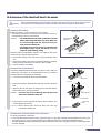
5
6
Attach the pedals.
• Use the No.15 end of the spanner to attach the pedals firmly to the
cranks.
• The right and left pedals are different, so be sure to check for R and
L marks.
• Tighten the right pedal by turning clockwise, and the left pedal by
turning counterclockwise.
Caution: If the pedals are not attached firmly enough to the
crank, they can cause an irritating noise.
Be sure to attach them firmly.
Install the control unit.
Reference: Units of weight, and units of pedaling resistance can
be changed using the select switches at the back of the
control unit. The settings before shipping are as fol-
lows; units of weight: lbs, and units of pedaling resis-
tance unit: kg·m.
For information on the various settings which can be
carried out with these switches, refer to the Reference
section on page 48.
• Insert the cable connector into the cable inlet on the back of the
control unit, and cover up the connector with the connector cover.
Caution: Insert the cable connector fully. If the connector is not
pushed fully home, a connection failure may occur.
• Using the four screws provided, mount the control unit on the
handlebar post.
• Insert the cable holder tip into the upper smaller hole on the handle-
bar post, to hold the cable in place.
Crank
No.15 end of the
spanner
Left Right
Front
Cable inlet
Cable connector
connector cover
Screw
Handlebar post
Smaller hole
Cable holder

10
1
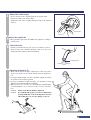
Adjust the saddle height.
• Pulling on the spring lock pin will enable you to move the seat post
up or down. When the saddle is at the correct level for you, release
the knob and move the seat post slightly.
• A spring inside the spring lock pin will drive a pin into the nearest
hole in the seat post, locking it in that position.
• The pitch of the seat post holes is 1" (approx. 25mm).
Caution: Do not attempt to adjust the saddle height while you
are mounted.
Adjust the handlebar height.
• Decide the approximate height by one of the 3 holes on the handle-
bar post, then fix the final position by adjusting the handlebar angle.
• Remove the handlebar post knob.
• Hold the handlebar post where one of the post holes meets the post
knob screw hole, and fasten the post knob securely. It will be easier
to screw in if you slightly lift the handlebar post.
• The pitch of the handlebar post hole is 3" (approx. 76mm).
Caution: Make sure to grasp the handlebar post firmly when
you loosen the handlebar post knob, otherwise it
could drop suddenly and damage the unit.
Adjust the handlebar angle.
• When you turn the handlebar lever clockwise (when mounted), the
handlebar is loosened. The lever turns idle when pulled downward.
• Rotate the handlebar and hold it at the desired angle.
• Turn the handlebar lever counterclockwise to fix the handlebar
angle.
Caution: Loosen the handle and then carry out angle adjustment.
If the handle is turned when the lever has not been loos-
ened fully, the handle may become loose.
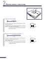
2
HOW TO ADJUST EACH PART
2
3
Seat post
pitch 1”
(approx. 25mm)
Pull
Spring lock pin
Tighten
Loosen
Handlebar post
Handlebar post
knob
Handlebar
Tighten
Loosen
Idle
Handlebar lever
E
C
-
1
2
0
0
O
N
O
F
F
I
N
T
E
R
V
A
L
H
I
L
L
C
O
N
S
T
A
N
T
W
A
T
T
A
G
E
H
R
C
O
N
T
R
O
L
F
I
T
N
E
S
S
T
E
S
T
Q
U
I
C
K
S
T
O
P
M
O
D
E
S
T
A
R
T
A
D
V
A
N
C
E
A
E
R
O
B
I
C
A
E
R
O
B
I
C
W
E
I
G
H
T
L
O
S
S
H
R
C
O
N
T
R
O
L
T
O
O
P
E
R
A
T
E
M
A
N
U
A
L
L
Y
P
R
E
S
S
"
Q
U
I
C
K
"
1
2
3
H
I
L
L
1
2
3
I
N
T
E
R
V
A
L
1
2
3
4
5
6

11
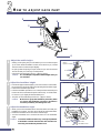
Adjust the saddle angle.
• Loosen the bolt of the seat pillar using the wrench provided.
• Adjust the saddle to the desired angle.
• Tighten the bolt of the seat pillar, fixing the angle of the saddle as
desired.
Adjust the pedal belt.
• The pedal belt length of the EC-C400 can be adjusted according to
your shoes size.
The level knobs
• Ideally, you should only use your exerciser on a hard, level floor.
• If the exerciser tilts or wobbles during use, turn one or more level-
ling knobs until a stable position is maintained.
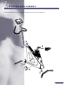
Adjusting all parts to fit
•Make various height and angle adjustments so that your posture
when seated on the exerciser is like that shown in the diagram be-
low.
• For proper saddle height, your knees should be slightly bent when
the pedal is at its lowermost position.
• For proper handlebar height and angle, you should be leaning
slightly forward when holding the handlebar.
•When you move the exerciser, face the handlebars, pull handlebar
forward, lifting the rear or exerciser, roll the exerciser on its direc-
tion.
Caution: Firstly, check that the handle is tightened.
Caution: Do not lift the bike by the seat to move it. Tilt the bike
by using handlebars as shown in diagram to more the
bike. Lifting the seat can cause damage to the seat.
4
6
7
5
Seat pillar
Wrench
Lower
Higher
Leveling knobs
EC-1200

12
3
ADAPTING THE PULSE SENSOR
This model detects and displays your pulse rate during exercise by the earlobe sensor from your earlobe. Being a sensitive elec-
tronic part, the earlobe sensor must be handled with sufficient care.
Important: When the chest-belt sensor is used, remove the earlobe sensor plug from the control unit. Signals from the chest-
belt sensor cannot be received if the earlobe sensor is connected.
Connect the pulse sensor.
• Insert the pulse sensor plug into the sensor jack on the back of con-
trol unit.
Handling of sensor cable.
• Attach the sensor clip on the handlebar with the sensor cable in be-
tween, and adjust the length of the sensor cable.
• When not in use, keep the earlobe sensor attached on the clip.
Use pulse (earlobe) sensor during exercise.
• Clip the earlobe sensor at the center of your right or left earlobe.
• When it is cold, massage your earlobe before use to improve blood
circulation.
• Attach the cable clip to your clothes to prevent excessive swinging of
the sensor cable.
• Ear rings or other ornaments must be removed before attaching the
sensor and during exercise.
• Try not to change the position of the earlobe sensor during the exer-
cise.
• When removing the earlobe sensor after exercise, be sure to remove
also the cable clip.
IN
T
E
R
V
A
L
H
I
L
L
CO
NSTAN
T
W
AT
TAG
E
H
R
C
O
N
T
R
O
L
F
I
T
N
E
S
S
T
E
S
T
Q
U
I
C
K
S
T
O
P
M
O
D
E
S
T
A
R
T
1
2
3
1
2
3
Pulse sensor jack
Pulse sensor plug
Handlebar
Pulse (earlobe) sensor
Cable clip
Pulse (earlobe)
sensor
Cable clip
Pulse (earlobe)
sensor
Sensor clip

13
1
3
2
4
TRYING OUT THE EC-C400 FOR THE FIRST TIME
1
2
3
Turn on power and attach earlobe sensor
• Insert the AC adaptor into the AC adapter inlet at the rear of the
exerciser.
• Insert the plug of the AC adaptor into any household AC outlet
(120V).
Because of the danger of electric shock, do not
insert the AC plug into an outlet if your hands are
wet.
Caution: • Do not use any AC adaptor other than the one sup
supplied with the Model EC-C400.
• Connect the power plug directly to a power socket,
for example one on the wall. If two or more ma
chines are connected using an extension cord, etc, a
power voltage failure may occur and the machine
may not operate properly.
• Turn on the power switch.
• The initial display appears and prompts you to insert the card or to
select a training mode.
• Attach the earlobe sensor to your earlobe. When it is cold,rub your
earlobe to facilitate blood circulation before attaching the earlobe
sensor.
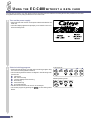
Insert the start card (the red card provided).
• Find the red card (start card) in the packaging of the exerciser. Insert
this card into the slot of the control unit (card slot).
If the card is inserted in the wrong direction, a card read
error occurs and operation does not start. Make sure to insert the
card in the direction shown in the diagram.
Caution: Use only the red card at this stage. It is a sample card
with exercise data already stored in it. The unit will
not work with the black cards since they do not con-
tain any data yet.
• For information on how to make a data card, refer to page 42.
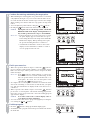
Check the screen display.
• The display on which the training conditions can be checked ap-
pears, as described below. The function of each button is shown at
the bottom of the display.
Important: If this display does not appear or if a card error ap-
pears in the display, pull the card out and insert it
again slowly.
Reference: Settings which have already been specified can be
changed on the display. For now, however, the goal is
get you acquainted with Model EC-C400. Please pro-
ceed, therefore, to the following instructions. For in-
formation on how to change various settings, refer to
“Using the EC-C400 without a data card” on page 18.
• The numeric values in the display represent various training condi-
tion settings.
1 “Hill” shows the type of training program and is short for “Hill
training” where the pedal load (i.e. resistance) changes automati-
cally to simulate the effect of cycling in mountainous terrain.
2 “Pattern 1” indicates the shape of the mountain to be climbed. “1”
is the gentlest slope.
3 “Age 50” is your age. For now, leave this setting as it is.
4 “Exercise Time 16:00” is the exercise time of this training session.
For now, leave this setting as it is.
O
N
O
F
F
4
Power switch
AC adapter inlet
Plug
I
N
T
E
R
V
A
L
H
I
L
L
C
O
N
S
T
A
N
T
W
A
T
T
A
G
E
H
R
C
O
N
T
R
O
L
F
I
T
N
E
S
S
T
E
S
T
Q
U
I
C
K
STOP
M
O
D
E
S
T
A
R
T
A
D
V
A
N
C
E
A
E
R
O
B
I
C
A
E
R
O
B
I
C
W
E
I
G
H
T
L
O
S
S
H
R
C
O
N
T
R
O
L
T
O
O
P
E
R
A
T
E
M
A
N
U
A
L
L
Y
P
R
E
S
S
"
Q
U
I
C
K
"
1
2
3
H
I
L
L
1
2
3
I
N
T
E
R
V
A
L
Start card
Card slot
Warning

14
1
2
4
5
4
Starting exercise
3
Press the START button to start
• Press the
START
button.
• A buzzer sounds and the hill training display appears.
• “START” as well as a mountain-like shape appear in the display,
signifying that the hill training session has started.
Start pedaling slowly.
INTERVAL
HILL
CONSTANT
WATTAGE
QUICK
MODE
START
• This display shows various conditions as they apply to you during
training.
1 Elapsed time since start of training session
2 Pulse rate, per a minute
3 Revolutions, per minute, of the pedal cranks
4 Changes in pulse rate and pedal resistance are shown on the graph. As time elapses, the blinking point in the
graph moves. When 10 minutes elapses, 5-minutes’ worth of graphical data scrolls to the left. This accumulated
data can be analyzed, via scrolling, after the training session has been completed.
5 Pressing the
MODE
button toggles between displays A and B. (A: exercise time, heart rate, pedal cadence,
B: pedal loading level, wattage, consumed calories)
4
LCD

15
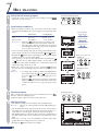
5
Changing the display
6
Finishing training
So far we have covered only the beginning of the Model EC-C400 Cateye Ergometer functions. Let us move on to an explanation
of other functions.
INTERVAL
HILL
CONSTANT
WATTAGE
QUICK
MODE
START
HILL
CONSTANT
WATTAGE
HR
CONTROL
FITNESS
TEST
STOP
Bring up the calories display by pressing
MODE
button
• Pressing the
MODE
button changes from the display with the exercise
time, heart rate, and pedal cadence to that with the pedal loading
level, wattage, and consumed calories. Pressing the MODE button
again reverts to the first display.
• You are now on the exerciser for your first ride. As you train, the
pedal resistance will change and accordingly your pulse rate will
change. The EC-C400 Ergometer thus allows you to monitor all
such information while you train.
Finish your training
• After 16 minutes, a buzzer sounds, and the screen enters the cool-
down phase.
Reference: If you do not wish to complete the full 16-minute
training session, you may stop the session at any time
by pressing the
STOP
button. The cool-down phase
starts when the
STOP
button is pressed.
• The cool-down phase lasts for five minutes. This can be skipped by
pressing the
STOP
button at any time during the cool-down phase.
• When the 5-minute cool-down phase elapses or when the
STOP
button is pressed during that time, the training session finishes.
The LCD does not go off even though the training session is now
over. With regard to the graphic display of information related to
the training session after 10 minutes, the information can be
“scrolled” and viewed using the
and buttons.
• Pressing the
STOP
button again ends the program and the initial dis-
play then reappears.

16
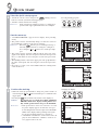
Hill training ( training by cycling up mountains )
• Pedal resistance changes over time to simulate the effect of cycling in the mountains.
All changes in pedal resistance are shown on the screen.
• The following three types of mountain profiles plus one customized pattern are pro-
grammed.
Pattern-1: the Rockies (U.S.A.)
Pattern-2: the Cascades (U.S.A.)
Pattern-3: the Pyrenees (France, Spain)
• The mountain profiles from 1 to 3 are arranged in order of ascending difficulty. Do
not strain yourself, but rather enjoy the form of each mountain.
• The cycle time for a given pattern is 15 minutes. The same pattern is repeated in
accordance with the exercise time.
5
THE 6 KINDS OF PROGRAMS
Fitness Test (physical fitness test)
• Over a period of 10 minutes, you will encounter three different levels of pedal resis-
tance. Your pulse will change in response to the different levels of resistance, and this
change in pulse will be used to calculate your overall fitness level, also expressed is
MOU (VO2 max). MOU stands for maximum oxygen uptake. The higher your over-
all fitness level, the greater your endurance.
• Your MOU value is compared with the MOU values of other people who are the
same age and sex as you. You are given a physical strength number from 1 to 5
depending on how you rank.
• These results should give you a good idea of your own fitness level and help you to
determine what sort of training program will be the most effective for you. For infor-
mation on how to choose a training program, refer to “Your strength level and train-
ing index” on page 26~27 in the Operation section on this booklet.
HR control training (training at a constant pulse rate)
• You set the pulse rate at which you want to exercise and the Ergometer automati-
cally adjusts pedal resistance to maintain that pulse rate. This is an ideal basic form of
aerobic training.
• As you repeat the exercise at a certain pulse rate and make progress in your fitness
level, you will be able to create a greater work intensity under the same pulse rate.
Further, you will be able to try exercising at a higher target pulse rate.
Constant Wattage Control Training (training at a constant energy
expenditure)
• The wattage (work intensity) shown on the screen of the Ergometer is calculated
from pedal resistance (kg·m) and cadence (rpm).
• In constant wattage control training, you set the desired work intensity in wattage.
The Ergometer automatically adjusts the pedal resistance (kg·m) depending on your
pedal cadence (rpm), so as to keep a constant wattage (work intensity).
• This type of training is also called constant load, and is often used in cardio-vascular
rehabilitation.
Control range:
cadence: 40~100 rpm
wattage: 25~200 watts
Caution: If you set your target wattage as under 50 watts, control limit of ca-
dence (rpm) becomes under 100 rpm.
TORQUE
PULSE RATE
WATTAGE

17
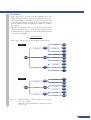
Interval training (exercise + relief periods)
• By switching back and forth between exercise and relief periods of varying length,
interval training gives you the kind of program that professionals use to build their
stamina and energy.
• On the Model EC-C400, 3 patterns of interval training programs are preset for devel-
oping dashing power, speed, or your stamina respectively.
Pattern-1: dash strength training (sprint power)
15 seconds exercise followed by a 45 sec-
ond relief.
Pattern-2: speed training (anaerobic power)
30 seconds of exercise followed by a 60 sec-
ond re lief.
Pattern-3: stamina training (aerobic power)
60 seconds of exercise followed by a 30 sec-
ond relief.
• Choose one of the above patterns, and adjust the level of intensity by specifying pedal
resistance (torque:kg·m)
• During the exercise period (increased load portion of interval), you should pedal with
your greatest effort, then you should pedal slower and lighter during relief period
(lower load portion of interval).
• In the TLD-3 stamina training program, it is advisable to pedal fast enough in the
exercise period to keep your pulse rate at 60~80% of the maximum pulse rate for
your age. (Refer to page 24~25)
Quick start (training at any desired pedal resistance)
• You choose the pedal resistance (torque: kg·m), and it stays constant regardless of
your pulse rate or pedal cadence. This is the most traditional way in which stationary
bicycles have been used.
Torque setting range: 0.5~4.0 kg·m
Minimum graduation: 0.1 kg·m
When the upper pulse limit alarm occurs
Caution: If your heart rate reaches the upper limit, an alarm sounds and
“STOP EXERCISE” blinks in the display. Accordingly, the pedal
resistance reaches the minimum and the program terminates forcibly.
Checking the progress of the training session
After training, you can check the progress of the training session just completed. If
the exercise time is longer than 10 minutes, all graphical information can be dis-
played by scrolling the data using the
and buttons.
button: Used to scroll the display rightward for 5-minutes’ worth of data.
button: Used to scroll the display leftward for 5-minutes’ worth of data.
Pressing the
STOP
button to end the program deletes data for the training session
from the memory of the exerciser.
TORQUE

18
3
2
INTERVAL
HILL
CONSTANT
WATTAGE
HR
CONTROL
FITNESS
TEST
QUICK
STOP
MODE
START
Select a training program.
• Attach the earlobe sensor, and then select a training program using
one of the six training selection buttons.
• The six training selection buttons are aligned in the following order
from the left:
1 Fitness test
2 HR control training
3 Constant wattage control training
4 Hill training
5 Interval training
6 Quick start training
• This time we will choose “HR control” as an example.
• Choose the program by pressing the
HR
CONTROL
on the training select
button.
1
Training mode
6
USING THE EC-C400 WITHOUT A DATA CARD
The red card you used for your first session serves to input the type and conditions of training. But it is also possible to do the same
thing without the card, by using the buttons on the control unit.
4
1
HILL
CONSTANT
WATTAGE
HR
CONTROL
FITNESS
TEST
STOP
Turn on the power supply.
• Plug in the exerciser and turn on the power switch at the back of the
main unit.
• The initial display appears and prompts you to insert the card or to
select a training mode.
2
Selecting training mode
5
6

19
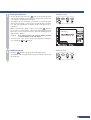
3
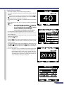
Input training conditions.
• The screen prompts you to set the training conditions.
• The screen changes as shown here, and the initial value for age (40)
is shown.
• Your age can be increased or decreased as desired using the
and
buttons. The value changes rapidly if one or other button is
pressed and held for longer than one second.
• For example, press the
button to change the value for age from 40
to 52.
• After inputting your age, go on to the next screen by pressing the
MODE
button.
Caution: • Do not press the
START
button before completely in-
putting the data. If you press the
START
button be-
fore completing data input except the age, the skip
function is activated, and exercise begins.
• Input contents vary depending on the program.
• Try changing the displayed target pulse rate from 117 to 109.
• In accordance with the target pulse rate, the arrow moves from aero-
bics to weight loss.
• After finish inputting your target pulse rate, go to the next screen by
pressing the
MODE
button.
• Input the exercise time.
• Press the
MODE
button to bring up the display in which the various
training conditions can be checked. Check that the training condi-
tions are correct.
• To change the settings, display and highlight the desired item using
the
and buttons and then press the
MODE
button. The input dis-
play for the selected item appears, allowing the particular settings to
be changed, as desired.
Reference: The card is a tool to instantly set a program and training
conditions. Usually you have to set such conditions by
pressing buttons before each session, but the data card
saves you the trouble. The age, upper pulse limit setting,
and target pulse rate will be automatically entered. See
“How to make a data card” on page 42.

20
Starting exercising
Start your exercise.
• When you have finished setting training conditions, press the
START
button and start exercise. The message “Start warming-up” is dis-
played to announce that the HR control training program has
started. Start pedaling slowly.
Reference: To skip the warm-up period and start a HR control
training session immediately, press the
START
button.
• The pedal resistance can be changed arbitrarily during or after
warm-up. To change the pedal resistance, press the
or button.
• Within a few moments, the pedal resistance (torque) is automati-
cally adjusted ±0.1 kg·m every 15 or 30 seconds so that the difference
between the measurement value and the target value becomes
within ±3 bpm.
Finish your exercise.
• A buzzer will sound when the exercise time previously set has
elapsed.
Reference: You can stop training at any time, even before the
buzzer sounds.
• The pedal resistance (torque) drops to the minimum of 0.5 kg·m,
and the 5-minutes cool-down phase then starts.
• To complete the cool-down phase, remain in cool-down mode. Mea-
surement still continues during the cool-down phase and the exer-
cise time switches to the remaining cool-down time.
• If the 5-minute cool-down time is not necessary, press the
STOP
but-
ton to skip this phase.
4
5
INTERVAL
HILL
CONSTANT
WATTAGE
QUICK
MODE
START
Changing the display
INTERVAL
HILL
CONSTANT
WATTAGE
QUICK
MODE
START
• Pressing the
MODE
button during exercise toggles between the display
with the exercise time, heart rate, and pedal cadence and that with
the pedal loading level, wattage, and consumed calories. The pulse
change is shown in the upper part of the graph and the pedal resis-
tance change is shown in the lower part of the graph.
Reference: After 10 minutes of the session have elapsed, 5-min-
utes’ worth of session data scrolls off the display, to
the left.
Page is loading ...
Page is loading ...
Page is loading ...
Page is loading ...
Page is loading ...
Page is loading ...
Page is loading ...
Page is loading ...
Page is loading ...
Page is loading ...
Page is loading ...
Page is loading ...
Page is loading ...
Page is loading ...
Page is loading ...
Page is loading ...
Page is loading ...
Page is loading ...
Page is loading ...
Page is loading ...
Page is loading ...
Page is loading ...
Page is loading ...
Page is loading ...
Page is loading ...
Page is loading ...
Page is loading ...
Page is loading ...
Page is loading ...
Page is loading ...
Page is loading ...
Page is loading ...
-
 1
1
-
 2
2
-
 3
3
-
 4
4
-
 5
5
-
 6
6
-
 7
7
-
 8
8
-
 9
9
-
 10
10
-
 11
11
-
 12
12
-
 13
13
-
 14
14
-
 15
15
-
 16
16
-
 17
17
-
 18
18
-
 19
19
-
 20
20
-
 21
21
-
 22
22
-
 23
23
-
 24
24
-
 25
25
-
 26
26
-
 27
27
-
 28
28
-
 29
29
-
 30
30
-
 31
31
-
 32
32
-
 33
33
-
 34
34
-
 35
35
-
 36
36
-
 37
37
-
 38
38
-
 39
39
-
 40
40
-
 41
41
-
 42
42
-
 43
43
-
 44
44
-
 45
45
-
 46
46
-
 47
47
-
 48
48
-
 49
49
-
 50
50
-
 51
51
-
 52
52


Cateye EC-C400 User manual
- Type
- User manual
Ask a question and I''ll find the answer in the document
Finding information in a document is now easier with AI
Related papers
Other documents
-
Proteus ISS 500 Owner's manual
-
Tunturi E-80R Recumbent Bike User manual
-
 ultega ERGOMETER RACER 600 User manual
-
Tunturi E 860 User manual
-
Kettler 7861-859.A Computer Manual
-
Maxxus Speedbike S1 User manual
-
Vermeiren Nathalie User manual
-
Snap-On TECHANGLE User manual
-
Snap-On ControlTech Micro User Instructions
-
 Land Fitness CT-300 User manual

