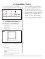
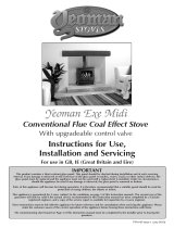
Stovax F40 is a conventional flue coal effect stove with a fully automatic battery operated gas control which can be lit using the hand set or touch pad. Flame height can be adjusted and the stove also features an LED display that provides information such as temperature, clock and battery status. The F40 Avanti is suitable for use in GB and IE using Natural Gas at a supply pressure of 20mbar or LPG at a supply pressure of 28mbar (Butane) or 37mbar (propane).
Stovax F40 is a conventional flue coal effect stove with a fully automatic battery operated gas control which can be lit using the hand set or touch pad. Flame height can be adjusted and the stove also features an LED display that provides information such as temperature, clock and battery status. The F40 Avanti is suitable for use in GB and IE using Natural Gas at a supply pressure of 20mbar or LPG at a supply pressure of 28mbar (Butane) or 37mbar (propane).


-
 1
1
-
 2
2
-
 3
3
-
 4
4
-
 5
5
-
 6
6
-
 7
7
-
 8
8
-
 9
9
-
 10
10
-
 11
11
-
 12
12
-
 13
13
-
 14
14
-
 15
15
-
 16
16
-
 17
17
-
 18
18
-
 19
19
-
 20
20
-
 21
21
-
 22
22
-
 23
23
-
 24
24


Stovax F40 is a conventional flue coal effect stove with a fully automatic battery operated gas control which can be lit using the hand set or touch pad. Flame height can be adjusted and the stove also features an LED display that provides information such as temperature, clock and battery status. The F40 Avanti is suitable for use in GB and IE using Natural Gas at a supply pressure of 20mbar or LPG at a supply pressure of 28mbar (Butane) or 37mbar (propane).
Ask a question and I''ll find the answer in the document
Finding information in a document is now easier with AI
Related papers
-
Stovax 5 User manual
-
-
-
-
-
-
-
-
-
Other documents
-
 Yeoman PR1145 User manual
-
Roberts Revival 250 (R250)( Rev.1) User guide
-
Focal Point Flueless Gas Stove User manual
-
 Broseley Winchester Gas Stove Installation guide
-
Numatic TTB1840G Owner Instructions
-
-
 crystal fires Chicago Installation & Servicing Book
-
AGA Classic Range Gas Owner's manual
-
-
 Broseley Evolution 5 Gas Stove Installation guide


