Hayes Microcomputer Products ASLH306 User manual
- Category
- Networking
- Type
- User manual
This manual is also suitable for

ASL Holdings Limited 19/09/2005 1
Draft Copy Version 2c
Delta Plus MOBILE II
GSM/GPRS Class 10 with TCP/IP stack modem
Part No: ASLH306
User Guide
DRAFT COPY

ASL Holdings Limited 19/09/2005 2
Draft Copy Version 2c
Delta Plus MOBILE II GSM/GPRS Class 10 with
TCP/IP stack modem

ASL Holdings Limited 19/09/2005 3
Draft Copy Version 2c
Contents
Guide to the manual
Disclaimer
Copyright Notice
Trademarks
Introduction
Features
Connecting to your Terminal or Computer
Supplying power to the modem
Battery Powered version.
Antennae.
Subscriber Identity Module card.
Configuring the modem
AT Command set
Sony Ericsson commands
S Registers
Modem result codes
GPRS operation
Remote access feature
Pay as you go SIM support
LED Status
Technical Specifications
Appendices

ASL Holdings Limited 19/09/2005 4
Draft Copy Version 2c
Delta Plus MOBILE II GSM/GPRS Class 10
With TCP/IP stack modem
Hardware User Guide
Guide to the manual
This manual contains detailed technical information about the Delta Plus
MOBILE II GSM/GPRS modem, including the commands necessary to
configure and use it in your particular application. If you require further
technical detail on this modem, please call our Technical Support Group.
Disclaimer
This manual has been checked for accuracy. The information included in this
document is pertinent to all versions of the Delta Plus MOBILE II GSM/GPRS
modem at the time of publication. Subsequent products and manuals are
subject to change without prior notification. Therefore ASLH Ltd. will take no
responsibility for damages incurred, either directly or indirectly, from errors,
omissions or inaccuracies between the product and the manual.
Copyright Notice
This manual is copyrighted by ASLH Ltd. with all rights reserved. Under
copyright laws, this manual may not be reproduced in any form without prior
written permission of ASLH Ltd. No patent liability is assumed however, with
regard to the use of the information contained herein.
Trademarks
Hayes is a trade mark of Hayes Microcomputer Products Inc.
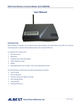
Introduction
Thank you for purchasing this ASLH Ltd modem, which is guaranteed for one
year from the date of purchase. If, after reading this manual, you have any
problems or queries regarding this modem, please contact ASLH Ltd. from
whom the modem was purchased. In the unlikely event of you needing to
return the modem to us, you must first call our Returns Department, to obtain
a Return Authorisation Number (RAN). This number must be clearly marked
on the outer packaging containing the faulty modem, and addressed for the

ASL Holdings Limited 19/09/2005 5
Draft Copy Version 2c
attention of the Returns Department. No goods will be accepted without a
Return Authorisation Number.
Please enclose a copy of your original purchase invoice, to enable us to
determine the warranty status. If no fault is found, a charge will be made to
cover the costs of testing and carriage. Your original or replacement modem
will be returned with an engineering report on the fault found. Thank you for
your co-operation.
The Delta Plus MOBILE II is a new low powered high speed GSM/GPRS
modem which has been specifically designed to meet the requirements of the
telemetry market and specifically applications within the Automatic Meter
Reading (AMR) arena.
The purpose of this manual is to enable the user to set up, configure and use
the modem in a manner suitable for any given application. A basic level of
modems and data communication technology is assumed.
Features
DTE speeds up to 9600 bps
Bearer channel speeds of 9600 bps, 4800 bps, 2400 bps and 1200 bps.
Supports auto-dial and auto-answer on number of rings
NVRAM stores configuration parameters
Suitable for approvals/use in most countries
Interface is a 25 pin D-type RS232 Connector
Power supply input on pins 9 and 15 of 25-way “D” type connector
Auto Shutdown minimises RS-232 Power consumption during periods
of inactivity.
Environment – Temperature : 0-50°C Humidity : 95% non condensing
Enhanced AT command set.
Integrated call progress and dialling.
Advanced power supply handling techniques.
Remote access capability.
Dual Band - ie. E-GSM (900 Mhz) or GSM (1800 Mhz)
GPRS – Mobile Originate and Listen modes. (Class 10)
Internal battery option.
External power option
Connecting to your Terminal or Computer
The 25 way D-type connector on the top of the modem provides the relevant
input and output connections to asynchronous (Serial RS-232 and
compatible) controllers. To establish a connection the modem can be directly
connected to a suitable 25 way socket on your computer or other DTE device,
or a short RS-232 cable can be used. When connecting the modem to the
DTE device, consideration must be given to the power supply arrangements
as most devices will not provide a suitable supply to the modem via the 25
way D-type connector.

ASL Holdings Limited 19/09/2005 6
Draft Copy Version 2c
The 25 way D-type connector is wired as follows:
Pin number, name and mnemonic:
2 Transmit Data TxD
3 Receive Data RxD
4 Request to Send RTS
5 Clear to Send CTS
6 Data Set Ready DSR
7 Signal Ground/Supply Ground SG
8 Data Carrier Detect DCD
9 Power In PI
15 Power In PI
20 Data Terminal Ready DTR
22 Ring Indicator RI
Supplying power to the modem
The Delta Plus MOBILE II GSM/GPRS modem is powered via the RS232
interface connector. Pins 9 and/or 15 require a +7 to +24 Volts DC supply
(issue F. board) Earlier issues of the board require +7 to +15Volts. The
modem consumes 0.3 Watts. (See appendix). The supply to the modem is
floated across internal SuperCaps. These devices hold a considerable charge
and will allow the modem LED’s to continue to function for several minutes
after the removal of the power supply. This enables the modem to be used in
environments where the power supply is either intermittent and/or inadequate
(within reason) for a conventional modem product.
Battery powered version.
The GSM/GPRS modem is also available as a battery powered device. The
battery employed in the modem is a Lithium Ion Polymer type and is subject
to a minimum duty cycle of 1000 operations.
The battery is fitted in addition to the “Super Caps” that are present in
the standard modem and will power the modem for approximately two
minutes after the external supply has been removed. This is regardless of
whether or not the modem is on line. When the modem shuts down it will
issue a “Goodbye” message to the interface.
Additionally the modem can be switched off using an AT command.
The AT+K command will shutdown the entire modem (not just the Sony
Ericsson module as is the case with other ASLH 306 products) within 15
seconds. If the power supply to the modem is not removed within 30 seconds

ASL Holdings Limited 19/09/2005 7
Draft Copy Version 2c
of the modem issuing the “Goodbye” message then it will commence its
power up sequence and restart.
The battery powered modem will power up within 5 seconds after the
external supply is applied given that the battery and capacitors are fully
charged and that the modem is operating at room temperature. If the battery
and capacitors are not fully charged and/or the modem is not operating at
room temperature then the power up sequence will take longer.
Antennae.
The Delta Plus MOBILE II GSM/GPRS modem is designed to work with many
industry standard antennae. Connection to the antenna is via a flying lead
terminated with a SMA type co-axial connector. The selection of the most
suitable antenna in any given installation will be dependent upon factors such
as the distance from the cell site, signal strength, power supply levels, and
other physical constraints. ASLH Ltd. will be pleased to assist customers with
the selection of suitable antennae.
Subscriber Identity Module card.
This product requires a suitable Subscriber Identity Module (SIM) card
inserted in the right hand side of the modem. The SIM card is provided by the
network service provider eg. O2, Vodafone, Orange etc. This card must be
data enabled, ie. a voice only SIM will not work. Additionally, if the product is
to be used for GPRS applications then the SIM card must be GPRS enabled.
This mode will be set as either mobile originate or terminate (IP listen)
depending upon the users requirements.
ASLH Ltd. is able to provide network service supplied by the aforementioned
companies.
Configuring the modem
This is achieved by the use of the standard Hayes(™) AT command set as
utilised in conventional land line modems. A comprehensive list of AT
commands used by the Delta Plus MOBILE II GSM/GPRS modem follows.
AT Command set
AT+ commands should be used alone, not concatenated ie AT+Y<cr>
not AT+YS0=1<cr> etc).
AT A
Answer mode enable

ASL Holdings Limited 19/09/2005 8
Draft Copy Version 2c
Causes the modem to answer an incoming call.
AT D
Dial Command
Causes the modem to go on line and dial the following telephone number
subject to parameters set in the dial string.
eg: ATDT 12345 123456^m
Where “D” = Dial, “T” = Tone (Compatibility only), ^m = Carriage return.
AT E
Local Echo in command mode.
AT E0 = Local Echo off
AT E1 = Local Echo on
AT H
Hang Up command.
This command causes the modem to disconnect from the telephone line.
AT I
Identifier command.
ATI 0 displays: GR47
ATI 1 displays: CXC1122528
ATI 3 displays: GR47 Cable Modem
ATI 5 displays, for example:
Configuration Settings on Channel 0
&C: 1
&D: 0
*E2IPA: 0
*E2IPO: 0
*E2IPS: 2,10,2,1020
*EENMEA: 0
+CGATT: 1
+CGEREP: 0,0

ASL Holdings Limited 19/09/2005 9
Draft Copy Version 2c
+CGREG: 0,1
+CHSR: 0
+CHSU: 0
+CMEE: 0
+CMUX: 0,0,1,31,10,3,30,10,2
+CR: 0
+CRC: 0
+CRLP: 61,61,48,6,0
+CRLP: 120,120,48,6,2,3
+CVHU: 2
+ICF: 3,3
+IFC: 2,2
+ILRR: 0
+IPR: 9600
E: 1
M: 0
Q: 0
S0: 001
S10: 002
S2: 043
S3: 013
S4: 010
S5: 008
S6: 002
S7: 050
S8: 002
V: 1
X: 4
Due to the architecture of the interface circuitry not all of the above
commands will necessarily be displayed each time.
ATI 7 displays: GR47 Profile
Interfaces: System Bus
ATI 9 displays: ($ERI0044\\MODEM\\GR47 Cable Modem0D)
AT O
Return to on line state command
This command returns to modem to the on line data transmission state
following an on line command mode session. ie. it is used to return to data
mode after the +++ escape sequence has been entered.
AT Q

ASL Holdings Limited 19/09/2005 10
Draft Copy Version 2c
Quiet mode. Defines whether or not messages generated by the modem are
sent to the DTE.
AT Q0 = Quiet mode off
AT Q1 = Quiet mode on
AT V
Verbose mode enable. Defines whether the above messages are displayed
as readable text or numeric values.
AT V0 = Verbose mode disabled
AT V1 = Verbose mode enabled
AT X
Result codes. These are the messages generated by the modem when
connection or disconnection is attempted.
There are 5 sets of result codes available (numbered 0 - 4). The ATX
command is used to select which result code set to use. The selection of the
result code set, also affects the way the modem detects dial tone and busy
tones.
ATX0 Selects the Basic code set. In this mode dialling will be carried out
regardless of whether a dial tone is detected or not (this is called Blind
Dialling). If successfully connected, the 'CONNECT' message will be returned
from the modem. No indication is made as to the speed the modem is
connected at.
ATX1 - Selects the extended result code set. Connection is as for X0 except
that the modem now indicates the connection speed in the connect message,
e.g.
"CONNECT 300" when connected at 300bps, "CONNECT 1200" when
connected at 1200bps.
ATX2 - Same as ATX1 with the addition of dial tone detection.
ATX3 - Same as ATX1 with the addition of busy tone detection.
ATX4 - Same as ATX1 with addition of dial tone and busy tone detection.
These commands are for compatibility only.
AT Z
Modem Reset
Resets the modem without changing any parameters

ASL Holdings Limited 19/09/2005 11
Draft Copy Version 2c
AT &C
Carrier control. This parameter defines the operation of pin 8 (DCD) of the
RS 232C interface.
AT &C0 = Always on
AT &C1 = Fixed to this setting – Carrier goes high when on line.
AT &C3 = Off in command mode – On when modem on line
For compatibility only. ie modem will respond with OK but not take any action.
AT &D
Data Terminal Ready options
This command controls the handling of the DTR line. (Pin 20).
AT&D0 - DTR state is ignored and no action is taken. This is the equivalent of
holding DTR permanently active (high).
AT&D1 - Returns the modem to command mode on loss of DTR. This is the
same as issuing the +++ escape sequence, i.e. the modem will go into
command mode, but will not drop the line.
AT&D2 - Prevents the modem from originating or answering a call unless
DTR is raised by the DTE, and if the modem is online when DTR drops, the
call will be disconnected.
AT &F
Restore Factory Configuration
Configures the modem to factory default settings
(Does not default AT+ autosave commands).
AT&V
This command shows the general set up of the modem. Displays, for example
(Version 3.03 firmware):
at&Ve?v?q?x?&c?&d?s0?s2?s3?+cbst?
306 v3.03 S1 1200N G0 P0
E: 1
V: 1
Q: 0
X: 4
&C: 1
&D: 0
001 (S reg. 1)
043 (S reg. 2)

ASL Holdings Limited 19/09/2005 12
Draft Copy Version 2c
013
+CBST: 0,0,1
OK
(On earlier versions of the modem, pre version 2.08 firmware, less information
is displayed when this command is issued).
Due to the architecture of the interface circuitry not all of the above
commands will necessarily be displayed each time.
Issue 3 Hardware:
This displays additional S and P status:
S displays the status of the interface ie.
S0 - The interface is set for sleep mode.
S1 - The interface is permanently on – default.
(Set using AT+A auto shutdown command).
P displays the modem power consumption.
P0 - The modem is set for low power consumption.
P1 - The modem is set for high power consumption.
(Set using AT+P command).
AT &W
Write configuration to non-volatile RAM.
N.B. – AT+ commands are autosave and therefore execution of this command
is not necessary to save these to memory.
A/
Re-execute last command.
+++ - TIES (Time Independent Escape Sequence) – When issued to the
modem in an “on line” state this command will place the modem into “on line”
command mode.
*** - Remote Access command. – When this command is issued from a
remotely connected modem it will enable the remote user to interrogate and
configure the ASLH306 device.
AT+A RS232 auto shutdown control - toggles on / off
It echoes:
AT+A if auto-shutdown is on (ie RS232 in sleep mode).

ASL Holdings Limited 19/09/2005 13
Draft Copy Version 2c
AT+a if auto-shutdown is off (ie RS232 on all the time).
(Autosave)
AT+Gn
AT+G0 - turns off GPRS mode.
AT+G1 - turns on GPRS mode and selects the APN.
(Autosave)
AT+I reports ASLH 306 firmware version number, RS232 auto off state (1 =
always on), baud rate, N or E for parity. (F/W dependent)
AT+K Turns Sony Ericsson(™) module off. (Up to F/W version 2.11).
Version 2.12 onwards turns off the complete modem.
AT+O Turns Sony Ericsson(™) module on. (Assuming modem is turned on).
The AT+0 command is no longer implemented ie No turning on of the Sony
Ericsson module on issue 3 hardware boards.
AT+P Power Consumption control. This command allows the modem to be
set for either low or high power consumption. (P0 = low, P1 = high). P0 should
be used when the DTE is unable to supply high current. P1 should be used
when the DTE power supply current rating is not an issue.
AT+R Resets modem. (Up to F/W version 3.01).
Version 3.02 onwards causes the modem to execute a 10 second power
cycle.
AT+S Displays Signal Strength, toggles on / off (default off).
Remote AT+S reports last known Signal Strength.
From firmware version 3.02 the sample rate of the signal strength algorithm is
increased.
AT+T Commands modem to dial a stored number held in “ME” memory
location.
AT+n Set baud rate / parity. This is automatically saved.
When set to no parity, the Sony Ericsson(™) module will still respond to AT
commands with even parity.
AT+0 9600 N81
AT+1 9600 E71
AT+2 4800 N81
AT+3 4800 E71
AT+4 2400 N81
AT+5 2400 E71
AT+6 1200 N81
AT+7 1200 E71
(Autosave)

ASL Holdings Limited 19/09/2005 14
Draft Copy Version 2c
Sony Ericsson commands
GPRS related:
===========
AT+CDGCONT Define PDP Context.
AT+CDGCONT = n,"IP","APN address"
AT*ENAD Ericsson Internet Account Define.
AT*ENAD = n,"GPRS","username","password",1,0
PAYG SIM related:
==============
AT+CPBS Phone Book Store
AT+CPBS=”ME” (Use “ME” memory location).
AT+CPBW Phone Book Write
AT+CPBW=n,”phone number”,number system,”text”
(See PAYG support section).
AT+CPBR Phone Book Read
AT+CPBR=n (Where n is the “ME” memory location).
Remote Access related:
==================
To interrogate the modem to check if Remote Access is enabled:
at*e2apc?
Response: *E2APC: 0,0,0,0 (Not enabled)
To enable Remote Access:
Issue two commands to modem (306)
at*e2apd=3,0
at*e2apc=1,1
Write configuration change to NVRAM:
AT&W
Interrogate modem:

ASL Holdings Limited 19/09/2005 15
Draft Copy Version 2c
at*e2apc?
Response: *E2APC: 0,1,0,0
Power cycle the modem.
Interrogate modem:
at*e2apc?
Response: *E2APC: 1,1,0,0 (Remote Access enabled)
General
======
AT+CGMR
This command will cause the Sony Ericsson module to display its
type/version.
Response: R6A023 CXC1122528 (Example).
AT+CBST?
This command gives information regarding the cellular network bearer
channel.
Response: 0,0,1 (Autobaud rate, Asynchronous, Non transparent).
S Registers:
S0= Number of rings to answer. Range 0-7 (Default 0 – No answer)
S2= Escape sequence character Range 0-255 (Default 43 = +)
S3= CR character Range 0-127 (Default 13 - Cntrl M)
S4= LF character Range 0-127 (Default 10 - Cntrl J)
S5= Back space character Range 0-127 (Default 8 -Backspace)
S6= Wait before blind dialling Range 2-255 (Default 2 – 2 secs)*
S7= Wait for carrier Range 1-255 (Default 50 – 50 secs)
S8= Comma Pause time Range 1-255 (Default 2 – 2 secs)*
S10= Carrier loss to hang up time Range 1-254 (Default 2 – 0.2 secs)*
* Compatibility only
Modem result codes:
Numeric Verbose Legend
0 OK Command line executed without errors.

ASL Holdings Limited 19/09/2005 16
Draft Copy Version 2c
1 CONNECT Connection.
2 RING Ringing signal detected.
3 NO CARRIER Carrier lost or never present.
4 ERROR Invalid Command.
6 NO DIAL TONE No dial tone detected.
7 BUSY Busy signal detected.
8 NO ANSWER No answer from remote modem.
GPRS operation
The three main commands used to set up a GPRS call with the Delta Plus
MOBILE II GSM/GPRS modem in listening mode are as follows:
AT+Gn, where n = 0 to 9
AT+G0 - turns off GPRS mode
AT+G1-9 turns on GPRS mode and auto connects using context 1-9 then
listens for a port 23 connection.
If AT+Gn is on ( ie n = 1-9 ) then it will restart if the connection fails, also at
power up. To set contexts (n = 1-9) in the following two commands:
AT+CDGCONT = n,”IP”,"Enter access point name (APN) address here"
.
AT*ENAD = n,"GPRS","username","password",1,0
To escape from TCP/IP listening mode when a session is not connected issue
a Ctrl C.
This can take several minutes to “detach” from the network and will set
AT+G0 until +G is changed or a reset or a power cycle is invoked. This will set
the modem back into auto mode.
Firmware version 2.10 and above:
Additional GPRS watchdogs have been added to the modem in order to
negate network fail conditions, these ensure that the unit continually re-tries to
connect in GPRS mode if a call failure is detected.
Timeouts:
Typically these are –
Online GPRS inactivity timeout of 4m 16s (256 seconds) - covers failure mid
session
User exit from GPRS mode (Ctrl C) times out & GPRS restarts after 1m 42
secs unless the AT+G command is used.
Fail safe timeout restarts every 3h 37.6 minutes if unit is offline. Covers
random GPRS network failures!
Lack of Signal/Signal Quality (SQ) timeout is 45 minutes.

ASL Holdings Limited 19/09/2005 17
Draft Copy Version 2c
Remote Access
The ASLH 306 modem has the ability to be remotely accessed for both testing
and configuration purposes. This is achieved as follows:
1. Establish a normal dial up connection to the ASLH 306 modem.
2. Issue the “***” command to the modem from the remote modem.
3. The ASLH 306 will respond with an OK.
4. You are now connected to the remote 306 PIC interface.
5. If access to the Sony Ericsson module is required issue the AT+Z
command
to the remote modem.
6. The ASLH 306 will respond with:
RC
OK
7. Drop the dial up connection.
8. Re-establish the dial up connection again within 60 seconds.
9. You are now in communication with the Sony Ericsson module
within the ASLH 306 modem.
10. Only AT commands proprietary to the Sony Ericsson module can now
be used.
11. There is no method of returning to on-line mode following a remote
access session and therefore the call must be terminated and a new
call initiated.
Please note that the remote access feature only works when the modem
interface is set for 8 data bits, no parity and 1 stop bit.
Pay As You Go (PAYG) SIM Support
This feature has been included as part of the solution to the requirement for
the use of Pay As You Go SIM’s. PAYG SIM use demands that at least one
phone call is originated from the number in a six month period in order to keep
the service live. The meters used by the Electricity supply industry typically
have no inherent intelligence, and therefore do not have the ability to originate
a call to satisfy this requirement. This situation can be circumvented by use of
a central site server designed to call the modems on a cyclical basis and
instruct them to call into a pre-defined server number, which can be verified
by the use of the CLI issued by the network provider. To this end the
execution of the AT+T command causes the modem to dial an internally
stored number automatically. This command can be executed both locally or
remotely, ie. via the modem RS 232C interface or from a remotely connected
modem. Once a connection has been established with the 306 modem the ***
command is issued from the remote modem causing the 306 to enter online
command mode whereupon the AT+T command can be issued.
Activate locally or remotely with:

ASL Holdings Limited 19/09/2005 18
Draft Copy Version 2c
at+t
Modem will then dial number in ME memory 1 (see below).
To store a number:
1/. Set memory to internal memory (not SIM):
at+cpbs="ME" (Phone Book Store command)
OK
2/. Add number:
Text at end can be any characters. Use number system 145 for international
type numbering, or 129 for UK type numbering (see example below).
at+cpbw=1,"441339755397",145,"Top-up" (Phone Book Write command)
OK
3/. Save!
at&w
OK
4/. To read it back, if you wish!
at+cpbr=1 (Phone Book Read command)
+CPBR: 1,"441339755397",145,"Top-up"
OK
5/. To use manually:
atd>ME1
CONNECT 9600
The quick brown fox jumps over the lazy dog. (Data)
NO CARRIER
6/. UK numbering example:
at+cpbw=1,"01339755081",129,"Home"
OK

ASL Holdings Limited 19/09/2005 19
Draft Copy Version 2c
LED Status (GSM Mode) Version 2.02 & 2.05
Red LED:
Off for module off.
On when unregistered with network.
Flashes when registered with network.
Green LED:
Slow flash is off line.
Fast flash is on line.
Yellow LED:
Off / Slow flash / On - with increasing signal level.
LED Status (GPRS Mode) Version 2.08 and above
When listening in GPRS you can identify the status of the unit :
Red LED:
Off for module off.
On when unregistered with network.
Flashes when registered with network.
Green LED:
Slow flash is off line.
Fast flash is on line. - not as fast as GSM online state, but faster
than in GSM offline state. Fast flash when not registered – low
supply voltage.
Very fast flash (Pulsing) – Full auto reset following loss of
network.
Yellow LED:
Off / Slow flash / On - with increasing signal level.
Short flash to indicate the difference between no SQ yet found
during initialisation and off indicating low Signal Quality.
On issue 3 hardware boards Signal Quality LED sensitivity now
set down to 10. (Was 12).
Technical Specifications
Configuration and Rates
9600 bps, 4800 bps, 2400 bps, 1200 bps.
Data Format
10 bit character length including parity, start and stop bits.
1 start bit.
7 or 8 data bits.

ASL Holdings Limited 19/09/2005 20
Draft Copy Version 2c
0 or 1 parity bit.
Modem Operation
Controlled by AT commands and supporting S registers.
Data Modulation.
V22 - 1200 bps
V22bis - 2400 bps
V32 2400 – 9600 bps
V110 2400 – 56000 bps
Fax Group 3, Class 1 & 2
HSCSD (2+1), up to 28.8 kbps
GPRS Class B (4+1), up to 85.6 kbps
Equipment Interface
CCITT V.24/V.28
GPRS – Mobile Originate and Listen modes. (Class 10)
Page is loading ...
Page is loading ...
Page is loading ...
Page is loading ...
Page is loading ...
Page is loading ...
Page is loading ...
Page is loading ...
Page is loading ...
-
 1
1
-
 2
2
-
 3
3
-
 4
4
-
 5
5
-
 6
6
-
 7
7
-
 8
8
-
 9
9
-
 10
10
-
 11
11
-
 12
12
-
 13
13
-
 14
14
-
 15
15
-
 16
16
-
 17
17
-
 18
18
-
 19
19
-
 20
20
-
 21
21
-
 22
22
-
 23
23
-
 24
24
-
 25
25
-
 26
26
-
 27
27
-
 28
28
-
 29
29


Hayes Microcomputer Products ASLH306 User manual
- Category
- Networking
- Type
- User manual
- This manual is also suitable for
Ask a question and I''ll find the answer in the document
Finding information in a document is now easier with AI
Other documents
-
Sony Ericsson GC75 User manual
-
Alarm Lock T3e Series Addendum Overview
-
Siemens C35i User manual
-
Ericsson T39 At Command Reference
-
-
Standard Horizon GM29 User manual
-
 Albest ALB-3368GSM User manual
-
Multi-Tech Systems GPRS (MTMMC-G) User manual
-
Westermo GD-01 US User guide
-
 Wavecom GTR-64 User manual

