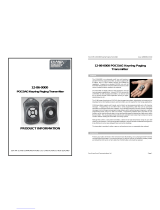
WTE MReX-MB1 is a mini POCSAG & DMR messaging transmitter that can send alphanumeric messages to pagers, smartphones, and DMR radios. It's ideal for sending short messages to field personnel, alerting teams to critical events, or providing status updates. With its compact size and long battery life, the MReX-MB1 is perfect for use in a variety of applications, including construction, manufacturing, healthcare, and public safety.
WTE MReX-MB1 is a mini POCSAG & DMR messaging transmitter that can send alphanumeric messages to pagers, smartphones, and DMR radios. It's ideal for sending short messages to field personnel, alerting teams to critical events, or providing status updates. With its compact size and long battery life, the MReX-MB1 is perfect for use in a variety of applications, including construction, manufacturing, healthcare, and public safety.


-
 1
1
-
 2
2
-
 3
3
-
 4
4
-
 5
5
-
 6
6
-
 7
7
-
 8
8
-
 9
9
-
 10
10
-
 11
11
-
 12
12
-
 13
13
-
 14
14
-
 15
15
-
 16
16
-
 17
17
-
 18
18
-
 19
19
-
 20
20
-
 21
21
-
 22
22
-
 23
23
-
 24
24
-
 25
25
-
 26
26
-
 27
27
-
 28
28
-
 29
29
-
 30
30
-
 31
31
-
 32
32
-
 33
33
-
 34
34


WTE MReX-MB1 is a mini POCSAG & DMR messaging transmitter that can send alphanumeric messages to pagers, smartphones, and DMR radios. It's ideal for sending short messages to field personnel, alerting teams to critical events, or providing status updates. With its compact size and long battery life, the MReX-MB1 is perfect for use in a variety of applications, including construction, manufacturing, healthcare, and public safety.
Ask a question and I''ll find the answer in the document
Finding information in a document is now easier with AI
Other documents
-
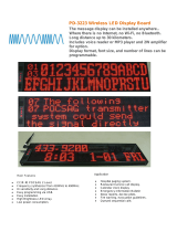 Wireless Devices Inc PD-3223 User manual
-
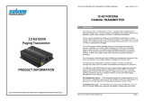 Salcom 12-62 POCSAG Product information
-
 Salcom 12-86-5000 Product information
-
WAGO Servo stepper controller 70 V / 7.5 A 6IN, 2OUT User manual
-
-
NXP DSP56721 User guide
-
Toshiba VF-MB1/S15 User manual
-
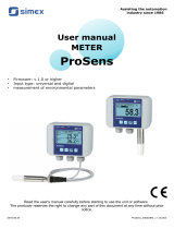 Simex ProSens QM-422 Owner's manual
-
-
Supermicro X8OBN-CPU User manual


