Page is loading ...

Series X Kegerator Instruction Manual
Page 1 of 31 www.KegLand.com.au Last Updated 08/12/2023 10:34 AM
Series X Kegerator
Instrucon Manual
KegLand Distribution PTY LTD
www.KegLand.com.au

Series X Kegerator Instruction Manual
Page 2 of 31 www.KegLand.com.au Last Updated 08/12/2023 10:34 AM
Watch our helpful instruconal YouTube Videos
Video instrucons now available. The KegLand YouTube Channel
(hps://www.youtube.com/KegLand). You can nd the link on our website
www.KegLand.com.au
If there is any part of these videos above that you do not understand or you cannot access please
call or email www.KegLand.com.au or your nearest KegLand Distributor for more assistance.
ENSURE THERE IS OVER 100mm CLEARANCE ON EITHER SIDE OF THE FRIDGE TO ALLOW
FOR ADEQUATE AIR FLOW AND VENTILATION
IF
FRIDGE HAS JUST BEEN MOVED DO NOT TURN ON UNLESS IT HAS BEEN STANDING
UPRIGHT FOR ATLEAST 24 HOURS. FAILURE TO DO SO WILL VOID WARRANTY. STAND
FRIDGE IN THE UPRIGHT POSITION FOR 24 HOURS BEFORE PLUGGING INTO MAINS
POWER SOCKET
CO
2
GAS CAN BE DANGEROUS.
MAKE SURE TO ALWAYS USE CO
2
IN A WELL
-
VENTILATED SPACE.
NEVER EXCEED 40PSI ON YOUR KEG SYSTEM.
FLUSH OUT CHEMICALS FROM YOUR BEER LINE COMPLETELY BEFORE TAPPING KEG.
ALWAYS THOROUGHLY CHECK FOR GAS LEAKS ONCE YOU HAVE SET UP YOUR SYSTEM.

Series X Kegerator Instruction Manual
Page 3 of 31 www.KegLand.com.au Last Updated 08/12/2023 10:34 AM
Contents
Keg Types ........................................................................................................................................ 5
1. Commercial Style Kegs ...................................................................................................... 5
How to Use Keg Couplers ................................................................................................... 6
Alternative Ways to Connect EVABarrier Hose to a Keg Coupler ......................... 6
2. Homebrew style (Cornelius) Kegs ................................................................................... 7
Attaching EVABarrier Hose to a Barbed Disconnect............................................... 9
Attaching EVABarrier Hose to an MFL Disconnect................................................... 7
Removing EVABarrier Hose from a duotight Fitting ............................................... 8
Beer Line Diameter and Length Correlation.................................................................... 9
Balancing Your Keg System with CO2 .......................................................................... 10
Items Included ...................................................................................................................... 11
Single Tap Font Kit ........................................................................................................... 11
Double Tap Font Kit ......................................................................................................... 11
Triple Tap Font Kit ............................................................................................................ 12
Quadruple Tap Font Kit .................................................................................................. 12
Installation Steps.................................................................................................................. 13
Step 1. Preparation .......................................................................................................... 13
Step 2. Castor Wheels Installation................................................................................ 13
Step 3. Chrome Plated Guard Rail Installation ......................................................... 13
Step 4. CO2 Cylinder Bracket Installation (optional) ............................................... 13
Step 5. CO2 Cylinder Bracket Installation (if applicable)........................................ 13
Step 6. Installing MK4 Regulator onto the CO2 Cylinder ........................................ 13
Step 7. Attach the 5mm x 8mm ID EVABarrier Gas Hose to the Regulator ........ 14
Step 8. Feed the 5mm x 8mm EVABarrier Hose into the Fridge............................ 14
Step 9. Setting up the EVABarrier Gas Line for a Single Tap Font ...................... 15
Step 10. Setting up the EVABarrier Gas Line for a Dual, Triple or Quad Font... 15
Step 11. Assembling Single, Double and Triple Tap Fonts ..................................... 16
Step 12. Assembling a Quadruple Tap Font .............................................................. 17
Step 13. Attach the Tap to the duotight Compatible Short Shank ........................ 17
Step 14. IMPORTANT Perform a CO2 Leak/Pressure Test........................................ 18
Installation Diagrams ......................................................................................................... 19

Series X Kegerator Instruction Manual
Page 4 of 31 www.KegLand.com.au Last Updated 08/12/2023 10:34 AM
1. Single Tap Commercial Keg Series X Installation Diagrams .......................... 19
2. Single Tap Cornelius Ball Lock Keg Series X Installation Diagram ............... 20
3. Double Tap Series X Installation Diagram.......................................................... 21
4. Triple Tap Series X Installation Diagram ............................................................ 22
5. Quadruple Tap Series X Installation Diagram ................................................... 23
Adjusting the Set Temperature ......................................................................................... 24
Temperature Calibration .................................................................................................... 24
Minimum Clearance Required Around the Series X..................................................... 24
Troubleshooting Issues ....................................................................................................... 24
Beer is too frothy or no beer pours when the tap is opened ................................. 24
Kegerator is not cooling to the set temperature....................................................... 25
Warranty (Australia)............................................................................................................ 28

Series X Kegerator Instruction Manual
Page 5 of 31 www.KegLand.com.au Last Updated 08/12/2023 10:34 AM
Keg Types
Prior to seng up the kegerator it is important to understand the dierence between the two
categories of kegs that exist and the ngs which are required to carbonate and dispense from
these. You will need to match the ngs to the keg type you are using. There are two main
categories of kegs which come in mulple sizes.
1. Commercial Style Kegs
Commercial kegs come in a variety of sizes; 20L, 25L, 35L and 50L. The 50L size is the most
common size that you will come across. Commercial kegs come in three main styles; A-type, D-
type and Stype. These three types of commercial kegs can be disnguished by the shape of their
spear (shown below). Within Australia the A-type and D-type kegs are the most common. You will
need to buy the specic keg coupler to t the keg type, make sure that prior to buying a kegerator
that you know which type of 50L keg you will be using and which keg coupler is required to
dispense from this keg.
Once you have matched the correct keg coupler to the keg you will need to set up the
commercial keg coupler. On a keg coupler there is an inlet for gas and an outlet for liquid. The
gas inlet is posioned on a 45-degree angle and the liquid outlet is posioned vercally. It is
important to connect the gas line and beer line to the correct inlet and outlet. This is described
in the image below.
Keg Coupler Assembly
Inside the box of a KegLand keg coupler you will nd two types of one-way check valves; gas duck
bill valve and a liquid torpedo check piece. The duck bill valve is used for the gas inlet and the
torpedo check piece or non-return ball is used for the liquid outlet. In a homebrew seng it may
only be necessary to use a check valve in the gas inlet to prevent liquid owing back in to the
regulator.
A
-
Type Keg
D
-
type Keg
S
-
type Keg

Series X Kegerator Instruction Manual
Page 6 of 31 www.KegLand.com.au Last Updated 08/12/2023 10:34 AM
To install the gas duck bill valve, remove the black EPDM washer from inside the 5/8” duoght
ng on the gas inlet and then insert the gas duck bill valve into the opening (as shown below).
Then screw the duoght ng back onto the coupler. To install the liquid torpedo check piece,
remove the 5/8” duoght ng keeping the black EPDM washer in place, then insert the ball and
cage (in the order shown below) and then nally screw the duoght ng back onto the coupler.
How to Use Keg Couplers
Prior to aaching the keg coupler onto the keg make sure that a gas line is connected to the gas
inlet and this gas line is connected to a regulator and a beer line is connected to the liquid outlet
and this beer line is connected to a tap. Aaching the keg to the keg coupler is usually the last step
of the kegerator setup.
A-type keg coupler: Slide the keg coupler over the groove on the top of the keg then rmly depress
the handle to tap the keg.
IMPORTANT: To t a 50L keg with an A-type keg coupler into a kegerator or if your keg is a DIN
style keg (tall skinny style) you will need to use a Low-prole elbow bend (KL00390).
S-type and D-type keg couplers: Push the coupler into the opening of the spear and then rotate
rmly clockwise to aach the coupler to the spear. Then Firmly depress the handle to tap the
keg. More detailed instrucons on how to assemble and operate a keg coupler can be seen in
this video
hps://www.youtube.com/watch?v=qmDYgCPUDuQ
Alternative Ways to Connect EVABarrier Hose to a Keg Coupler
There are various methods of aaching tubing to a keg coupler other than a duoght ng.
It is highly suggested to use a low-prole elbow bend (KL00390) on the liquid outlet of the keg
coupler. This will result in the keg being a lower prole making it easier to t a 50L keg in the
fridge. You can then either connect a duoght ng (KL06903) to the low-prole elbow bend or
you can convert the keg coupler into a quick disconnect ng.
Remove 5/8 EPDM washer from gas 5/8”
duoght
Insert check valves into keg coupler
GAS
LIQUID

Series X Kegerator Instruction Manual
Page 7 of 31 www.KegLand.com.au Last Updated 08/12/2023 10:34 AM
If you are going to be connuously disconnecng EVABarrier tube from the keg coupler or if you
want the beer line setup in the fridge to remain setup with ball lock disconnects then it is
suggested to screw on ball lock posts onto the keg coupler or low-prole elbow bend allowing
ball lock disconnects to be easily and quickly aached and detached from the coupler. (KL00840,
KL00833)
2. Homebrew style (Cornelius) Kegs
Kegs used for homebrewing come in two main categories; Cornelius kegs and mini kegs. The
Cornelius keg category can be split into two main types; ball-lock and pin-lock. If you have
bought a new or second-hand keg from KegLand then it will be a ball-lock type Cornelius keg.
However, if you have sourced a second-hand keg from elsewhere you will need to determine
which type of Cornelius keg you have. This can be determined by invesgang the type of posts
on the keg. The two dierent types of Cornelius keg posts are shown below:
If you are using mini-kegs then you will need a ball-lock tapping head (KL06972) to dispense from
it, this converts it into a normal ball-lock keg which uses the same ngs as a Cornelius ball-lock
keg.
To carbonate and dispense from a homebrew style keg you will need to use disconnects.
These come in two dierent categories which are specic for ball-lock or pin-lock kegs. Ball-
lock kegs require ball-lock disconnects and pin-lock kegs require pin-lock disconnects.
Liquid Ball Lock Disconnect
Gas Ball Lock Post Disconnect

Series X Kegerator Instruction Manual
Page 8 of 31 www.KegLand.com.au Last Updated 08/12/2023 10:34 AM
Each keg requires a liquid disconnect (black) and a gas disconnect (grey). Due to the design of
the posts on the keg a liquid disconnect can only be used on the black liquid (OUT) post and a
gas disconnect can only be used on the grey gas (IN) post.
Disconnects can either include a duoght ng, have a barb or have an MFL thread which requires
a duoght ng (KL06880) to connect EVABarrier hose to the disconnect. It is easier to connect a
hose to an MFL disconnect with a duoght ng compared to a barbed disconnect.
Inserting EVABarrier hose into a duotight Ball Lock Disconnect
Ensure the EVABarrier hose is cut straight and cleanly with a Stanley knife or 2 in 1 tube cuer
(KL07689). Firmly push the EVABarrier hose into the opening of the duoght disconnect. Make
sure that the hose is pushed in past the two internal o-rings to its full depth. Then check for a
good connecon by gently pulling back on the hose. If the hose comes out of the ng, reinsert
into the disconnect ensuring the hosing is pushed far enough into the ng.
Inserting EVABarrier Hose into an MFL Ball Lock Disconnect
Screw a duoght 8mm x FFL (KL06880) onto the MFL disconnect. Ensure that the end of the
EVABarrier hose is cut straight with no burs. The best way to ensure a straight cut is to use a tube
cuer (KL07689) or a very sharp Stanley knife. Then simply push the EVABarrier hose rmly into
the opening of the duoght ng and then pull back slightly to ensure the hose is held in place.
Removing EVABarrier Hose from a duotight Fitting
Simultaneously push the collet in while pulling the EVABarrier hose out of the duoght ng.
Once the hose is removed cut the burred end o with a tube cuer or Stanley knife to produce
a clean straight cut, this aids with forming an airght seal.

Series X Kegerator Instruction Manual
Page 9 of 31 www.KegLand.com.au Last Updated 08/12/2023 10:34 AM
A 7 in 1 spanner tool (KL07672) can also be used to remove hosing from duoght ngs by
inserng the hose into the groove and using the tool to press in on the collet as the hose is pulled
back on.
Inserting EVABarrier Hose into a Barbed Disconnect
Push the barb into the EVABarrier hose unl the whole barb has been inserted into the hose. The
beer line supplied in the font kits is 4mm ID which may be dicult to push over the barb. If you
are unable to push the beer line over the barb then you may need to stretch the internal diameter
of the hose. This can be done by heang the EVABarrier tube in hot (not boiling) water and then
inserng needle nose pliers into the hose and opening the needle nose pliers to stretch the
opening of the hose. This will then allow you to insert the barb into the EVABarrier tubing.
To ensure it doesn’t leak you will need to use a stepless clamp (KL06682) to secure the tubing
onto the barb. Stepless clamps are preferred to worm-style clamps as they clamp in a perfect
circle prevenng the tubing from being pinched which can result in it leaking. To use a stepless
clamp it is suggested to use a clamp tool (KL07054) to crimp the stepless clamp closed.
Alternavely, you can use wire cuers to crimp the clamp closed.
Attaching a Ball Lock Disconnect to a Keg Post
Firstly, ensure you have EVABarrier aached to the ball lock disconnect which is connected to a
tap or gas regulator. Then pull up on the collar of the ball lock disconnect as you push the ball
lock disconnect onto the correct keg post.
Beer Line Diameter and Length Correlation
To ensure you get a consistent pour with the correct amount of head it is important to ensure
the length of beer is correlated with the internal diameter of the EVABarrier hose. The suggested
length of beer line for each internal diameter is outlined below:
Internal diameter
Length
4mm
1.5 metres – 2 metres
5mm
2 metres – 3 metres
6mm
3 metres – 4 metres

Series X Kegerator Instruction Manual
Page 10 of 31 www.KegLand.com.au Last Updated 08/12/2023 10:34 AM
The KegLand font kits come with pre-cut beer and gas line. Each secon of beer line is 4mm ID and
approximately 1.5 metres in length. This should not need to be cut down.
If you are cung your own lengths of beer line then it is best to start at the higher end of the
length range and then cut the beer line down unl you reach your desired pour speed. For
example, if you are using 4mm ID beer line then start with 2m of length and cut down gradually
unl you reach your desired pour speed.
4mm ID beer line is oen the best choice for use in kegerators as it means that less length of
tube can be used and hence a less cluered fridge. It also reduces the amount of beer sing in
the beer lines.
Internal diameter
Length
Beer per meter in
line
Total beer in line
4 mm
1.5 m
12.5 mL
18.75 mL
5 mm
2 m
20 mL
40 mL
6 mm
3 m
28 mL
84 mL

Series X Kegerator Instruction Manual
Page 11 of 31 www.KegLand.com.au Last Updated 08/12/2023 10:34 AM
Since 4mm ID beer line is recommended and this can be dicult to push over a barb then it is
highly suggested to use duoght ngs which are just as easy to use for 4mm ID beer line as
they are for 5mm ID beer line.
Balancing Your Keg System with CO2
To produce the perfect pour, you need to balance a number of variables including beer line
length, carbonaon level of the beer and storage temperature of the keg. The carbonaon level
of the beer is correlated with the temperature of the keg as a lower temperature results in more
CO2 being dissolved into the beer and hence a more carbonated beer at the same CO2 pressure.
For most styles of beer, you should be aiming for a carbonaon level of between 2.3-2.8 volumes
of carbonaon with the average carbonaon level being 2.6 volumes (if you are unsure of the
carbonaon level of the beer i.e. if it is a commercial keg then assume it is at 2.6 volumes of
carbonaon).
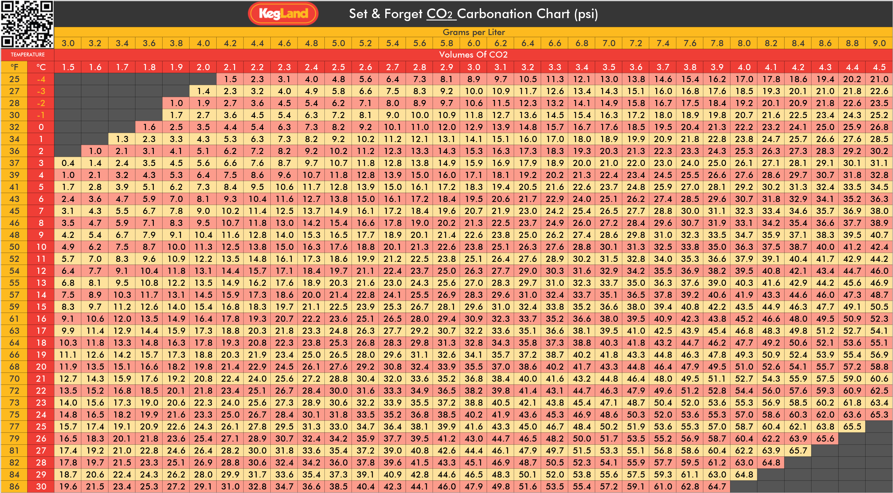
To achieve a specic carbonaon level during carbonaon or priming refer to the table in the link
below and correlate the temperature of the fridge with the desired carbonaon level. The
storage temperature of most beers should be between 0°C and 3°C (2°C is a good middle
ground). Then dispense at a pressure that is 10% above the carbonaon level achieved during
carbonaon. Hence if you desire a carbonaon level of 2.6 volumes of carbonaon and the
fridge temperature is 2°C then carbonate at approximately 11 PSI and dispense at approximately
12PSI.
hps://www.kegland.com.au/media/images/KegLand%20Set%20&%20Forget%20CO2%20Carbo
na on%20Chart.png
NOTE: Do not try to x a slow or fast pour rate by adjusng the dispensing pressure. This will result
in your beer either going at or over carbonated. It is best to adjust the beer line length and
diameter. If you think that you have over carbonated your beer you may need to release the
pressure in the keg and then set it to your desired pressure according to the carbonaon chart. Do
not release pressure in the keg by pulling the PRV on the regulator as this can result in liquid
being pulled into the regulator and potenally causing damage to the regulator.
To produce lightly carbonated beers such as English ales you can adjust the carbonaon and
dispensing pressure for that keg using a dual pressure regulator if you have mulple kegs in
the fridge and want to keep the fridge at a low temperature. Alternavely, if you only have
lightly carbonated beers in the fridge then you can increase the temperature of the fridge and
keep the carbonaon and dispensing pressure around 11 and 12 PSI respecvely.

Series X Kegerator Instruction Manual
Page 12 of 31 www.KegLand.com.au Last Updated 08/12/2023 10:34 AM
Items Included
The Series X base fridge with regulator includes the following items:
1 x MK4 Regulator (KL07429)
1 x Wire shelf
1 x Black plasc wrap around drip tray (KL00192)
4 x Castor wheels
16 x Castor wheel screws
1 x CO2 cylinder holder (designed to suit 2.6Kg CO2 cylinder)
1 x Chrome Plated Guard Rail
If you have bought a KegLand font kit they include the following items:
Single Tap Font Kit
1 x single tap – stainless steel font
1 x duoght compable short shank
1 x duoght 6.5mm x 8mm reducer
1 x Black plasc tap handle
1 x Pre-cut 4mm ID x 8mm OD EVABarrier
beer line
1 x Pre-cut 5mm ID x 8mm OD EVABarrier gas
line
4 x Metric M5 Stainless screws
1 x 7 in 1 faucet tap wrench/spanner
1 x double tap – stainless steel font

Series X Kegerator Instruction Manual
Page 13 of 31 www.KegLand.com.au Last Updated 08/12/2023 10:34 AM
Double Tap Font Kit
2 x duoght compable short shank
2 x duoght 6.5mm x 8mm reducer
2 x Black plasc tap handle
2 x Pre-cut 4mm ID x 8mm OD EVABarrier
beer line
1 x Pre-cut 5mm ID x 8mm OD EVABarrier gas
line
4 x Metric M5 Stainless screws
1 x 7 in 1 faucet tap wrench/spanner
1 x duoght 8mm push in tee piece
Triple Tap Font Kit
1 x triple tap – stainless steel font
3 x duoght compable short shank
3 x duoght 6.5mm x 8mm reducer
3 x Black plasc tap handle
3 x Pre-cut 4mm ID x 8mm OD EVABarrier
beer line
1 x Pre-cut 5mm ID x 8mm OD EVABarrier gas
line
4 x Metric M5 Stainless screws
1 x 7 in 1 faucet tap wrench/spanner
2 x duoght 8mm push in tee piece
Quadruple Tap Font Kit
1 x quadruple tap – stainless steel font
4 x duoght compable short shank
4 x duoght 6.5mm x 8mm reducer
4 x Black plasc tap handle
4 x Pre-cut 4mm ID x 8mm OD EVABarrier
beer line
1 x Pre-cut 5mm ID x 8mm OD EVABarrier gas
line
4 x Metric M5 Stainless screws
1 x 7 in 1 faucet tap wrench/spanner
3 x duoght 8mm push in tee piece

Series X Kegerator Instruction Manual
Page 14 of 31 www.KegLand.com.au Last Updated 08/12/2023 10:34 AM
Installation Steps
Step 1. Preparation
• Remove all items from inside the kegerator
• Ensure all items have been included
• Remove any protecve plasc from the kegerator before rst use.
• Check for any damage which has occurred during transit including any liquid or oil marks
on the inside of the packaging.
Step 2. Castor Wheels Installation
• Make sure the kegerator is empty
• Carefully lay the kegerator on its side on a so surface such as carpet, cardboard or a towel.
• Unscrew the feet from the base of the kegerator
• Aach each castor wheel to the base of the kegerator using 4 screws (this may require
screws to be removed from the mounng holes)
• The two locking castor wheels should be installed towards the front of the kegerator
• Posion the kegerator back upright and leave for minimum 1 hour before turning it on to
allow the refrigerant gas to sele.
NOTE: The screw holes may be lled with foam and have a foil covering. If this is the case push
and thread the screws through the foam or foil. The screw will then catch on the thread allowing
it to be screwed in completely.
Step 3. Chrome Plated Guard Rail Installation
• Posion the guard rail such that the feet line up with the holes in the top of the kegerator
• Push the feet of the railing rmly into the holes
Step 4. CO2 Cylinder Bracket Installation (optional)
• Align the four holes in the bracket with the four studs on the back of the kegerator.
• Insert the studs into the holes and then push the bracket down rmly to secure it.
Step 5. CO2 Cylinder Bracket Installation (if applicable)
CO2 cylinder is purchased separately
• Place the CO2 cylinder on the base of the bracket
• Secure the CO2 cylinder to the bracket using the strap on the bracket.
NOTE: Do not secure a 6.0Kg CO2 cylinder on the bracket as it is only rated to hold 2.6Kg CO2
cylinders. If you have a 6.0Kg CO2 cylinder place it on the oor in close proximity to the kegerator.
Step 6. Installing MK4 Regulator onto the CO2 Cylinder
• Ensure the CO2 cylinder is o by turning the cylinder valve handle clockwise.
• Ensure the regulator dial is completely unscrewed and ensure there is a nylon regulator
washer between the type 30 nut and stem and the CO2 cylinder.
• Hand ghten the nut and stem onto the CO2 cylinder then ghten further with a 7 in 1
faucet tap wrench/spanner.

Series X Kegerator Instruction Manual
Page 15 of 31 www.KegLand.com.au Last Updated 08/12/2023 10:34 AM
Steps 7 to 10 will describe how to setup your gas line in your fridge allowing you
to store your gas cylinder externally.
Step 7. Attach the 5mm x 8mm ID EVABarrier Gas Hose to the Regulator
Aaching hosing to a duoght ng (standard)
• The Mk4 regulator provided in a Series X fridge comes as standard with an 8mm x FFL
duoght Fing (KL06880).
• Make sure the end of the 5mm x 8mm EVABarrier hose doesn’t have any burs and is cut
straight and cleanly. Push the 5mm x 8mm EVABarrier hose line rmly into the duoght
ng on the regulator and ensure it is secure.
Aaching a barb to the regulator (oponal)
• If you prefer to use barbed ngs rather than a duoght ng you can unscrew the
duoght ng and then screw a swivel nut and barb (KL03025) onto the male thread on
the regulator
• Push the 5mm EVABarrier gas line over the outlet barb and secure with a stepless clamp
Step 8. Feed the 5mm x 8mm EVABarrier Hose into the Fridge
• Unscrew one of the caps on the back of the Series X and feed the EVABarrier gas line
through the hole.
Alternavely, you can convert the back of the fridge into a quick disconnect using parts which are
sold separately (oponal, if you don’t want to do this skip to step 9):
• Unscrew one of the PET caps on the back of the fridge where you want the gas hose to
enter the fridge
• Aach a 6.5mm x 8mm reducer (KL07481) to the barb on a plasc carbonaon and line
cleaning cap (KL10788).
• Screw the carbonaon and line cleaning cap onto the gas inlet thread on the back of the
Series X.
• Cut the 5mm x 8mm EVABarrier gas hose to length. Cut it such that there is enough length
to reach from the regulator to the carbonaon and line cleaning cap.
• Push the 5mm x 8mm EVABarrier gas hose that is connected to the regulator into a gas
ball lock-disconnect and 8mm x FFL duoght ng (KL02967 and KL06880)
• Push the grey (gas) ball-lock disconnect onto the carbonaon and line cleaning cap
• Push the other length of 5mm x 8mm EVABarrier gas hose into the duoght ng on the
carbonaon and line cleaning cap

Series X Kegerator Instruction Manual
Page 16 of 31 www.KegLand.com.au Last Updated 08/12/2023 10:34 AM
Step 9. Setting up the EVABarrier Gas Line for a Single Tap Font
(If using a dual, triple or quadruple font skip to step 10)
• Aach the gas line onto a keg coupler or grey ball lock disconnect via either the barb or a
duoght ng (KL06880).
Step 10. Setting up the EVABarrier Gas Line for a Dual, Triple or Quad
Font
(If using a single font skip to step 11)
Double font
• Cut approximately 1m o the end of the 5mm x 8mm EVABarrier gas hose.
• Cut this 1m secon of 5mm x 8mm EVABarrier hose into two 50cm lengths.
• Push the two 50cm lengths of 5mm x 8mm EVABarrier gas hose in to the duoght tee-
piece.
• Aach the two 50cm lengths of EVABarrier gas line to grey (gas) ball lock disconnects
• Push the remaining length of 5mm x 8mm EVABarrier hose into the duoght ng on your
regulator and insert this hose into one of the gas inlet holes on the back of the fridge and
push this hose into the remaining opening on the duoght tee piece.
Triple font
• Cut approximately 10cm o the end of the 5mm x 8mm EVABarrier gas hose.
duoght
-
mm x 8mm reducer
(
6.5
KL0748
1
)
Plasc carbonaon & line cleaning cap (
KL1078
8
)
Grey (gas) ball lock disconnect
(
KL0296
7
,
1
KL0300
,
0
KL0901
)
duoght
–
mm x FFL
(
8
0
KL0688
)

Series X Kegerator Instruction Manual
Page 17 of 31 www.KegLand.com.au Last Updated 08/12/2023 10:34 AM
• Join the two duoght tee-pieces together using this 10cm joiner you just cut as shown
below:
• Cut three 50cm lengths of 5mm x 8mm EVABarrier gas hose.
• Aach the EVABarrier gas hose that is fed through the hole in the back of the fridge into
one of the duoght tee-pieces.
• Push the three 50cm lengths of EVABarrier gas line into the remaining openings on the
duoght tee-pieces.
• Aach each 50cm length of 5mm x 8mm EVABarrier gas hose from the duoght pieces to
a grey (gas) ball lock disconnect.
Quadruple font
• Cut approximately 20cm o the end of the 5mm x 8mm EVABarrier gas line and then cut
this 20cm length in half, resulng in two 10cm joiner pieces.
• Join the three duoght tee-pieces together using the two cut joiner pieces, as shown
below:
• Cut approximately 2m o the end of the 5mm x 8mm EVABarrier hose.
• Cut this 2m secon into four 50cm lengths.
• Aach the 5mm x 8mm EVABarrier hose that is fed through the hole in the back of the
fridge into one of the duoght tee-pieces.
• Aach the four 50cm lengths of 5mm x 8mm EVABarrier hose into the remaining outlets
of the duoght tee-pieces.
• Aach each 50cm length of EVABarrier hose to a grey (gas) ball lock disconnect.
Step 11. Assembling Single, Double and Triple Tap Fonts
(If using a quadruple font skip to step 12)

Series X Kegerator Instruction Manual
Page 18 of 31 www.KegLand.com.au Last Updated 08/12/2023 10:34 AM
• Remove the cap from the top of the font and ensure the font collar is present at the base
of the font prior to aaching any duoght compable short shanks.
• Feed the length of beer line through the tap hole on the front of the font and feed the
beer line through the slimline nut and convex collet on the inside of the font.
• Push a 6.5mm x 8mm reducer onto the back of the duoght compable short shank.
• Feed the tail and thread of the duoght compable short shank through the tap hole and
align the curvature of the shank and the concave collet with the curvature of the font.
• Push each length of beer line into a 6.5mm x 8mm reducer which is aached to a short
shank
• Tighten the slimline nut onto the thread of the duoght compable short shank to secure
the shank to the font tower.
• Repeat for all other duoght compable short shanks and beer lines
• Feed the beer lines from the duoght compable short shanks into the kegerator.
• Aach the font to the top of the kegerator by screwing the font onto the font mounng
points using four metric M5 stainless steel screws.
• Aach each EVABarrier beer line to a liquid ball lock disconnect or keg coupler
Step 12. Assembling a Quadruple Tap Font
• First, aach the font to the top of the kegerator using four metric M5 stainless
steel screws. The mounng points can be found on the inside of the font and
can be aached using a long screwdriver or exible drill bit.
• Then aach the duoght compable short shanks, duoght 6.5mm x 8mm
reducer and beer line to the font tower as described in step 11. It is easiest to
aach the shanks to the font tower in the order shown to the right:
• Feed the beer lines from the duoght compable short shanks into the
kegerator.
• Aach each EVABarrier beer line to a ball lock disconnect or keg coupler
Step 13. Attach the Tap to the duotight Compatible Short Shank
• Hand-ghten the tap (sold separately) onto the duoght compable short
shank
• Tighten the short shank collar onto the tap using a 7 in 1 tap wrench/spanner.

Series X Kegerator Instruction Manual
Page 19 of 31 www.KegLand.com.au Last Updated 08/12/2023 10:34 AM
• Repeat this for all taps and short shanks
Step 14. IMPORTANT Perform a CO2 Leak/Pressure Test
Performing a leak test is essenal to make sure the system holds pressure and there are no CO 2
leaks between any connecons which could result in your CO2 cylinder becoming drained over
me.
This can be performed two dierent ways:
Method 1 – Pressure decay test
Step 1. Aach all disconnects to an empty keg.
Step 2. Set the pressure on the regulator at 20 PSI.
Step 3. Turn the CO2 cylinder valve handle o
Step 4. Wait two hours and check that the pressure reading on the right pressure gauge on the
regulator has not changed.
If the pressure reading has not changed then there are no leaks in the system. If it has dropped
then use method 2 to determine the posion of the leak.
NOTE: Even if the system passes a pressure test is sll may be a good idea to perform method 2 as
well.
Method 2 – Detergent bubble test
Step 1. Aach all disconnects to an empty keg.
Step 2. Set the pressure on the regulator at 20 PSI.
Step 3. Sponge a detergent soluon onto all connecons or potenal places for leaks to occur.
This includes:

Series X Kegerator Instruction Manual
Page 20 of 31 www.KegLand.com.au Last Updated 08/12/2023 10:34 AM
• The connecon between the CO2 cylinder and the regulator
• All duoght connecons including the 8mm x FFL duoghts connected to the regulator,
ball lock disconnects and keg coupler, the 6.5mm x 8mm duoght reducers connected to
the short shanks and the 8mm duoght tee pieces.
• Around ball lock disconnects and keg couplers when they are connected to the keg
• Around the lid of a Cornelius keg.
• Make sure to remove the ball lock disconnects from the posts of the ball lock keg and
check the post itself for leaks.
IMPORTANT: Do not spray any duoght ngs with Stellarsan or phosphoric acid soluon to
perform a leak test.
Aer locang a leak using the detergent leak test perform another pressure test to ensure the
system holds pressure.
Installation Diagrams
Please note that the below diagrams are not the only way to plumb up a series X as gas manifolds
can be used instead of duoght tee pieces for example.
1. Single Tap Commercial Keg Series X Installation Diagrams
1.1
Commercial Keg with
duoght
Fings
1.2
Commercial Keg with Low Prole Elbow Bend and Ball Lock Posts
/


