

TM
TM
Page <2> V1.005/07/23
Newark.com/exclusive-brands
Farnell.com/exclusive-brands
Element14.com/exclusive-brands
Table of Contents
1 - Introduction.............................................................................................................................................................................4
2 - Safety Information ..................................................................................................................................................................4
3 - Packing Lists ..........................................................................................................................................................................5
3.1 - Standard Accessories ................................................................................................................................................ 5
3.2 - Optional Accessories .................................................................................................................................................. 5
4 - Specications .........................................................................................................................................................................5
5 - Structure Description .............................................................................................................................................................. 7
5.1 - Back View................................................................................................................................................................... 7
5.2 - Front View .................................................................................................................................................................. 8
5.3 - Assembly drawing ...................................................................................................................................................... 8
5.4 - Interface .....................................................................................................................................................................9
6 - Before You Start .....................................................................................................................................................................9
6.1 - How to Charge the Battery ......................................................................................................................................... 9
6.1.1 - Battery Charger Base ..................................................................................................................................... 9
6.1.2 - AC Power Socket ........................................................................................................................................... 9
6.2 - Power On and O..................................................................................................................................................... 10
6.3 - Main Interface .......................................................................................................................................................... 10
6.4 - Optical Lens .............................................................................................................................................................10
6.5 - Focus ....................................................................................................................................................................... 11
6.6 - Shutter ......................................................................................................................................................................12
6.7 - Temperature Measurement ...................................................................................................................................... 12
6.8 - Emissivity Adjustment .............................................................................................................................................. 12
6.9 - Reected Temperature ............................................................................................................................................. 12
6.10 - Thermal Imager Reporter Software ........................................................................................................................ 13
7 - Menus...................................................................................................................................................................................13
7.1 - Main Menu ............................................................................................................................................................... 13
7.2 - Image Menu .............................................................................................................................................................14
7.2.1 - Image Mode ................................................................................................................................................. 14
7.2.2 - Image Palette ............................................................................................................................................... 14
7.2.3 - Image Adjustment ........................................................................................................................................ 17
7.2.4 - Image Setting ............................................................................................................................................... 18
7.2.5 - Zoom and Rotation ....................................................................................................................................... 19

TM
TM
Page <3> V1.005/07/23
Newark.com/exclusive-brands
Farnell.com/exclusive-brands
Element14.com/exclusive-brands
7.3 - Measurement Menu ................................................................................................................................................. 19
7.3.1 - Point Measurement ...................................................................................................................................... 19
7.3.2 - Line Measurement ....................................................................................................................................... 20
7.3.3 - Area measurement .......................................................................................................................................21
7.3.4 - Measurement Settings ................................................................................................................................. 22
7.4 - Camera Menu .......................................................................................................................................................... 24
7.4.1 - Snapshot Menu ............................................................................................................................................ 25
7.5 - Video Menu .............................................................................................................................................................. 26
7.6 - Photos Browser ........................................................................................................................................................ 26
7.6.1 - Multi-Photos Browser ................................................................................................................................... 26
7.6.2 - Single-Photos Browser ................................................................................................................................. 27
7.7 - Player Menu .............................................................................................................................................................27
7.8 - Settings Menu .......................................................................................................................................................... 28
7.8.1 - General Page ............................................................................................................................................... 28
7.8.2 - Control Page ................................................................................................................................................ 29
7.8.3 - Photos Page ................................................................................................................................................. 31
7.8.4 - Date & Time Page ........................................................................................................................................ 31
7.8.5 - Info Page ...................................................................................................................................................... 32
7.9 - Factory Settings ....................................................................................................................................................... 32
8 - Fault diagnosis and exclusion .............................................................................................................................................. 33

TM
TM
Page <4> V1.005/07/23
Newark.com/exclusive-brands
Farnell.com/exclusive-brands
Element14.com/exclusive-brands
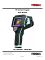
1 - Introduction
Overview
The Thermal Imager is handheld imaging camera used for predictive maintenance, equipment troubleshooting, and verication.
Thermal and visual images are displayed on the LCD and can be saved to a Micro SD Memory card. Transferring images to a
PC is accomplished by removing the SD memory card and connecting it to a PC through the included card reader.
In addition to the features mentioned above, the Thermal Imager provide video recording with audio and play back.
2 - Safety Information
To prevent eye damage and personal injury, do not look into the laser. Do not point laser directly at persons or animals or
indirectly o reective surfaces.
Do not disassemble or do a modication to the Thermal Imager.
Do not point the Thermal Imager (with or without the lens cover) at intensive energy sources, for example devices that emit
laser radiation, or the sun.
This can have an unwanted eect on the accuracy of the camera. It can also cause damage to the detector in the Thermal
Imager.
Do not use the Thermal Imager in a temperature higher than +50°C (+122°F), lower than -20°C (-4°F). High temperature or low
temperature can cause damage to the Thermal Imager.
Only use the correct equipment to discharge the battery.
If you do not use the correct equipment, you can decrease the performance or the life cycle of the battery. If you do not use the
correct equipment, an incorrect ow of current to the battery can occur. This can cause the battery to become hot, or cause an
explosion and injury to persons.
Do not disassemble or do a modication to the battery.
The battery contains safety and protection devices which, if they become damaged, can cause the battery to become hot, or
cause an explosion or an ignition. If there is a leak from the battery and the uid gets into your eyes, do not rub your eyes. Flush
well with water and immediately get medical care.
Do not make holes in the battery with objects. Do not hit the battery with a hammer. Do not step on the battery, or apply strong
impacts or shocks to it.
Do not put the battery in or near a re, or in direct sunlight, or other high-temperature locations. Do not solder directly onto the
battery.
Always charge the battery in the special temperature rang.
The temperature range through which you can charge the battery is 0°c to +50°C(+32°F to +122°F). If you charge the battery
at temperatures out of this range, it can cause the battery to become hot or to break. It can also decrease the performance or
the life cycle of the battery.
Do not get water or salt water on the battery, or permit the battery to get wet.
Clean the case with a damp cloth and a weak soap solution. Do not use abrasives, isopropyl alcohol, or solvents to clean the
case or lens/screen.
Be careful when you clean the infrared lens. Do not clean the infrared lens too vigorously. This can damage the anti-reective
coating.
Avoid condensation
Take the Thermal Imager from cold to hot, it will appear condensation in Thermal Imager. To protect the Thermal Imager, you
should power of the Thermal Imager, wait until the Thermal Imager has become war enough for the condensation to evaporate.
Storage
If you do not use the Thermal Imager, remove the battery from the Thermal Imager, and put the Thermal Imager in cool and dry
environment, if you store Thermal Imager equipped with the battery, the power of the battery will be exhausted.

TM
TM
Page <5> V1.005/07/23
Newark.com/exclusive-brands
Farnell.com/exclusive-brands
Element14.com/exclusive-brands
3 - Packing Lis
3.1 - Standard Accessories
3.2 - Optional Accessories
4 - Specications
Item Quantity Description
Lens 1 eld of view = 20.6° × 15.5°, f = 11mm
Lens 1 eld of view = 10.4° × 7.8°, f = 22mm
Lens 1 eld of view = 6.9° × 5.2°, f = 33mm
Lithium polymer battery 1 7.4V, 2600mAH
Item Quantity Description
Thermal Imager 1
Lens 1 Field of view = 29.8° × 22.6° f = 7.5mm
Lens Cover 1
Led Hood 1
Tripod Base 1
Lithium polymer battery 1 7.4V, 2600mAH
Adaptor 1 Input AC Volts: 100V to 240V. 50/60Hz,
MAX 0.8A Output DC Volts: 12V, 3000mA
Charger 1
Micro SD 1 4GByte
USB cable 1
RCA cable 1
Earphone 1
User manual 1
Warranty Card 1
PC software
Inallation CD 1
Gift box & Carrying case 1
Imaging And Optical Data
Field of view (FOV) / Minimum focus distance 29.8° × 22.6°/ 0.2m
Spatial resolution (IFOV) 3.33mrad
Thermal sensitivity/NETD < 0.08°C @ +30°C (+86°F) / 80 mK
Image frequency 50Hz
Focus mode Manual
Zoom 1-20 × continuous, digital zoom

TM
TM
Page <6> V1.005/07/23
Newark.com/exclusive-brands
Farnell.com/exclusive-brands
Element14.com/exclusive-brands
Rotate 0° - 360°, continuous increased by 1°
Focal length 7.5mm
Focal Plane Array (FPA) / Spectral range Uncooled microbolometer / 8-14µm
IR resolution 160 x 120 pixels
Image Presentation
Display Capacitive Touch screen, 3.5 in. LCD, 320 × 240 pixels
Image modes IR image, visual image, picture in picture, Image Fusion
Picture in Picture IR area on visual image or visual image area on IR
Colour palettes GRAY/GRAYINV IRON/IRONINV/RAINBOW/FEATHER
Measurement
Object temperature range -20°C to +150°C (-4°F to +302°F)
0°C to +400°C (+32°F to +752°F)
Accuracy ±2°C (±3.6°F) or ±2% of reading
Measurement Analysis
Spot 3
Line 2 lines (horizontal and vertical)
Area 3 boxes with max./min./average
Automatic hot / cold detection Auto hot or cold markers
Isotherm Detect high/low temperature/interval
Emissivity correction Variable from 0.01 to 1.0
Measurement corrections Emissivity, ambient temperature, diance,
relative humidity, oset temperature
Storage of Videos
Storage media 4GBytes Micro SD card
Video orage format Standard MPEG-4, 640 × 480@30fps, on memory card > 60 minutes
Video orage mode IR / visual images; simultaneous orage of IR and visual images
Storage of Images
Image orage format Standard JPEG, including measurement data,
on memory card > 1000 pictures
Image orage mode IR/visual images; simultaneous orage of IR and visual images
Set-Up
Laser < Class 2
Set-up commands Local adaptation of units, language, date and time formats,
information of camera
Languages Multinational
Digital Camera
Built-in digital camera 640 × 480 pixels
Built-in digital lens data FOV 62.3°
Data Communication Interfaces
Interfaces USB-mini, audio, Composite Video, Micro SD Slot

TM
TM
Page <7> V1.005/07/23
Newark.com/exclusive-brands
Farnell.com/exclusive-brands
Element14.com/exclusive-brands
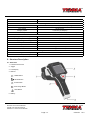
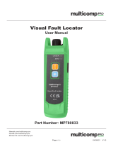
5 - Structure Description
5.1 - Back View
1 - Infrared Camera Lens
2 - Trigger
3 - LCD Display
4 - Buttons
HOME Button
Shutter Button
Power Button
Save Image Button
Laser Button
5 - Battery
USB Data transform between Camera and PC
Video out Composite (PAL and NTSC)
Power System
Battery Lithium Polymer Battery, 4.5 hours operating time
Input voltage DC 9V to 12V
Charging syem In Camera (AC Adapter)
Power management Automatic shutdown and sleep mode (User Selectable)
Environmental Data
Operating temperature range -20°C to +50°C (-4°F to +122°F)
Storage temperature range -40°C to +70°C (-40°F to +158°F)
Humidity (operating and orage) 10% to 90%
Encapsulation IP65
Drop te 2m
Bump 25g (IEC60068-2-29)
Vibration 2g (IEC60068-2-6)
Physical Data
Camera weight, incl. Battery 920g
Camera size (L x W x H) 243 × 103 ×160

TM
TM
Page <8> V1.005/07/23
Newark.com/exclusive-brands
Farnell.com/exclusive-brands
Element14.com/exclusive-brands
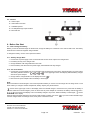
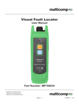
5.2 - Front View
6 - LED Light
7 - Visual Camera
8 - Laser Pointer
9 - Infrared Camera Lens Lock
10 - Infrared Camera Lens
5.3 - Assembly drawing
11 - Liquid Crystal Display Hood
12 - Thermal Imager
13 - Tripod Base
14 - Lens Cap for Infrared Lens

TM
TM
Page <9> V1.005/07/23
Newark.com/exclusive-brands
Farnell.com/exclusive-brands
Element14.com/exclusive-brands
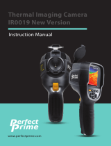
5.4 - Interface
15 - Video Output
16 - USB Cable Connection
17 - Audio/Microphone
18 - AC Adapter/Charger Input Terminal
19 - Micro SD Slot
6 - Before You Start
6.1 - How to Charge the Battery
Before you use the Thermal Imager for the rst time, charge the battery for a minimum of one and one-half hours. The battery
status shows on the three-segment charge indicator.
To charge the battery, use one of the options that follow:
6.1.1 - Battery Charger Base
1 - Connect the ac power supply to the ac wall outlet and connect the de output to the charger base.
2 - Put battery into bay of the charger base.
3 - Charger batteries until charge indicators show ″full″.
4 - Remove battery and disconnect the power supply when batteries are fully charged.
6.1.2 - AC Power Socket
1 - Connect the ac power adapter into an ac wall outlet and connect the DC output to the Thermal Imager’s AC power socket
The battery indicator becomes ″ ″ in the upper right comer of the display while the battery charges
with the AC power adapter.
2 - Charge until the charge indicator on the display becomes ″ ″.
3 - Disconnect AC power adapter when the battery is full charged.
Note:
Make sure that the Thermal Imager is near room temperature before you connect it to the charger. Do not charge in hot or cold
areas. When you charge in extreme temperature, battery capacity may be decreased.
″ ″ Shows in the upper right comer of the display when the Thermal Imager is connected to AC power and the battery is
removed. When the Thermal Imager’s power is o and the AC power adapter is connected, the battery indicator becomes ″
″ in the center of the display to show the battery charger is in process. When the battery is full charged, ″ ″ shows
in the center of the display.
Keep the Thermal Imager attached to the charger until the battery condition icon show ″ ″ If you remove the Thermal Imager
from the charger before a full charge shows, it may have a reduced run-time.

TM
TM
Page <10> V1.005/07/23
Newark.com/exclusive-brands
Farnell.com/exclusive-brands
Element14.com/exclusive-brands
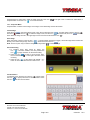
6.2 - Power On and O
To turn the Thermal Imager on or o, push and hold the Power ″ ″ Button for three seconds. When Thermal Imagers power
on, there is another way to power o, do the following:
1 - Push and hold the Power ″ ″ Button for two seconds, popup the menu.
2 - Slide ″ ″to the right, the device will be power o.
When Thermal Imagers power on, Push the Power ″ ″ Button to the LCD
power on or o. If the Screen O feature is on, the LCD power o after the
setting time of inactivity. If the Power o feature is on, the Thermal Imager power
o after the setting time of inactivity.
Note:
Thermal Imager needs sucient warm-up time for the most accurate
temperature measurements and best Image quality. This time can often vary by
environmental conditions. It is best to wait a minimum of 10 minutes if the most
accurate temperature measurement is very important to your application.
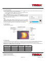
6.3 - Main Interface
The Main Interface Is as follow
6.4 - Optical Lens
The Thermal Imager has 4 kinds of Optical Lens. To change lens, Anti-clockwise rotates the Infrared Camera Lens Lock to
unlock the lens, then pull out lens, put the new lens, clockwise rotates the Infrared Camera Lens Lock to lock lens.
Dierent lens has dierent eld of view (FOV). FOV is the area that your Imager can see at distance. This table lists the
horizontal FOV, vertical FOV and IFOV for every lens.
Focal Length Horizontal FOV Vertical FOV IFOV
7.5mm 29.8° 22.6° 3.33mrad
11mm 20.6° 15.5° 2.27mrad
22mm 10.4° 4.8° 1.14mrad
33mm 6.9° 5.2° 0.76mrad

TM
TM
Page <11> V1.005/07/23
Newark.com/exclusive-brands
Farnell.com/exclusive-brands
Element14.com/exclusive-brands
IFOV (Instantaneous Field of View) is the smallest detail with in the FOV that can be detected or seen at a set distance, the
unit rad. The formula is this:
IFOV = (Pixel Size)/(Lens focal length);
D:S theoretical ( = 1/IFOV theoretical) is calculated spot size based on the pixel size of the thermal Imager detector array and
lens focal length.
Example: If Thermal Imager uses 7.5mm lens, because the Pixel Size of detector is 25um. Horizontal FOV
is 29.8°, Vertical FOV is 22.6°, the IFOV is
25um/7.5mm = 3.33mrad;
D:S theoretical( = 1/ IFOV theoretical) = 300:1
Spot Size= 100.00cm*100.00cm
(Based upon IFOVtheoretical)
D:S theoretical = 300:1
IFOV = instantaneous Field of view
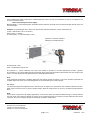
D:S measure ( = 1/IFOV measure) is the spot size needed to provide an accurate temperature measure. Typically,
D:S measure is 2 to 3 times smaller than D:S theoretical, which means the temperature measurement area of the target need
to be 2 to 3 times larger than that determined by the calculated theoretical D:S.
Note:
IFOV theoretical represents the smallest objects that the Thermal Imager can detect or see. IFOV measure represents the
smallest object form which an accurate temperature can be measured by the Thermal Imager.
6.5 - Focus
The Thermal Imager has IR-OptiFlex focus in manual mode. To adjust focus, clockwise or Anti-clockwise rotates the IR Lens.
When target comes into focus, it shows a sharper image. When the target moves out of focus, the thermal image becomes
blurry.
Note:
Correct focus is important in all imaging applications. Correct focus makes sure that the infrared energy is correctly directed
onto the pixels of the detector. Without the correct focus, the thermal image can be blurry and the radiometric data will be
inaccurate. Out-of-focus infrared images are frequently unusable or of little value.

TM
TM
Page <12> V1.005/07/23
Newark.com/exclusive-brands
Farnell.com/exclusive-brands
Element14.com/exclusive-brands
6.6 - Shutter
The thermal Image of the Thermal Imager becomes blurry, when the Thermal Imager no correcting after some minutes or the
Thermal Imager changes target. To get ne thermal Image, the Thermal Imager need to correct.
The Thermal Imager has two mode for correcting, Manual and Auto Mode. In Manual Mode, push the ″ ″ Shutter button, the
Thermal Imager will correct. In Auto Mode, the Thermal Imager can open Auto Shutter feature in Settings Menu.
6.7 - Temperature Measurement
All objects radiate infrared energy. The quantity of energy radiated is base on the actual surface temperature and the surface
emissivity of the object. The Thermal Imager senses the infrared energy from the surface of the object and uses this data to
calculate an estimated temperature value. Many common objects and materials such as painted metal, wood, water, skin and
cloth are very good at radiating energy and it is easy to get relatively accurate measurements. For surfaces that are good
at radiating energy (high emissivity), the emissivity factor is >=0.90. This simplication does not work on shiny surfaces or
unpainted metals as they have an emissivity of <0.6. These materials are not good at radiating energy and are classied as low
emissivity. To more accurately measure materials with a low emissivity, an emissivity correction is necessary. Adjustment to the
emissivity setting will usually allow the Thermal Imager to calculate a more accurate estimate of the actual temperature. More
information please see Emissivity Adjustment to get the most accurate temperature measurements.
6.8 - Emissivity Adjument
The correct emissivity value is important to make the most accurate temperature measurement. Emissivity of a surface can
have a large eect on the apparent temperatures that the Thermal Imager observes. Understanding the emissivity of the
surface, but may not always, allow you to obtain more accurate temperature measurements.
Note:
Surfaces with an emissivity of <0.60 make reliable and consistent determination of actual temperature problematic. The lower
the emissivity, the more potential error is associated with the Imager’s temperature measurement calculations. This is also true
even when adjustments to the emissivity and reected background adjustments are performed properly.
Emissivity is set directly as a value or from a list of emissivity values for some common materials. The global emissivity displays
in LCD Screen as E=x.xx.
The following table gives typical emissivity of important materials.
Material Emissivity
Asphalt 0.95
Concrete 0.95
Hard plaster 0.90
Wood {natural) 0.93
Lime Stone 0.98
Ballast chipping 0.95
Paper (every colour) 0.95
Plastics non transparent 0.95
Tissue (fabric) 0.95
Sand 0.90
Glass wool 0.90
Melted asphalt 0.93
Screed/attic/pavement 0.93
Foamed polystyrene 0.94
Material Emissivity
Drywall 0.95
Render 0.94
Smoothing cement 0.90
Lacquer 0.92
Latex paint 0.97
Wallpaper 0.93
Tilling 0.93
Parquet oor 0.90
Laminate 0.90
PVC-Floor 0.92
Brick 0.93
Cli 0.97
Roong cardboard 0.93
Stucco 0.91

TM
TM
Page <13> V1.005/07/23
Newark.com/exclusive-brands
Farnell.com/exclusive-brands
Element14.com/exclusive-brands
6.9 - Reected Temperature
Using the oset factor, the reection is calculated out due to the low emissivity and the accuracy of the temperature
measurement with infrared instruments is improved. In most cases, the reected temperature is identical to the ambient air
temperature. Only when objects with strong emissions with much higher temperature are in the proximity of the object being
measured should be determined and used. The reected temperature has only little eect on objects with high emissivity.
The reected temperature can be set individually.
Follow these steps to get the right value for the reected temperature.
1 - Set the emissivity to 1.0
2 - Adjust the optical lens to near focus
3 - Looking in the opposite direction away from the object, take a measurement and freeze the image
4 - Determine the average value of the image and use that value for your input of reected temperature.
6.10 - Thermal Imager Reporter Software
Thermal Imager Reporter software is supplied with the Thermal Imager. This Software is intended for Thermal Imager and
contains feature to analyze images, organize data and information, and make professional reports. Thermal Imager Reporter
software allows audio annotations and commentary to be reviewed on a PC.
7 - Menus
The menus, together with buttons, are access for image, measurement, camera, photo, play and settings.
7.1 - Main Menu
Main Menu Is the main Interface of the Thermal Imager’s menus. It contains six items such as Measure, Image, Camera, Photo,
Play, Settings.
Measure: Set for the calculation and display of radiometric temperature measurement data related to the thermal images.
Image: Set for the display on the Thermal Imager’s LCD.
Camera: Contains the snapshot and video function. Snapshot function saves .jpg image, and add audio annotation and text
annotation in .jpg image. Video function allows the user to capture .mp4 video and add audio annotation in .mp4 video. Images
and videos le can be used for analysis by PC software.
Photo: reviews thumbnail of images which saved is SO Memory Card. Allows the user to delete, Zoom in/out, rotate images,
play audio annotation and show text annotation.
Play: Reviews thumbnail of the video les which saved is SD Memory Card. And, allows the user to delete, play the video les
and audio annotation.

TM
TM
Page <14> V1.005/07/23
Newark.com/exclusive-brands
Farnell.com/exclusive-brands
Element14.com/exclusive-brands
Settings: Set for the user preferences such as language, unit of temperature measurement, unit of distance, date, time and
some other settings.
Push HOME ″ ″ button or press blanks of the main interface, popup the Main Menu. When main menu has displayed, Push
HOME ″ ″ button or press blanks of the Main Menu, hide the Main Menu.
7.2 - Image Menu
In main menu, press image icon ″ ″, popup Image Menu which contains Image Mode, Image Palette, Image Adjust and Image
Setting.
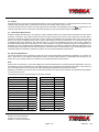
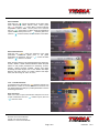
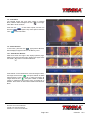
7.2.1 - Image Mode
Thermal Imager has 6 kinds of image modes for display. IR/Visible/IR_PIPE_VIS/
VIS_PIPE_IR/IR_Mix_VIS/VIS_Mix_IR.
IR: Displays only infrared image;
Visible: Displays only visible image;
IR_PIPE_VIS and VIS_PIPE_IR: Display infrared and visible image at the same
time;
IR_Mix_VIS and VIS_Mix_IR: Display fusion image of infrared and visible images.
In Image Menu, press the Icon ″ ″, shows the page of Image Mode. Press left
arrow or right arrow to change image mode.
In IR_PIPE_VIS and VIS_PIPE_IR mode, There are four options for image pipe
position: Topleft, Bottomleft, BottomRight, TopRight. ln ″Position:XX″ item, Press left
arrow or right arrow to change image pipe position.
Note:
TL: Topleft; BL:Bottomlef; BR:BottomRight; TR:TopRight.
In IR_Mix_VIS and VIS_Mix_IR mode, In ″Size: XX″ item, press left arrow or right
arrow to change image mix size. There are two options: Half or Full. In ″Blend:XX%″
item, press left arrow or right arrow to change image mix percentage. The range is
0% to 100%.

TM
TM
Page <15> V1.005/07/23
Newark.com/exclusive-brands
Farnell.com/exclusive-brands
Element14.com/exclusive-brands
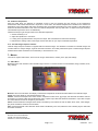
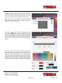
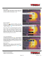
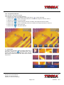
7.2.2 - Image Palette
The Image Palette lets you change the false-color presentation
of the infrared images on display or captured. A variety of
palettes are available for specic applications. Thermal Imager
has standard and custom palettes. The standard palettes
oer an equal, linear presentation of colours that allow for
best presentation of detail. The custom palettes allow user to
customize personal palettes.
In Image Menu, press the icon ″ ″, shows the page of Image
Palette. There are two groups of palette, Standard Palette
and Custom Palette. The * icon represents the current image
palette In the corresponding group.
Standard Palette
Press Standard bar, Popup the standard palette submenu.
It shows eight kinds of palettes, they are IRON, Rainbow, Grey,
Grey Inverted, Sepia, Blue_Red, Hot_Cold, Humidity. Press
“OK” button to select palette, press “Cancel” button to cancel.
Custom Palette
Press Custom bar, Popup the custom palette submenu.
It shows custom palettes. User can customize personalized
palette. There are at least two palettes, at most ten palettes.

TM
TM
Page <16> V1.005/07/23
Newark.com/exclusive-brands
Farnell.com/exclusive-brands
Element14.com/exclusive-brands
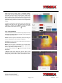
In custom palette submenu, there are ″Add″, ″Remove″,
″Rename″ functions. Long press for 1 second to show this
menu. ″Add″ is used to add a new palette; ″Remove″ is used
to remove a palette; ″Rename″ is used to rename palette.
Note: when there are only two palettes, ″Remove″ is disabled.
When there are ten palettes, ″Add″ is disabled. When palette
is selected, ″Rename″ is enabled.
Press the icon ″ ″, popup the menu for setting palette. There
is a colourbar to display current palette. The every colour value
is based on liner gradient ″0.0″ item displays the minimum
value, ″50.0″ displays the maximum value. There are 3 scales,
which the value is based on position, the minimum value and
maximum value. Press and move every scale can change the
position.
Press ″0.0″ or ″50.0″ to show menu for minimum or maximum
parameter settings. ″Min. Value″ shows the minimum value.
″Max. Value″ shows the maximum value. Click colour bar to
choose a colour, ″Current Colour″ shows current selected
colour. ″Red″, ″Green″ and ″Blue″ shows the colour value of
selected colour. Press the left arrow or right arrow can change
the corresponding value. Press ″OK″ button to save parameter
settings, Press ″Cancel″ button to cancel parameter settings.

TM
TM
Page <17> V1.005/07/23
Newark.com/exclusive-brands
Farnell.com/exclusive-brands
Element14.com/exclusive-brands
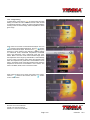
Press every scale to popup menu for parameter settings.
Click ″Enable″ to switch on(checked) or o (unchecked). Click
colour bar to choose a colour, ″Current Colour″ shows current
selected colour. ″Red″, ″Green″ and ″Blue″ shows the colour
value of selected colour. Press the left arrow or right arrow can
change the corresponding value. Press ″OK″ button to save
parameter settings, Press ″cancel″ button to cancel parameter
settings.
If ″Enable″ Is switched on (checked), It means to enable linear
gradient in this scale, the icon ″ ″ shows in the top of scale.
If ″Enable″ is switched o (unchecked), it means to disable
linear gradient in this scale, the icon ″ ″ will hide;
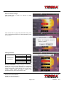
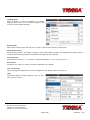
7.2.3 - Image Adjument
There are 3 kinds of modes for thermal image adjustment they
are All Auto, Histogram, Manual. Press left arrow or right arrow
to change image adjustment
All Auto: level and span are decided by the thermal image of
minimum temperature and maximum temperature.
Histogram: level and span are decided by the Histogram of
thermal image temperature.
Manual: level and span are decided by the manual values,
which decide by ″Max Temp″ and ″Min Temp″, Press the left
arrow or right arrow to change the value.
In image menu, press the icon ″ ″, shows the page of Image
Adjustment.
In Manual mode, press ″Adjust″ to open the menu for the
adjustment of level and span. Press left arrow or right arrow to
change value, press ″Level″ to ″Span″, press ″Span″ to ″Level″.

TM
TM
Page <18> V1.005/07/23
Newark.com/exclusive-brands
Farnell.com/exclusive-brands
Element14.com/exclusive-brands
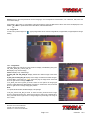
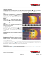
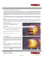
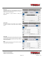
7.2.4 - Image Setting
In Image Menu, press the icon ″ ″ is how the page of Image
Setting. It contains the ″ISO″ and “Clear Screen. ″ISO″ is used
for isothermal analysis. It allows to Thermal Imagers displays
a setting colour for Infrared Image, which temperature is in the
given range.
Press ″ISO″ bar to switch on/o isothermal analysis. The Icon
″ ″ means to open isothermal analysis; the Icon ″ ″ means
to close isothermal analysis. Press the icon ″ ″ popup the
submenu of ″ISO″ settings. This submenu contains settings
for Isothermal mode, Isothermal temperature, Isothermal
range and Isothermal colour. Isothermal mode has Inter,
Above, Below. The Inter mode means infrared image which
the temperature in the range of [Level-Width/2, Level+Width/2]
is set to Colour; The Above mode means the infrared image
which the temperature is greater than Level+Width/2 is set to
Colour; The Below mode means the infrared image which the
temperature is less than Level-Width/2 is set to Colour. The
Colour has Black, White, Green and Red to select.
Press ″Clear Screen″ bar to show only image in the screen.
The Icon ″ ″ means to clear screen, The Icon ″ ″ means
to don’t clear screen.

TM
TM
Page <19> V1.005/07/23
Newark.com/exclusive-brands
Farnell.com/exclusive-brands
Element14.com/exclusive-brands
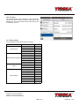
7.2.5 - Zoom and Rotation
Thermal Imager oers 1-20x continuous zoom and 0°- 360° rotation functions. Press the icon ″ ″ which in top-left of the
display, popup the menu of Zoom and Rotation. In the menu of Zoom and Rotation, press the icon, ″ ″ Image restores to
its original state, without zoom and rotation. Press the icon ″OK″ or Push HOME ″ ″ button, exit current menu.
Zoom
Press the icon ″ ″, image zoom out 10%, long press will
continue to zoom out. Press the icon, ″ ″ image zoom in
10%, long press will continue to zoom In. When zoom In or
zoom out, the zoom factor displays in the upper-right comer
of the display.
Rotation
Press the icon ″ ″ , image counterclockwise rotates 1°,
long press will continue to rotate and accelerate the speed of
rotation.
Press the icon ″ ″ , image counterclockwise rotates 1°,
long press will continue to rotate and accelerate the speed of
rotation.
When rotated an angle, the angle of rotation displays in the
upper-right corner of the display.
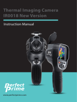
7.3 - Measurement Menu
In main menu, press measurement icon ″ ″, popup
Measurement Menu which contains Point Measurement.
Line Measurement. Area Measurement and Measurement
Settings.
Point Measurement: Measure the selected points, each
point can move, capture maximum temperature and minimum
temperature.
Line Measurement: Use temperature curve to display the
prole for measured target
Area Measurement: Measure the selected area, contains
maximum temperature, minimum temperature and average
temperature.
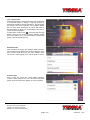
7.3.1 - Point Measurement
In measurement menu, press the icon ″ ″ ,shows the page of Point Measurement. There are 3 points to measure. Each point
has third kinds of mode: manual mode, maximum temperature capture, minimum temperature capture. Each point can use
global parameter settings or global parameters to set the measuring parameters.
Open and Close
Press Spot 1, Spot 2, Spot 3 to open the corresponding point of the temperature measurement. The Icon ″ ″ means to open
point measurement, The Icon ″ ″ means to close point measurement.

TM
TM
Page <20> V1.005/07/23
Newark.com/exclusive-brands
Farnell.com/exclusive-brands
Element14.com/exclusive-brands
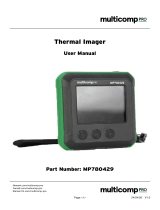
Set Point Mode
Press the icon ″ ″ popup the submenu of the point mode.
Press ″Manual″ to select manual mode, current points
icon ″ ″ becomes ″ ″ Press ″Max″ to select maximum
temperature capture mode, current point’s icon becomes
red icon ″ ″; Press ″Min″ to select maximum temperature
capture mode, current point’s icon ″ ″ become green icon;
The Icon ″ ″ means to select, The Icon means to not select.
Set Point Parameters
Press the icon ″ ″, popup the submenu of the point
parameters. Press ″use global para″ to use global
parameters for measuring. The Icon ″ ″ means to select
The Icon ″ ″ means to not select.
When the point selects to use global parameters for measuring,
″Emiss″, ″Distan″, ″Oset″ becomes disabled. When the point
selects to use private parameters for measuring, ″Emiss″,
″Distan″, ″Oset″ becomes enabled. ″Emiss″ sets object
emissivity, the value range is 0.01 to 1.00; ″Distan″ sets object
distance, the value range is 0 to 5000; ″Oset″ sets object
oset, the value range is -100°C to 100°C;
7.3.2 - Line Measurement
In measure menu, press the icon ″ ″,show the page of Line
Measurement. There are 2 lines to measure. Each line can
use global parameter settings or private parameters to set the
measuring parameters.
Open and Close
Press ″Hor Line″ to open horizontal line and press ″Ver Line″
to open vertical line. The Icon ″ ″ means to open, The Icon
″ ″ means to close.
Page is loading ...
Page is loading ...
Page is loading ...
Page is loading ...
Page is loading ...
Page is loading ...
Page is loading ...
Page is loading ...
Page is loading ...
Page is loading ...
Page is loading ...
Page is loading ...
Page is loading ...
-
 1
1
-
 2
2
-
 3
3
-
 4
4
-
 5
5
-
 6
6
-
 7
7
-
 8
8
-
 9
9
-
 10
10
-
 11
11
-
 12
12
-
 13
13
-
 14
14
-
 15
15
-
 16
16
-
 17
17
-
 18
18
-
 19
19
-
 20
20
-
 21
21
-
 22
22
-
 23
23
-
 24
24
-
 25
25
-
 26
26
-
 27
27
-
 28
28
-
 29
29
-
 30
30
-
 31
31
-
 32
32
-
 33
33


Ask a question and I''ll find the answer in the document
Finding information in a document is now easier with AI
Other documents
-
 PerfectPrime IR0018 User manual
-
 multicomp pro MP780429 Operating instructions
-
Intellisystem TT-607FG-HTI User manual
-
 multicomp pro MP780833 Operating instructions
-
Fluke Ti480U Ti401U Ti300U Infrared Thermal Cameras User manual
-
 multicomp pro MP780834 Operating instructions
-
Futech Tempviewer 6400 Owner's manual
-
REED R2050 User manual
-
 PerfectPrime IR0019 User manual
-
Yellow Jacket 65273340 User guide


