nilan MB64 VPM 600-3200 User manual
- Category
- Split-system air conditioners
- Type
- User manual

INSTALLATION & SERVICE INSTRUCTIONS
CTS602i HMI BY NILAN
Version 3.10- 19.01.2024
MB64_VPM_600-3200_ GB
VPM 600-3200

2
Table of contents
Safety
Power supply ...................................................................................................................................................................................................4
Pressure-bearing equipment ....................................................................................................................................................................... 4
Disposal .................................................................................................................................................................................................................. 4
Heat pump ........................................................................................................................................................................................................ 4
General information
Introduction........................................................................................................................................................................................................... 5
General information prior to installation ...................................................................................................................................................5
Disclaimer......................................................................................................................................................................................................... 5
Symbols explained .......................................................................................................................................................................................... 5
Application of instruction manual ............................................................................................................................................................... 5
Data plate ......................................................................................................................................................................................................... 6
Warnings and regulations ................................................................................................................................................................................... 6
Inappropriate use ........................................................................................................................................................................................... 6
No duct connection ......................................................................................................................................................................................... 6
Opening the unit .............................................................................................................................................................................................. 6
Unit in standby mode ..................................................................................................................................................................................... 6
Unit type ................................................................................................................................................................................................................ 7
Product description ........................................................................................................................................................................................ 7
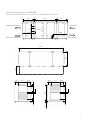
Dimensional drawing for VPM 600 .............................................................................................................................................................. 9
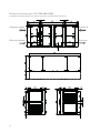
Dimensional drawing for VPM 700-800-1000 ........................................................................................................................................10
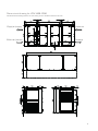
Dimensional drawing for VPM 1200-1500 ..............................................................................................................................................11
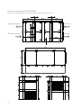
Dimensional drawing for VPM 2200 ..........................................................................................................................................................12
Dimensional drawing for VPM 3200 ..........................................................................................................................................................13
Placing of vibration absorbers ...................................................................................................................................................................14
Functional diagram VPM 600-3200 ..........................................................................................................................................................15
Accessories .........................................................................................................................................................................................................16
CO2-sensor ..................................................................................................................................................................................................... 16
Electrical after-heating element - integral ..............................................................................................................................................16
Pressure-controlled filter alarm ................................................................................................................................................................ 16
Humidity sensor ............................................................................................................................................................................................ 16
Handle with cylinder lock ............................................................................................................................................................................16
Pressure control ...........................................................................................................................................................................................16
Water after-heating element - integral ....................................................................................................................................................16
Water trap with ball ......................................................................................................................................................................................17
Heating cable .................................................................................................................................................................................................17
Internal heating cable inside the condensate drain................................................................................................................................17
Vibration absorbers .....................................................................................................................................................................................17
Variable compressor ....................................................................................................................................................................................17
Installation
Handling ...............................................................................................................................................................................................................18
Unwrapping ....................................................................................................................................................................................................18
Transport after unwrapping .......................................................................................................................................................................18
Installation ........................................................................................................................................................................................................... 19
Positioning the unit .......................................................................................................................................................................................19
Positioning and installation of unit ............................................................................................................................................................20
Outdoor installation .....................................................................................................................................................................................24

3
Electrical installation
Electrical connections .......................................................................................................................................................................................25
Safety .............................................................................................................................................................................................................25
Connection overview ...................................................................................................................................................................................25
Power supply .................................................................................................................................................................................................26
Unit ..................................................................................................................................................................................................................26
Control panel ....................................................................................................................................................................................................... 27
CTS602i HMI Touch ....................................................................................................................................................................................... 27
Wall bracket ...................................................................................................................................................................................................27
Electrical connection accessories ...................................................................................................................................................................28
Electrical after-heating element ...............................................................................................................................................................28
Water after-heating element .....................................................................................................................................................................29
Plumbing installation
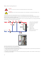
Condensate drain ...............................................................................................................................................................................................30
Important information ................................................................................................................................................................................. 30
Connection of water trap ............................................................................................................................................................................30
Plumbing connections - accessories ............................................................................................................................................................... 31
Connection of water trap with ball ............................................................................................................................................................31
Water after-heating element .....................................................................................................................................................................32
Performance data for integral water after-heating elements ............................................................................................................33
Ventilation installation
Duct system ........................................................................................................................................................................................................36
Legislation ...................................................................................................................................................................................................... 36
Duct connections ..........................................................................................................................................................................................36
Balancing .............................................................................................................................................................................................................36
Important information ................................................................................................................................................................................. 36
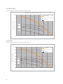
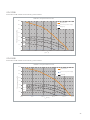
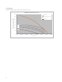
Performance curves for SEL value assessment ........................................................................................................................................... 37
VPM 600 .........................................................................................................................................................................................................37
VPM 700 .........................................................................................................................................................................................................37
VPM 800-1000 ..............................................................................................................................................................................................38
VPM 1200 ....................................................................................................................................................................................................... 38
VPM 1500 ....................................................................................................................................................................................................... 39
VPM 2200 ....................................................................................................................................................................................................... 39
VPM 3200 ....................................................................................................................................................................................................... 40
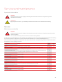
Service and maintenance
Important information ................................................................................................................................................................................. 41
Service .................................................................................................................................................................................................................41
Maintenance schedule .................................................................................................................................................................................41
Filter replacement .......................................................................................................................................................................................42
Cleaning ...............................................................................................................................................................................................................42
Cleaning the unit ...........................................................................................................................................................................................42
Ordering spare parts
Filters VPM 600 ............................................................................................................................................................................................. 43
Filters VPM 700-800-1000 .........................................................................................................................................................................43
Filters VPM 1200-1500 ...............................................................................................................................................................................43
Filters VPM 2200 ..........................................................................................................................................................................................43
Filters VPM 3200 ..........................................................................................................................................................................................43

4
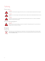
Safety
Power supply
Pressure-bearing equipment
Disposal
Heat pump
Power supply
CAUTION
Always disconnect the power supply to the unit if an error occurs that cannot be rectifi ed via the control panel.
CAUTION
If an error occurs on electrically conductive parts of the unit, always contact an authorised electrician to rectify
the error.
CAUTION
Always disconnect the power to supply to the unit before opening the unit doors, for instance for installation,
inspection, cleaning and fi lter change.
Pressure-bearing equipment
WARNING
Exercise great caution when handling cooling circuit components. They have a pressure of up to 50 bar and, if
damaged, they can cause personal injury.
Heat pump
When disposing of units with heat pumps, it is important to contact the local authorities for information about
the correct disposal procedure. The heat pumps contain the refrigerant R134a, which is harmful to the environ-
ment if not handled correctly.

5
General information
Introduction
General information prior to installation
Disclaimer
Symbols explained
Application of instruction manual
General information prior to installation
The following documents will be supplied with the unit:
•
Installation and service instructions
•
Software instructions
•
Wiring diagram
The instructions can be downloaded from:
www.nilan.dk.
If you have questions regarding installation and operation of the unit after having read the instructions, please contact your
nearest Nilan dealer. A list of Nilan dealers is available on:
www.nilan.dk
ATTENTION
In order to avoid discolouration of the metal sheets, remove the protective foil packaging from the unit immedi-
ately after delivery. Discolouration is caused by a chemical reaction triggered by condensation between the foil
and the galvanized sheets. Then, if necessary, cover the unit with tarpaulin to protect it.
The unit is delivered from the factory, tested and ready for operation.
Disclaimer
In order to achieve correct operation of the unit and to ensure the safety of persons and equipment, the instructions must be
followed. Nilan A/S disclaims all responsibility for damages resulting from usage of the unit and/or accessories confl icting with
the directions and instructions of this manual.
Symbols explained
WARNING
Violation of instructions marked with a warning symbol could be hazardous to life.
ATTENTION
Violation of instructions marked ATTENTION could pose risk of personal injury or damage to equipment.
Application of instruction manual
This instruction manual applies to Nilan’s ventilation and heat recovery unit, hereafter referred to as unit. Information on
accessories that are included and other additional equipment can be found in the Accessories section.

6
Data plate
Warnings and regulations
Inappropriate use
No duct connection
Opening the unit
Unit in standby mode
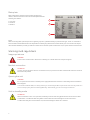
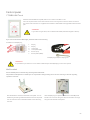
Data plate
Nilan’s data plate is located on the inside of the electrical
cabinet, which is mounted on the unit. The data plate holds the
following information:
1.
Unit type
2.
Order no.
3.
Serial no.
Note!
When contacting Nilan A/S with questions regarding a product, please be ready to quote the unit type, order no. and serial no.
This information will enable the service department to identify any relevant information about your unit. The service depart-
ment will then be able to provide you with information and to answer questions about the unit, its parts and the software used.
1
2
3
Inappropriate use
WARNING
The unit must not be used for extraction of shavings or in areas with a risk of explosive gases.
No duct connection
ATTENTION
If one or more of the spouts are not connected to a duct, a protective net with a mesh width of max 20 mm must
be fi tted on this/these.
Opening the unit
WARNING
Do not open the service doors until the power supply has been disconnected on the safety switch and the fans
have stopped.
In accordance with EN 1886, for safety reasons you should only be able to open the service doors by means of a
tool. For this purpose, please use the supplied “key”. Alternatively, you can use a large screwdriver.
Unit in standby mode
ATTENTION
When a ventilation unit is not in operation, humidity from the rooms may penetrate into the ducts and create
condensation. Condensate water may leak from the valves and cause damage to furniture and fl oors.
Condensation may also form inside the unit, which can damage its electronics and fans.

7
Unit type
Product description
Unit type
Product description
The VPM 600-3200 series is a ventilation and heat recovery unit with cooling and heating functions developed especially for
commercial constructions with an air exchange requirement of up to 32,000 m3 per hour.
A VPM unit removes the “used”, humid air from the building and supplies new, “fresh” air in turn. The energy in the extract air is
recovered and transferred to the supply air via a unique combination of active (heat pump) and passive (heat pipe) heat recovery.
The high effi ciency of the VPM series is due to this unique design, which combines the best of two technologies. This improves
effi ciency so much that it comes close to 100 %. This means that the need for heat supply during the cold winter months is reduced
to a minimum, and signifi cant savings are achieved on the building’s energy consumption and a reduction in CO
2 emissions. During
summer the process is reversed and the supply air is cooled.
It is possible to add a heat exchanger to the refrigeration circuit. It enables utilisation of excess energy or waste energy created
by the cooling process, for example, for heating domestic hot water.
The unit is modularly designed according to individual wishes and needs, making it an extremely easy-to-install plug-and-play
solution. The unit can be controlled and monitored via our CTS602i control system.
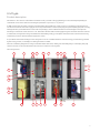
Left-facing version:
7
2
13a
3
6
16
12 15a 8
21
4
1
18 5
15b14
11
20
17
9
13b
19 19 19 19
10
20

8
1. Outdoor air duct connection
2. Duct connection supply air
3. Duct connection extract air
4. Duct connection discharge air
5. Outdoor air fi lter
6. Extract air fi lter
7. Supply air fan
8. Extract air fan
9. Electrical connections
10. Connection of HMI control panel
11. Automation (inside the electrical cabinet)
12. Valves for refrigerant manometer
13. Pipe for fl ow/return to water after-heating element (see picture14)
a. fl ow
b. return
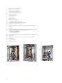
14. After-heating element water/electricity (accessory - see picture 14)
15. Condensers and evaporators (see picture 15)
a. Evaporator/Condenser
b. Condenser/Evaporator
16. Heat pipe / passive heat exchanger (behind the screen - see picture 16)
17. Compressor
18. Frequency converter for compressor (only by VTZ compressor)
19. Lifting eyes
20. Shut-off damper
21. Condensate drain
14. 15. 16.

9
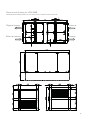
Dimensional drawing for VPM 600
The dimensioned drawing below is for a left-facing version. All measurements are in mm.
3910
1370
750
800285 285
1480
80 ± 15
180 600 600
85
75
285 285
800
75
600600
85
180
950 950
5 5
2000
140330
1050
600
1225
50
Tilluft (indblæsning)
Fraluft (udsugning)
Udeluft
Afkastluft
Supply air (supply)
Extract air (extract) Discharge
Outdoor air

10
Dimensional drawing for VPM 700-800-1000
The dimensioned drawing below is for a left-facing version. All measurements are in mm.
Tilluft (indblæsning)
Fraluft (udsugning)
Udeluft
Afkastluft
Supply air (supply)
Extract air (extract) Discharge
Outdoor air

11
Dimensional drawing for VPM 1200-1500
The dimensioned drawing below is for a left-facing version. All measurements are in mm.
Tilluft (indblæsning)
Fraluft (udsugning)
Udeluft
Afkastluft
Supply air (supply)
Extract air (extract) Discharge
Outdoor air

12
Dimensional drawing for VPM 2200
The dimensioned drawing below is for a left-facing version. All measurements are in mm.
Tilluft (indblæsning)
Fraluft (udsugning)
Udeluft
Afkastluft
Supply air (supply)
Extract air (extract) Discharge
Outdoor air

13
Dimensional drawing for VPM 3200
The dimensioned drawing below is for a left-facing version. All measurements are in mm.
Tilluft (indblæsning)
Fraluft (udsugning)
Udeluft
Afkastluft
Supply air (supply)
Extract air (extract) Discharge
Outdoor air

14
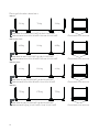
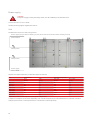
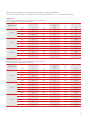
Placing of vibration absorbers
VPM 600
VPM 700-800-1000
VPM 1200-1500
VPM 2200
310kg 720kg 310kg
Med fundament: 8 brun 100x100x25 + 4 rød 100x100x25
Uden fundament: 4 rød 100x100x25 + 8 brun 100x100x25 Placeres både front og bag
425kg 900kg 425kg
Med fundament: 4 rød 100x100x25 + 4 grå 100x100x25
Uden fundament: 4 rød 100x100x25 + 8 brun 100x100x25 Placeres både front og bag
600kg 1200kg 600kg
Med fundament: 4 grå 120x120x25 + 4 rød 120x120x25
Uden fundament: 4 rød 120x120x25 + 8 rød 100x100x25 Placeres både front og bag
750kg 1750kg 750kg
Med fundament: 4 grå 120x120x25 + 4 rød 120x120x25
Uden fundament: 4 grå 100x100x25 + 8 rød 100x100x25 Placeres både front og bag
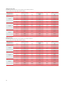
VPM 3200
Functional diagram VPM 600-3200
910kg 2150kg 910kg
Med fundament: 4 grå 120x120x25 + 4 rød 120x120x25
Uden fundament: 4 grå 100x100x25 + 8 rød 100x100x25 Placeres både front og bag
Placed both front and rear
Placed both front and rear
Placed both front and rear
Placed both front and rear
With base: 8 brown 100x100x25 + 4 red 100x100x25
Without base: 4 red 100x100x25 + 8 brown 100x100x25
With base: 4 red 100x100x25 + 4 grey 100x100x25
Without base: 4 red 100x100x25 + 8 brown 100x100x25
With base: 4 grey 120x120x25 + 4 red 120x120x25
Without base: 4 red 120x120x25 + 8 red 100x100x25
With base: 4 grey 120x120x25 + 4 red 120x120x25
Without base: 4 grey 100x100x25 + 8 red 100x100x25
With base: 4 grey 120x120x25 + 4 red 120x120x25
Without base: 4 grey 100x100x25 + 8 red 100x100x25 Placed both front and rear

15
VPM 3200
Functional diagram VPM 600-3200
910kg 2150kg 910kg
Med fundament: 4 grå 120x120x25 + 4 rød 120x120x25
Uden fundament: 4 grå 100x100x25 + 8 rød 100x100x25 Placeres både front og bag
Placed both front and rear
Placed both front and rear
Placed both front and rear
Placed both front and rear
With base: 8 brown 100x100x25 + 4 red 100x100x25
Without base: 4 red 100x100x25 + 8 brown 100x100x25
With base: 4 red 100x100x25 + 4 grey 100x100x25
Without base: 4 red 100x100x25 + 8 brown 100x100x25
With base: 4 grey 120x120x25 + 4 red 120x120x25
Without base: 4 red 120x120x25 + 8 red 100x100x25
With base: 4 grey 120x120x25 + 4 red 120x120x25
Without base: 4 grey 100x100x25 + 8 red 100x100x25
With base: 4 grey 120x120x25 + 4 red 120x120x25
Without base: 4 grey 100x100x25 + 8 red 100x100x25 Placed both front and rear
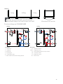
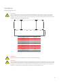
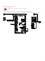
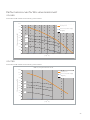
Functional diagram VPM 600-3200
Connections Automation
1: Outdoor air T1: Outdoor air sensor
2: Supply air T2/T7: Supply air sensor
3: Extract air T9: After-heating element frost protection
4: Discharge air T5: Condenser sensor
5: Condensation drain T6: Evaporator sensor
6: Electrical and water after-heating element T10: Room sensor
T5
T10
T6
2
4
6
5
TC
TC
T1
1
3
T2
2
T5
T9
T6
4
6
5
TC
TC
T1
1
3
T2/T7
T10
TC
Heating Cooling

16
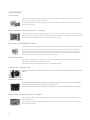
Accessories
CO2-sensor
Electrical after-heating element - integral
Pressure-controlled filter alarm
Humidity sensor
Handle with cylinder lock
Pressure control
Water after-heating element - integral
CO2-sensor
If you want the ventilation level to regulate in accordance with how many people are in the building, you
can order a unit with an integral CO2-sensor.
On the control panel you set the CO2-level you want. If this level is exceeded, ventilation will increase to
the set fan speed level.
Electrical after-heating element - integral
You will need to order an after-heating element if, for instance, you want to use the ventilation unit for
heating the building. The electrical after-heating element is installed in the ventilation unit at the factory.
The electrical after-heating element requires its own power supply.
Pressure-controlled fi lter alarm
As standard, the control system has a time-controlled fi lter alarm that can be set between 30 and 360 days.
If you want an accurate indication of when to change the fi lter, we recommend that you order a pres-
sure-controlled fi lter alarm. It displays the pressure drop over the fi lters in the CTS control system
regularly. You pre-set a fi nal pressure drop in the control system, and an alarm will indicate when this
pressure drop has been reached and the fi lters need replacing.
Humidity sensor
If you want to regulate the fan speed level in accordance with the humidity level in the extract air, you
can order a unit with an integral humidity sensor.
The unit can change the fan speed level to low or high humidity level.
Handle with cylinder lock
If you want to be able to lock the service doors to the unit, you can purchase handles with a cylinder lock
and key.
Pressure control
The motor for the extract and/or supply air fan can be controlled by one or two pressure transmitters.
These should be mounted in the extract and/or supply air duct.
The standard version is delivered with pressure transmitters and a 5 m cable, including power supply.
Water after-heating element - integral
You will need to order an after-heating element if, for instance, you want to use the ventilation unit for
heating the building.
The water after-heating element is installed in the unit at the factory and it comes with a 3-way valve
and a Danfoss Actuator.

17
Water trap with ball
Heating cable
Internal heating cable inside the condensate drain
Vibration absorbers
Variable compressor
Water trap with ball
Ensures that condensate water can drain freely - also from compartments in the unit with negative
pressure. Should the water trap dry out, the ball will prevent air from being drawn into the system, and
condensate water will drain away freely.
Heating cable
If you install the ventilation unit outside the climate screen, it is important to protect the condensate
drain from frost.
Nilan A/S can supply an external heating cable that you run along the exterior of the condensate drain
before insulating it. This way you will have a frost free condensate drain that does not get blocked. The
heating cable has an integral thermostat that regulates the level of heating in accordance with the tem-
perature of the surroundings.
The cable is available in two lengths: 3 m or 5 m.
Internal heating cable inside the condensate drain
Internal heating cable for frost protection of the condensate drain running from the condensate tray
inside the unit to the water trap outside the unit.
Vibration absorbers
Vibration absorbers ensure that vibrations from the unit to the underlying surface are dampened
effectively. The vibration absorbers are placed under the unit.
Variable compressor
As standard, the ventilation unit is delivered with an on/off compressor.
The unit is also available with a variable compressor, which enables much better regulation of operation.
This means much lower energy consumption too.

18
Installation
Handling
Unwrapping
Transport after unwrapping
Unwrapping
The unit is delivered wrapped in foil. In order to protect the galvanized sheets on the unit from discolouration, immediately
remove the foil. You may consider covering the unit with tarpaulin until installation.
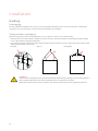
Transport after unwrapping
When you are going to position and install the unit, you can transport or move it in two different ways:
•
Lifting the unit from underneath with a pallet truck. Units with a pre-mounted foundation can be lifted directly with a pallet
truck - take care NOT to damage the base feet.
•
If you are lifting the unit using ropes/straps, the base angles must be more than 60°.If this is impossible due to a lack of space,
a lifting beam or similar must be used.
Lifting eye Min. 60 ° Lifting beam
ATTENTION
Visible transport damages must be reported immediately. Hidden transport damages must be reported within 7
days of delivery. When reporting transport damages, photo documentation is required.
Please see Incoterms 2020 for terms of delivery, warranties, limitation periods and compensation limits etc.

19
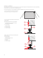
Installation
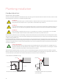
Positioning the unit
Positioning the unit
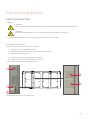
ATTENTION
Good clearance in front of the unit is recommended (see table below). When positioning the unit, you should
always consider future service and maintenance. It must be easy to replace fi lters and it must be possible to
replace fans or other components. There must be enough space to clean the unit easily. There must be space for
installing water traps in the condensate drains.
ATTENTION
The unit must be level to enable proper drainage from the condensate tray.
ATTENTION
The unit makes little noise and it produces only weak vibrations, but you should still take into account potential
vibrations that can spread from the unit to individual building components. In order to separate the unit from its
underlying surface, it is therefore recommended that you fi t vibration absorbers under the unit. There should
be approx. 10 mm distance to other building components and to permanent fi xtures.
X
Unit X (in mm)
VPM 600 750
VPM 700 750
VPM 800 750
VPM 1000 750
VPM 1200 800
VPM 1500 800
VPM 2200 950
VPM 3200 1050

20
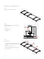
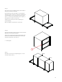
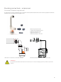
Positioning and installation of unit
Positioning and installation of unit
Step 1
Foundation is placed in the desired place.
Step 2
The vibration dampers (sylomes) are placed under
the adjusting screws.
a. Nilan base
b. Adjusting screws
c. Sylomes
66
126
80
180±20
8
25
35-75
a
b
c
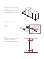
Step 3
Base is adjusted.
a. This section is for the discharge module and thus
is not present where this is not included in the
delivery.
b. Ensure that the base is level.
c. Make a cross measurement so that the founda-
tion is at an angle.
a
b
c
Page is loading ...
Page is loading ...
Page is loading ...
Page is loading ...
Page is loading ...
Page is loading ...
Page is loading ...
Page is loading ...
Page is loading ...
Page is loading ...
Page is loading ...
Page is loading ...
Page is loading ...
Page is loading ...
Page is loading ...
Page is loading ...
Page is loading ...
Page is loading ...
Page is loading ...
Page is loading ...
Page is loading ...
Page is loading ...
Page is loading ...
Page is loading ...
-
 1
1
-
 2
2
-
 3
3
-
 4
4
-
 5
5
-
 6
6
-
 7
7
-
 8
8
-
 9
9
-
 10
10
-
 11
11
-
 12
12
-
 13
13
-
 14
14
-
 15
15
-
 16
16
-
 17
17
-
 18
18
-
 19
19
-
 20
20
-
 21
21
-
 22
22
-
 23
23
-
 24
24
-
 25
25
-
 26
26
-
 27
27
-
 28
28
-
 29
29
-
 30
30
-
 31
31
-
 32
32
-
 33
33
-
 34
34
-
 35
35
-
 36
36
-
 37
37
-
 38
38
-
 39
39
-
 40
40
-
 41
41
-
 42
42
-
 43
43
-
 44
44


nilan MB64 VPM 600-3200 User manual
- Category
- Split-system air conditioners
- Type
- User manual
Ask a question and I''ll find the answer in the document
Finding information in a document is now easier with AI
Related papers
Other documents
-
CELL-DYN 3200 User manual
-
Siemens 6SN1123-1AA00-0LA1 Configuration manual
-
 Kaiser Fototechnik 4000 Datasheet
-
Broadcom BCM21553 GPU Documentation User guide
-
Premier Mounts MM-VH423 Specification
-
H3C MSR 5680 Replacement Procedures
-
Datalogic P1x-Series Product Reference Guide
-
Schmalz SMP 20 NO AS VD Operating instructions
-
Rosemount CCO 5500 Carbon Monoxide (CO) Analyzer-Rev 1.0 Owner's manual
-
