Page is loading ...

This product functions with TRIAC technology
to intelligently adjust the brightness level of
incandescent and hallogen lights. If programmed,
it can be utilized for integrating ceiling fans into
home automation system.
Model: DIM-4CH-3A
6 58921 79831 7
BARCODE (UPC-A)
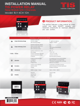
PRODUCT INFORMATION
INSTALLATION MANUAL
TIS LEADING EDGE DIMMER
Dimmer controller with four channels
PRODUCT SPECIFICATIONS
I/O Load Voltage
Number of channels 4
Nominal voltage 110/230 V AC 50/60 Hz
Nominal current per channel 3 A
Maximum total channel load 10 A
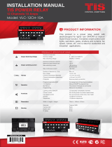
TIS Bus
Number of devices on 1 line Max. 64
Bus voltage 12-32 V DC
Current consumption <30 mA / 24 V DC
Protection Reverse polarity protection
Protection
Over current 4x internal fuse aR class 6A
Over heat Internal temp sensor protection
Over load Dimmer coil max load up to 6A
Heat sink Aluminum alloy with straight fin
Operation
Programming button/LED For assignment of the physical address
1-4 buttons Manual ON/OFF and programming
By TIS-BUS TIS protocol messages and commands
Programming Manual & via software
Upgrading 1 X mini USB for upgrading
Functions
Lighting control dimming 4 separately controllable channels
Scenes 8 different scenarios
Sequences 6 different sequences
Dimensions Width × Length × Height 144mm × 76mm × 90mm
Housing
Materials Fireproof ABS
Casing color Black
Button color Silver
IP rating IP 20

2
www.tiscontrol.com
TIS CONTROL LIMITED
Wanchai, Hong Kong
TIS CONTROL PTY LIMITED
SA , AUSTRALIA
Copyright © 2022 TIS, All Rights Reserved
TIS Logo is registered trademark of TIS CONTROL.
All of the specification are subject to change without notice.
INSTALLATION MANUAL
MODEL: DIM-4CH-3A
TIS LEADING EDGE DIMMER
Data Cable
Use screened stranded RS485 data cable
with four twisted pairs. Congure devices in
a “Daisy Chain.”
Do not cut or terminate live data cables.
Electrical Wires
The recommended wire size for light
channels is 2.5mm, and 4mm for the
Line, Neutral, and Earth cables. The
installer should consider the total current
consumption when selecting the wires.
Warranty
There is a two-year warranty provided
by law. The hologram warranty seal and
product serial number are available on
each device.
Read Instructions
We recommend that you read this
Instruction Manual before installation.
Safety instructions
Electrical equipment should only be
installed and tted by electrically skilled
persons.
Failure to observe the instructions may
cause damage to the device and other
hazards.
These instructions are an integral part of
the product and must remain with the end
customer.
Programming
This device can be tested and programmed
manually. Advanced programming
requires knowledge of the TIS Device
Search software and instruction in the TIS
advanced training courses.
Simple Installation
You can use either the DIN rail or xing
points to install this module.
Mounting Location
Install in a dry, well-ventilated location.
Controllers may emit some mechanical
noises. Consider this when deciding on a
mounting location.

3
www.tiscontrol.com
TIS CONTROL LIMITED
Wanchai, Hong Kong
TIS CONTROL PTY LIMITED
SA , AUSTRALIA
Copyright © 2022 TIS, All Rights Reserved
TIS Logo is registered trademark of TIS CONTROL.
All of the specification are subject to change without notice.
INSTALLATION MANUAL
MODEL: DIM-4CH-3A
TIS LEADING EDGE DIMMER
Turn off the main electrical source before
installation.
1WARNING! HIGH VOLTAGE
Mount the device on DIN Rails inside an
approved enclosure. The device can also
be installed using two mounting screw
holes.
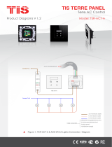
2
+24D+D-GND+24D+D-GND
Connect a Cat5e TIS network data
cable to the TIS-BUS port as per the
connection diagram. No need to loop the
TIS-bus cable if 2 DIN Rail modules are
connected together from the side bus
train terminal.
3
DIM-4CH-3A
TIS-BUS
GND D- D+ +24V
PRG
1 2 3 4
LOAD
2341N L
N
GND(white-orange)&(white-brown)
D-(white-green)&(white-blue)
D+(blue-green)
+24V(brown-orange)
Cat5e connection
To the TIS BUS Network
Cat5e
Connect the load (light channel) electrical
wires to outputs 1-4. The device is
capable of managing up to 10 Amps, and
each channel dims up to 3A loads. The
installer should make sure not to overload
the device and module channels.
4
1.5 mm Electric Cable
1.5 mm Electric Cable
GND(white-orange)&(white-brown)
D-(white-green)&(white-blue)
D+(blue-green)
+24V(brown-orange)
Cat5e connection
DIM-4CH-3A
TIS-BUS
GND D- D+ +24V
PRG
1 2 3 4
LOAD
2341N L
N
To the TIS BUS Network
Cat5e
INSTALLATION STEPS

4
www.tiscontrol.com
TIS CONTROL LIMITED
Wanchai, Hong Kong
TIS CONTROL PTY LIMITED
SA , AUSTRALIA
Copyright © 2022 TIS, All Rights Reserved
TIS Logo is registered trademark of TIS CONTROL.
All of the specification are subject to change without notice.
INSTALLATION MANUAL
MODEL: DIM-4CH-3A
TIS LEADING EDGE DIMMER
Connect the L, N, and PE to Live, Neutral,
and Earth cables, respectively. The
device input must have an appropriate
MCB to protect that load circuit.
5
Turn on the power source, and then
test the loads by short pressing on local
override buttons 1-4 on the device.
6
O-OFF
I-ON
MCB
Connect To L
Connect To Earth
Connect To N
1.5 mm Electric Cable
1.5 mm Electric Cable
2.5 mm Electric Cable
GND(white-orange)&(white-brown)
D-(white-green)&(white-blue)
D+(blue-green)
+24V(brown-orange)
Cat5e connection
1.5 mm Electric Cable
DIM-4CH-3A
TIS-BUS
GND D- D+ +24V
PRG
1 2 3 4
LOAD
2341N L
N
To the TIS BUS Network
Cat5e
DIM-4CH-3A
TIS-BUS
GND D- D+ +24V
PRG
1 2 3 4
LOAD
2341N L
N
GND(white-orange)&(white-brown)
D-(white-green)&(white-blue)
D+(blue-green)
+24V(brown-orange)
Cat5e connection
To the TIS BUS Network
Cat5e
INSTALLATION STEPS

5
www.tiscontrol.com
TIS CONTROL LIMITED
Wanchai, Hong Kong
TIS CONTROL PTY LIMITED
SA , AUSTRALIA
Copyright © 2022 TIS, All Rights Reserved
TIS Logo is registered trademark of TIS CONTROL.
All of the specification are subject to change without notice.
INSTALLATION MANUAL
MODEL: DIM-4CH-3A
TIS LEADING EDGE DIMMER
You can pair the light channels with any wall panels. To do so, follow these
steps:
Shortly press the light icons on any wall
panel, such as Luna, Mars, Terre, etc.
2
TER-4G
45mm
25mm
TER-4G
D-
24V GND
D+
45mm
221
227A
12EM4
227A
12EM4
TER-4G-A
45mm
25mm45mm
TER-4G-A
ADD-3R-5A
ADD-3R-5A
50mm
24mm54mm
PANEL ADDITION
3 Output Relay 5 Amp
Model : ADD-3R-5A
TIS BUS Input : 45-75mA/24V DC
Output Current : 3A220VAC
COM OUT3 OUT2 OUT1 COM
www.tissmarthome.com
D- +24V
GND D+
Press on any buttons 1-4 for 6 seconds
so that the LED indicator of that button
starts blinking.
1
DIM-4CH-3A
TIS-BUS
GND D- D+ +24V
PRG
1 2 3 4
LOAD
2341N L
N
GND(white-orange)&(white-brown)
D-(white-green)&(white-blue)
D+(blue-green)
+24V(brown-orange)
Cat5e connection
To the TIS BUS Network
Cat5e
6”
Test the button on the panel by short
pressing it for ON/OFF Long Press to
dim.
3
TER-4G
45mm
25mm
TER-4G
D-
24V GND
D+
45mm
221
227A
12EM4
227A
12EM4
TER-4G-A
45mm
25mm45mm
TER-4G-A
ADD-3R-5A
ADD-3R-5A
50mm
24mm54mm
PANEL ADDITION
3 Output Relay 5 Amp
Model : ADD-3R-5A
TIS BUS Input : 45-75mA/24V DC
Output Current : 3A220VAC
COM OUT3 OUT2 OUT1 COM
www.tissmarthome.com
D- +24V
GND D+
PAIRING (MANUAL PROGRAMMING)

6
www.tiscontrol.com
TIS CONTROL LIMITED
Wanchai, Hong Kong
TIS CONTROL PTY LIMITED
SA , AUSTRALIA
Copyright © 2022 TIS, All Rights Reserved
TIS Logo is registered trademark of TIS CONTROL.
All of the specification are subject to change without notice.
INSTALLATION MANUAL
MODEL: DIM-4CH-3A
TIS LEADING EDGE DIMMER
TROUBLESHOOTING
PRG Button Blinks Red Color
Rapidly
Reason: The module’s address conicts with another
device in the TIS network. You need to press and hold
the PRG button for 6 seconds so the module can get
a new address.
The PRG LEDs do not blink, and
the device is not powered.
Reason 1: There is no power or no connection to the
L/N input.
Reason 2: The TIS 24V power supply is not connected
to the TIS-BUS.
The LED is ON, but the lights
are OFF.
Reason 1: The lights’ neutral wire is not connected.
Reason 2: There is no 110V/220V output from the
dimmer. Change the fuse of the burned channel inside
the dimmer.
The load (lights) flicker. Reason: Lights are not compatible with the dimmer.
Use compatible loads or dimmers.
Wall panels fail to pair with the
device.
Reason 1: The TIS-BUS connection has a problem, or
the wire is short.
Reason 2: Manual programming function is disabled
on the device. (it is enabled by default)
Wall panels fail to control the
device channels.
Reason 1: The TIS-BUS connection has a problem, or
the wire is short.
Reason 2: The programming address is faulty.
Load lights dimmed suddenly.
Reason: Channels are overloaded. When the dimmer
is hot, it automatically reduces the load as a protection
function. Do not overload the channels. Follow the
device datasheet and diagram.
/