Page is loading ...

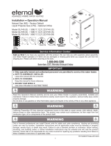
Service Information Center:
Call us rst if you have any questions with this product. We can help you with questions about assembly
and Water Heater operation or if there are any damaged or missing parts when you unpack this unit from the
shipping box. Please call before returning to the store.
1-866-946-1096
7am-7pm CST, Monday through Friday
157140081 Date 2011/5/23
Installation ● Operation Manual
Natural Gas (NG) - Factory Default
Liquid Propane Gas (LPG) - Optional Orice
Model GU145 (S) / 508(11,12,21,22)1145 (S)
Model GU195 (S) / 508(11,12,21,22)1195 (S)
Model GU195 (M) /
508(11,12,21,22)1195 (M)
California Proposition 65 lists chemical substances known to the state to cause cancer, birth defects, death,
serious illness or other reproductive harm. This product may contain such substances, be their origin from fuel
combustion (gas, oil) or components of the product itself.
WARNING
! !
Read this Operator's Manual carefully and be sure your Water Heater is properly assembled, installed and
maintained. Failure to follow these instructions exactly could result in re, explosion, serious bodily injury and/or
property damage.
Do not store or use gasoline or other ammable vapors and liquids in the vicinity of this or any other appliance.
WARNING
! !
IMPORTANT:
●
Only specially trained and authorized personnel are permitted to service this water heater.
●
NOTE TO ASSEMBLER / INSTALLER:
Leave this manual with the consumer.
●
NOTE TO CONSUMER:
Keep this manual for future reference.
●
RECORD YOUR SERIAL #________________
(see silver CSA label on Gas Water Heater)
C
Only a licensed professional can install Eternal units for safety and code compliance. Venting and plumbing
codes can vary by location. Installation instructions and all applicable codes must be followed or property
damage, severe injury, or death may result. Failure to use a licensed plumber or contractor, follow venting,
plumbing, and building codes; or follow installation instructions may be unlawful and will void the product
warranty. Grand Hall is not responsible for any costs incurred for repairing any problems resulting from failure to
follow installation instructions or applicable codes.
WARNING
! !
1

2
Table of Contents
Included & Optional Accessories P3
Specifications P4
Dimensions P5
Parts & Service Parts List P6~10
Pre-Installation Instructions for Your Safety P11
Installation Preparation P12
Condensate Disposal P13
Indoor & Outdoor Installation P14~15
Mobile Home Installation & EC Adapter Installation P16
Wall & Floor Mounting P17~18
Venting Intake & Exhaust Material P19
Direct and Power Venting P20
Vertical & Horizontal Termination P21~22
Clearance Requirements from Vent Terminations to Building Openings P23
Multiple Units Termination P24
Common Venting Installationmon Vent Installation P25
Concentric Vent Kit & Outdoor Vent Kit Installation P26
Vent Pipe Installation & Terminator Position P27
Gas Supply Piping P28
LP Conversion P29
Water Supply Connection P30
Condensate Piping P31
Temperature and Pressure Relief Valve & Recirculation Pump Connection P32
Electrical Connection P33
Optional Remote Controller Installation P34~35
MCU Installation P36~38
Plumbing Diagrams P39~43
Operating Instructions P44
How To Use The Front Control Interface P45
How To Use the Remote Controller P46
Maintenance and Service P47
"D" button Diagnostic Function P48
Diagnostics P49~51
How To Check Gas Combustion P52~53
Wiring and Connection Diagram P54~55
Grand Hall Limited Warranty P56

3
Included Accessories
Optional Accessories
0.75mm*2C
Wire
Hole Plug : 1pcs
Self Tapping Screw
5/32" x 5/8" : 2pcs
Cap : 2pcs
Philips Head Screw
M8x15 : 4pcs
Stainless Steel Expansion Bolt
: 4pcs
Item Description Qty
273
Eternal Hybrid
Condensing
Water Heater
Operating and
Installation Manual
Registration Card
151140066
151140067
T&P Relief Valve
Drain Valve
Assembly
Mesh Screen
1
1
1
1
2
190006019
1
P/N Item Description QtyP/N
Propane Gas Label
1
1
Outdoor Venting
Cap
Concentric Kit
Horizontal
Terminator 3"
1
508111145(S)
157140081
157010178
314070066
194140151
305070273
151140097
157010126
Item Description QtyP/N Item Description QtyP/N
314070074 ECHCVT01
151140130
GU145(S)
GU195(S)
Eternal Condensate
ECHNK01
Neutralizer Kit
GU195(M)
508111195(S)
508111195(M)
1
Remote Controller
Kit
314070039
1
1
ECHNR01 Eternal Condensate
Neutralizer Refill
Mounting Bracket x2pcs
Wall Bracket x1pcs
1/4"x1 12" screws x6pcs
1
LP Orifice
1
150150197
Mounting Bracket
Assembly
Water Heater
Stand
314080136
1
1
T-Fitting
195140195
(for condensate line)
1
EC Adapter
312070025
Item Description Qty
273
Eternal Hybrid
Condensing
Water Heater
Operating and
Installation Manual
Registration Card
151140066
151140067
T&P Relief Valve
Drain Valve
Assembly
Mesh Screen
1
1
1
1
2
190006019
1
P/N Item Description QtyP/N
Propane Gas Label
1
1
Outdoor Venting
Cap
Concentric Kit
Horizontal
Terminator 3"
1
508111145(S)
157140081
157010178
314070066
194140151
305070273
151140097
157010126
Item Description Qty
P/N Item Description QtyP/N
314070074 ECHCVT01
151140130
GU145(S)
GU195(S)
Eternal Condensate
ECHNK01
Neutralizer Kit
GU195(M)
508111195(S)
508111195(M)
1
Remote Controller
Kit
314070039
1
1
ECHNR01 Eternal Condensate
Neutralizer Refill
Mounting Bracket x2pcs
Wall Bracket x1pcs
1/4"x1 12" screws x6pcs
1
LP Orifice
1
150150197
Mounting Bracket
Assembly
Water Heater
Stand
314080136
1
1
T-Fitting
195140195
(for condensate line)
1
EC Adapter
312070025

4
Eternal Hybrid Water Heater Technical Specications
Model Name
GU145 / GU145(S) GU195(S) / GU195(M)
Thermal Efciency (*) / Energy Factor 98% NG / 99% LP / 0.96 Energy Factor
Installation Indoor / Outdoor / Wall Hung / Floor Standing
Flue System Sealed Combustion Direct Vent / Power Vent Convertible
Vent Run 3" PVC / 2" PVC Up to 100ft, 6 Elbows Max, 5ft Deduction Per Elbow / Up to 35ft,
3 Elbows Max, 5ft Deduction Per Elbow
Condensate Discharge Low Fire / Med Fire / High Fire 0.5GPH / 1.1GPH / 1.75GPH
Condensate pH Level 4 pH
Gas Type Pre-set for NG / LP Conversion Kit Included
Unit Connections Gas and Water 3/4" Female NPT
Electricity Dedicated 120VAC, 60Hz w/3 Pronged Power Cord
Gas Input Rate Min / Max 31,000 BTU/Hr / 145,000 BTU/Hr 31,000 BTU/Hr / 199,000 BTU/Hr
Gas Supply Pressure NG / LP 3.5" WC to 10.5" WC / 8" WC to 14" WC
Manifold Pressure
(minimum)
Time engineering
NG (
-
) 0.02" W.C. NG (
-
) 0.02" W.C.
PG (
-
) 0.02" W.C. PG (
-
) 0.02" W.C.
Honeywell
NG (
-
) 0.01" W.C. NG (
-
) 0.01" W.C.
PG (
-
) 0.01" W.C. PG (
-
) 0.01" W.C.
Ignition System Direct Electronic Ignition w/Automatic Flame Sensing
Burner System Single Orice Premixed Fuel Injection Metal Fiber Infrared
Gas Valve System Dual Stage Negative Pressure Full Modulation Air Ratio
Internal Piping Material Stainless Steel
Reserve Tank 2 Gallons
Electrical Consumption Standby 8W, Max 45W Standby 8W, Max 85W
Maximum Noise Level 40dB (a) 50dB (a)
Remote Controller Up to 3 kits
Multi Unit Capable Up to 2 in manifold, No Built - In MCU / M Option - MCU up to 8 Units
GPM Capacity Range 0.1 to 14.5 GPM 0.1 to 19.5 GPM
Temperature Sensing Tank, Cold Inlet, Hot Outlet, Air Thermistors
Temperature Control
Simulation Feed Forward and Feed Back, Computer Controlled Mixing Valve
Flow Sensing Dual Flow Sensors w/Built-in GPM Monitor
Temperature Settings Range 100°F to 180°F in 5°F Steps, Factory Limited to 140°F
Unit Dimensions (WxHxD) 16.9" x 29.1" x 13.8"
Unit Weight 90Ibs / M Option - 91.5Ibs
Safety Devices T&P Valve, Flame Rod, Thermal Fuse(306°F), Remaining Flame
Detection, Fan RPM Check, Freeze Protection(-40°F), Vent Blockage
Detection, Thermostat Switches(167°F / 203°F), Gas Valve Current
Leak Detection, Ignition Prevention, Dipswitch Temperature Lock, GFCI
w/2 x 5A Fuses.
* 2"PVC Cannot be used at elevations above 4,000ft.
GU145S and GU195S are for single or dual unit applications with no multi control unit. The GU195M is for
multiple unit applications only and cannot be used for single unit applications.
* Maximum manifold pressure is indicated on the rating label on right side of the unit.
* Independent DOE tested.

5
Dimensions - GU145(S) / 508(11,12,21,22)1145(S)
GU195(S,M) / 508(11,12,21,22)1195(S,M)

6
Parts Diagram for Model GU145(S) / 508(11,12,21,22)1145(S)
GU195(S,M) / 508(11,12,21,22)1195(S,M)
11
12
5
9
13
6
14
3
4
7
2
10
1
15
8
18
16
17
19
7
20
31

7
Parts Diagram for Model GU145(S) / 508(11,12,21,22)1145(S)
21
22
23 24
25
26
2728
29
30

8
KEY DESCRIPTION
1 Panel, Front Assembly
2 Panel, Top / Rear Assembly
3 Panel, Rear
4 Panel, Left Assembly
5 Panel, Right Assembly (GU145(S))
6 Panel, Bottom
7 Mounting Bracket
8 Wall Bracket
9 Controller / Front
10 T&P Relief Valve (Cash Acme)
11 Vent Collar
12 Vent Collar Packing
13 Rubber Foot
14 Drain Valve Assembly
15 Main Power Cord
16 Handle
17 Condensing Nipple
18 Plug
19 Mesh Screen
20 Outdoor Venting Cap (Optional)
21 Trap Cleaner Assembly
22 Radial Blower Assembly
23 Gas Valve
24 Air Pressure Switch (GU145(S))
25 Burner Assembly
26 Main Controller (GU145(S))
27 Cold Water Tube Assembly (GU145(S))
28 Hot Water Tube Assembly (GU145(S))
29 Flexible Silencer Kit
30 Mixing Valve
31 EC Adapter
Parts List for Model GU145(S) / 508(11,12,21,22)1145(S)

9
Parts Diagram for Model GU195(S) / 508(11,12,21,22)1195(S)
Parts Diagram for Model GU195(M) / 508(11,12,21,22)1195(M)
21
22
23 24
25
26
2728
29
30
21
22
23 24
26
2728
30
25
29
30

10
Parts List for Model GU195(S,M) / 508(11,12,21,22)1195(S,M)
KEY DESCRIPTION
1 Panel, Front Assembly
2 Panel, Top / Rear Assembly
3 Panel, Rear
4 Panel, Left Assembly
5 Panel, Right Assembly (GU195(S,M))
6 Panel, Bottom
7 Mounting Bracket
8 Wall Bracket
9 Controller / Front
10 T&P Relief Valve (Cash Acme)
11 Vent Collar
12 Vent Collar Packing
13 Rubber Foot
14 Drain Valve Assembly
15 Main Power Cord
16 Handle
17 Condensing Nipple
18 Plug
19 Mesh Screen
20 Outdoor Venting Cap (Optional)
21 Trap Cleaner Assembly
22 Radial Blower Assembly
23 Gas Valve
24 Air Pressure Switch (GU195(S,M))
25 Burner Assembly
26 Main Controller (GU195(S,M))
27 Cold Water Tube Assembly (GU195(S,M))
28 Hot Water Tube Assembly (GU195(S,M))
29 Flexible Silencer Kit
30 Mixing Valve
31 EC Adapter

11
Pre-Installation Instructions for Your Safety
WARNING
If you do not follow these instructions exactly, a re or explosion could result causing property damage, personal
injury or loss of life.
WHAT TO DO IF YOU SMELL GAS
Do not try to light any appliance.
Do not touch any electrical switch; do not use any phone in your building.
Immediately call your gas supplier from a neighbor's phone. Follow the gas supplier's instructions.
If you cannot reach your gas supplier, call the re department.
Use this water heater at your own risk. The set outlet water temperature can cause severe burns instantly
or death from scalds. Test the water before bathing or showering. Do not leave children or the inrm without
supervision.
Installation Codes
Before Installation
The installation must conform with local codes or, in the absence of local codes, with National Fuel Gas Code,
ANSI Z223.1/NFPA 54.
Properly ground the unit in accordance with all local codes or in the absence of local codes, with the National
Electrical Codes, ANSI/NFPA 70.
This water heater does not have a pilot. It is equipped with an ignition device that automatically lights the burner.
Do not try to light the burner by hand.
Smell all around the water heater area for evidence of leaking gas. Be sure to smell next to the oor because LP
gas is heavier than air and will settle on the oor.
Use only your hand to turn the manual gas valve knob. Never use tools. If the knob will not turn by hand, don't try
to repair it. Call a qualied service technician. Force or attempted repair could result in a re or explosion.
Do not use this water heater if any part has been under water. Immediately call a qualied service technician to
inspect the water heater and to replace any damaged parts.
Far away from water heater
In approved containers
Tightly closed
Out of children's reach
Cannot be seen
Vapors are heavier than air
Go a long way on the oor
Can be carried from other rooms to the main burner by air currents
Turn off all electrical power to the water heater if service is to be performed.
Turn the manual gas valve located on the outside of the unit clockwise to the off position.
Vapors from ammable liquids will explode and catch re causing death or severe burns. Do not use or store
ammable products such as gasoline, solvents or adhesives in the same room or area near the water heater.
□
□
□
□
□
□
□
□
□
□
□
□
□
□
□
□
Keep ammable products
Vapors
TO TURN OFF GAS TO WATER HEATER
WARNING
WARNING
WARNING
□
□
□
□
! !
! !
! !

12
Installation Preparation
Unpack the unit carefully and make sure that all accessories are put aside so they will not be lost.
● Operator's manual ● Warranty Registration Card ● Included Parts
Inspect the water heater for possible shipping damages.
Check the markings of the rating plate on the water heater to be certain the type of gas being furnished
corresponds to what the water heater is equipped for.
Do not connect this water heater to a fuel type not in accordance with the rating plate.
Carefully choose the location for the new heater as placement is a very important consideration for the safety of
the occupants in the building and for the most economical use of the appliance.
Whether replacing an old water heater or putting the water heater in a new location, consider the following critical
points:
Read the Safety guidelines in the beginning of this manual.
The internal computer controlled regulator is preset by the manufacturer and should not be adjusted by user.
Maintain proper space around the unit for servicing. Install the unit so that it can be connected or removed
easily.
The electrical connection requires a means for switching off the power supply.
Avoid installing the unit in an area with high levels of dust, sand, or debris. These particles may clog the air
vent or impair the function of the fan, leading to improper combustion. Regular maintenance is needed.
Do not install the unit where the exhaust vent is pointing into any opening in a building or where the noise may
disturb neighbors.
The location selected should be as close to the vent termination point as possible, and centered within the
water piping system for best hot water delivery. All water heaters can leak. Do not install without adequate
drainage provisions where water flow can cause property damage.
If vented through an outside wall or through the roof using 3" vent piping the total vent run cannot exceed 95
feet with one 90° elbow. If more elbows are required the venting distance must be reduced 5 feet for every 90°
elbow.
Vent piping should slope downward towards the unit. Horizontal runs require adequate support at 3½ feet
intervals and vertical runs supported at 5 feet intervals.
Condensation may be created at times as the combustion gases exit the vent cap. Discoloration of surfaces in
proximity to the vent cap may occur.
□
□
□
□
□
□
Unpacking Your Eternal Water Heater
Additional Safety Instructions
WATER HEATER PLACEMENT
●
●
●
●
●
●
●
●
●
●
Before Commencing The Installation
Check that it is in accordance with relevant building and mechanical codes, as well as any local, state or federal
regulations.
WARNING
The appliance should be located in an area where leakage of the tank or connections will not result in damage
to the area adjacent to the appliance or to lower floors of the structure. When such locations cannot be
avoided, it is recommended that a suitable drain pan be installed under the appliance. The pan must not restrict
combustion air ow.
The minimum inlet gas pressure must be within the value specied by the manufacturer and the minimum value
listed is only for the purpose of input adjustment.
If a water heater is installed in a closed water supply system, such as one having a backow preventer in the
cold water supply line and a thermal expansion tank is required, contact the water supplier or local plumbing
inspector on how to control this situation.
The Temperature and Pressure (T&P) relief valve must be certied as meeting the requirement of the Standard
for Relief Valves and Automatic Gas Shut-off Devices for Hot Water Supply Systems ANSI Z21.22/CAN1-
4.4. The valve must be marked with a maximum set pressure not to exceed the marked hydrostatic working
pressure of the water heater (150 psi) and a discharge capacity not less than the water heater input rate as
marked on the rating plate.
□
□
□
□
WARNING
CAUTION
! !
! !

13
Condensate Disposal
The condensate drain must be lled and unobstructed to allow ow of condensate. The condensate should not
be subjected to conditions where freezing could occur. If the condensate is subjected to freezing or obstruction, it
can leak, resulting in potential water damage to the unit and surrounding area.
The drain line material must be an approved material by the authority having jurisdiction. In absence of such
authority, PVC and CPVC piping must comply with ASTM D1785 or D2845. This pipe must be connected to the
port at the side panel. The end of the pipe should drain to a laundry tub or to a oor drain.
Over time, blockage of the trap by debris may occur; when the condensate cannot be released, the unit will go into
error and will shut down. When this occurs, the trap must be cleaned.
CLEANING OUT THE TRAP
The condensate trap must be lled with water prior to using the water heater.
Fill 3.0 oz. of water through the exhaust collar per gure 1.
Eternal water heater will typically produce a condensate that is considered slightly acidic with a Ph content of
approximately 3-4. Install a neutralizing lter if required by authority having jurisdiction (See gure 2).
Direct to drain from the unit.
Drain through neutralizer from the unit.
Drain to laundry tub from the unit, in this case the unit must be above the height of the laundry tub.
When installing a condensate pump, ensure the pump is approved for use with condensing appliance.
The pump should be equipped with an overow switch to prevent property damage from potential condensate
spillage.
1.
2.
3.
4.
CAUTION
Figure 2.
3/4" PVC pipe
Figure 3.
NOTICE
NOTICE
□
To Remove Trap
1. Gently pull trap body downwards to remove.
2. Remove clip securing trap to the nipple.
! !
! !
! !
4
12
3
1
2
3 oz.
Figure 1.
4
12
3
1
2

14
Indoor Installation
Clearances
From top of water heater 12 inches From back of unit 0.6 inch
From front of unit 6 inches (*) From left side of unit (gas piping side) 6 inches
From side wall ue or vent connector in any direction 6 inches From right side of unit 2 inches
GU145(S) / GU195(S,M) can be used as either Power-Vent or Direct-Vent appliance. When used as a Power-
Vent appliance, the water heater should be located in an area where enough air is available for proper
combustion and ventilation. Follow the latest edition of ANSI Z223.1 and any of your local codes that are
applicable.
GU145(S) / GU195(S,M) is a Category IV vented appliance and manufacturer's ventilation specifications should
be followed.
In general these requirements specify that if the unit is installed in a confined space, there must be permanent air
supply openings if Eternal isn't installed as Direct-Vent.
When combustion air is supplied directly through an outside wall such as intake louver openings into the dwelling,
each opening should give a minimum free area of one square inch per 15,000 Btu/hour of the total input ratings of
all appliances in the enclosed area.
When combustion air is supplied from inside the building, each opening should give a minimum free area of one
square inch per 3,750 Btu/hour of the total input ratings of all appliances in the enclosed area. These openings
should never be less than 40 sq.in.
The minimum required inside air volume should be 50 cu.ft per every 3,750 Btu/hour.
□
□
□
Combustion Air Supply
Air supply from outside building:
Air supply from inside building:
Minimum Recommended Air Supply To Water Heater as Power-Vent
Model # Water Heater Capacity Outside Air Area Inside Air Area
GU195 (S,M) Max. 199,000 Btu/hour 14 sq.in. 54 sq.in.
GU145 (S) Max. 145,000 Btu/hour 10 sq.in. 40 sq.in.
Model # Water Heater Capacity Minimum Required Air Volume
GU195 (S,M) Max. 199,000 Btu/hour 2649 cu.ft
GU145 (S) Max. 145,000 Btu/hour 1932 cu.ft
Improper installation can cause nausea or asphyxiation from carbon monoxide and ue gases which could result
in sever injury or death. For installation in altitudes above 4,500 feet, contact the manufacturer for installation
instructions.
WARNING
! !
Air Vents
Heater
Air Vents
Heater
*For accessibility when performing maintenance, 24" clearance in front of the unit it is recommended.

15
Outdoor Installation
Clearances
From top of water heater 24 inches From back of unit 0.6 inch
From front of unit 24 inches From left side of unit (gas piping side) 6 inches
From side wall ue or vent connector in any direction 6 inches From right side of unit 2 inches
If this unit is installed under an overhang, there must be a 24" clearance from the top of the unit to the overhang,
and the surrounding area must be open in front and on the sides of the unit.
For outdoor installation, do not remove the vent cap from the top of the appliance. Locate the water heater in an
open, unroofed area, and maintain the above minimum clearances from combustible materials.
□
Exhaust Ventilation
Do not have the ue terminal pointing toward an opening into the building. Do not locate your heater in a pit or
any location where gas and water can accumulate.
WARNING
! !
Do not install the water heater where water, debris or ammable vapors may get into the ue terminal. This may
cause damage to the water heater.
WARNING
! !
Improper installation can cause nausea or asphyxiation from carbon monoxide and ue gases which could result
in severe injury or death. For installation in altitudes above 4,500 feet, contact the manufacturer for installation
instructions.
WARNING
! !
Min. 1ft

16
Mobile Home Installation
Read and Review this entire Manual with special emphasis on combustion and ventilation for your safety.
If you do not follow these instructions exactly, a re or explosion could result causing property damage, personal
injury or loss of life.
WARNING
! !
Eternal water heater must be used as a sealed combustion type (Direct Vent) where all the combustion air is
supplied from the outdoors through the air intake and all combusted gas byproduct is vented directly to the outside
by means of the vent termination.
MOBILE HOME (Manufactured Home).
This appliance must be installed in accordance with the Manufactured Home Construction And Safety
Standard,(Title 24, CFR; Part 3280). In addition, install in accordance with the following instructions, the instructions
supplied with the venting termination, local codes, utility company requirements for the installation of water heaters
in manufactured homes (mobile homes). In the absence of such a standard, the water heater should be installed
in accordance with the latest edition of the National Fuel Gas Code, ANSI Z223.1/NFPA 54 and ANSI A119.5/NFPA
501D.
LOCATION for MOBILE HOME (Manufactured Home).
Per code, water heaters must be installed with a sealed combustion design so as to separate the water heater's
combustion and venting system from the interior atmosphere of the manufactured home and trailer. In accordance
with code - water heaters must be direct vented. Please refer to direct venting instructions and diagrams on page 21.
Placement of Water Heater: Locate the water heater as desired, make certain the minimum clearances are
maintained. For indoor and outdoor installation follow entire Eternal operation manual, please see section above on
manufactured home and recreational park trailer outdoor installation.
When installing in a garage, the heater's ignition source should be elevated no less the 18" from the oor unless the
ooring is listed as being resistant to the ignition of ammable vapors.
Operations Manual should be attached to the unit after installation.
EC Adapter Installation
□
How to install the EC Adapter
Loosen M10 screw.
Insert the combustion probe.
After test, retighten M10 screw on the EC Adapter
and make sure no leak.
How to test exhaust combustion air
1.
2.
3.
□
EC Adapter
M10 Screw
(Test Hole)
combustion probe
M10 Screw O Ring
Note: It is not necessary to glue the EC Adaptor into the top of the unit, but when installing PVC vent pipe into EC
Adaptor it is recommended you glue the PVC into the EC Adaptor.
For outdoor installation, please install EC Adapter to check gas setting prior to install outdoor venting cap or
PVC vent pipe.
Note:

17
Wall Mounting
The water heater must be properly supported; if the wall is not strong enough, be sure to reinforce the wall.
The unit must be mounted on a vertical wall and level to the ground.
Mounting Steps
1. Install mounting brackets with 6 screws on top and bottom back of the unit.
Select a location on the wall to mount the unit. The included wall bracket has been pre-drilled for easy installation
on standard stud walls. If the framing is not standard or installing on an uneven surface, fasten 3/4" plywood to
the stud wall and then attach the wall bracket.
Hang the unit on the mounted wall bracket and secure bottom of the unit to the wall with included wall anchors
and wall screws.
2.
3.
WARNING
1/4"x1 ½" Screws
! !
Wall Mounting For Commercial Food Service
Per ANSI / NSF-5, the unit must be mounted at least 6" above the oor from the base of the unit.
This mounting clearance provides access for clearing any possible debris or accumulated water seepage that can
occur below the unit.
Philips Head Screws
1/4"x3/8"
Philips Head Screws
1/4"x3/8"
1/4"x1 ½" Screws
6"

18
Floor Mounting
GU145(S) / GU195(S,M) can be installed standing on combustible floor surface, or on a water heater stand.
Be sure to use a suitable draining pan under the unit if leakage of the tank or connections will resuit in damage to
the area adjacent to the appliance.
Place unit directly on an even surface. Factory installed rubber feet can be adjusted if the surface is slightly uneven.
Secure the unit to the wall with included wall mount bracket. Be sure to install the wall mount bracket to the wall studs.
Per ANSI / NSF-5, floor standing directly on the hard surface is NOT an acceptable installation method. The unit
must be elevated at least 6" off the floor. This mounting clearance provides access for clearing any possible debris
or accumulated water seepage that can occur below the unit. Install the unit on Eternal Water Heater Stand (P/N
314080136) that raises the unit at least 6" above the floor.
□
□
Standing Installation
Floor Standing
Earthquake Proong
Water Heater Stand For Commercial Food Service
6" min
Factory Installed Rubber Feet
If local codes require the water heater to be raised 18" above oor, installing GU145(S) / GU195(S,M) on the
included Eternal Water Heater Stand (P/N 314080136) will satisfy code. In conjunction, the unit on stand raises
the FVIR compliant igniter and burner at least 18" off the oor. Alternatively, raising the unit at least 6" off the oor
will also satisfy code.
CAUTION
! !
Philips Head Screws
M8x15x4pcs

Eternal Hybrid Water Heater is a gas burning appliance with fan-assisted exhaust. The appliance must be vented
with 2" or 3" Category IV special venting, which is air tight to prevent leakage of exhaust gases.
The appliance must be vented separately from all other appliances. The following type of non-metallic vent can be
used:
Vent Pipe Material
All primers, cleaners and cements must meet all local codes and applicable standards of the American Society for
Testing Materials (ASTM).
Cementing PVC, ABS or CPVC PIPE and FITTING
The following guidelines should be followed when installing the exhaust outlet piping:
Venting should be as direct as possible with a minimum number of pipe ttings.
Venting diameter must not be reduced unless specially noted in the installation instructions.
Support all horizontal pipe runs every 3½ feet according to local codes.
Vents running through unconditioned spaces where below freezing temperatures are expected should be
properly insulated to prevent freezing. For horizontal runs, wrap the vent pipe with self-regulating 3 or 5 watt
heat tape. The heat tape must be U.L. listed and installed per manufacturer's instructions.
Do not connect this venting system with an existing vent or chimney.
Do not connect common vent with the vent pipe of any other water heater or appliance.
□
□
□
□
□
□
NOTICE-VENTING GUIDELINES
! !
This water heater must be properly vented for removal of exhaust gases to the outside of the home. Correct
installation of the vent pipe system is mandatory for the safe and efcient operation of this water heater and is an
important factor in the life of the unit.
WARNING
! !
If the Eternal combustion air inlet is located in an area likely to cause or contain contamination, the combustion
air must be repiped and terminated at another location. Contaminated combustion air will damage the unit and its
burner system, resulting in possible severe personal injury, death or substantial property damage.
WARNING
! !
For installations in Canada, eld supplied plastic vent piping must comply with CAN/CGA-B149.1(latest edition)
and be certied to the Standard For Type BH Gas Venting Systems,ULC S636 Components of this listed system
shall not be interchanged with other vent systems or unlisted pipe/ttings. All plastic components and specied
primers and glues of the certied vent system must be from a single system manufacturer and not intermixed
with other system manfacturer's vent system parts.
The supplied vent connectors are certied as part of the water heater.
WARNING
! !
19
Venting Intake & Exhaust Material
PVC (schedule 40, ASTM-D1785) CPVC (schedule 40, ASTM-D2846)
PVC-DWV (ANSI/ASTM-D2665) ABS (schedule 40, ASTM-D2661)
PP Pipe Single wall & Components (ULC-S636)
Note : Do not use cellular foam core pipe.
●
●
●
●
*
●

20
Direct And Power Venting
GU145(S) / GU195(S,M) is factory configured as a sealed combustion unit with dedicated intake and exhaust
connections.
When installed as a Direct Vent appliance, all combustion air is drawn directly from outside of the home.
Direct Vent configuration is suitable for indoor only.
Recommended for facilities with difficulty accessing combustion air.
When installed outdoors, outdoor venting cap should be used.
Can be installed indoors, if combustion air supply is sufficient.
Is not sealed combustion if intake is not used to bring air directly from outside.
□
□
□
□
□
□
□
Direct Vent
Power Vent
To configure the unit for power vent, insert a 6" section of 3" pvc and terminate the intake with a 90° elbow. Be sure
to insert the included mesh screen into the intake hole before the PVC pipe.
● Reduce the maximum allowable length for each elbow used as follows:
- 45 degree elbow : Deduct 2½ feet
- 90 degree elbow : Deduct 5 feet
●
How To Congure Unit For Power-Vent
Maximum Allowable Vent and Combustion Air Piping Length
Minimum Required Air Volume
2 inch Piping 3 inch Piping
Feet Max # of 90° elbows Feet Max # of 90° elbows
35 3 100 6
Insufcient air supply used with Power Vent appliance may cause the building to experience negative pressure
inside. Negative pressure is not allowable by most building codes and can cause back drafting of cold air from
outside through the unit potentially freezing the heat exchanger.
WARNING
! !
The intake vent length can be of equal length or less; there is no balancing requirement between intake and exhaust.
2" PVC Tube
2" PVC Tube
3"x2" Reducer
3" PVC Tube
2" Elbow
2" PVC Tube Conversion
For installation in altitude over 4,000 feet, Do Not connect this venting system with 2” piping.
If vent run is started with 3" PVC, the remainder of the run should be 3" PVC.
WARNING
! !
Mesh Screen
6"
3" Elbow
3" PVC Tube
/