

- 2 -
Table of Contents
I .Product Check-list ...................................................................................................3
1.Parts list.........................................................................................................4
2. Half-Assembly type parts list ........................................................................5
II.Product Specifications.............................................................................................6
III. Introduction of Product Appearance ......................................................................6
IV.Assembly and disassembly ....................................................................................7
1. Assembly and disassembly for Disassembly type.........................................7
2. Assembly and disassembly for Half-Assembly type....................................16
3.SET-UP Position & maintenance..........................................................22
V. Introduction of Product Appearance .....................................................................22
1.Link adjustment ...........................................................................................23
Cable link SET-UP ...............................................................................23
Link main board adjustment.................................................................24
2.Adjustment...................................................................................................25
SET-UP 1SET-UP the coin entry price for each game........................25
SET-UP 2Additional tickets.................................................................26
SET-UP 3Multiple of tickets ................................................................26
SET-UP 4Game Time SET-UP ...........................................................27
SET-UP 5Basket motor AUTO test.....................................................28
SET-UP 6Ball holder motor AUTO test...............................................28
SET-UP 7Reset the top score 250 or keep the record........................28
SET-UP 8SET-UP DEMO musicON or OFF................................29
SET-UP 9Difficulty Set Up ..................................................................29
3.LED Lighting Test........................................................................................30
4.AUDIT..........................................................................................................30
5.Error code....................................................................................................31
VI.How to play ..........................................................................................................32
1.There are total 4 Stages ..............................................................................32
2.2 play types available ..................................................................................32
VII.Screw and Nut list...............................................................................................33
VIII. Wires Layout.....................................................................................................34
IX.Expended view.....................................................................................................37

- 3 -
Precautions
First, we would like to thank you for choosing our product. We hope you will read the
manual before use to maintain user safety and ensure proper operation of the product. In this
manual you will find product features, precautions and some simple troubleshooting methods.
Please keep this manual in case of future problems or accidents.
Notice
After assembly, please check to ensure wires are in the proper
positions.
After set up is completed, you can plug in and turn on the machine.
Turn off the machine before moving to prevent damage.
I .Product Check-list
Before using the product, please ensure the product content is correct. If anything is
missing please contact us. Please also ensure all attached parts are included.
NO Items Specification Total quantity
1 Chassis items Packing 1 unit
2 Basketball Sonic No.5 Basketball 10 unit
3 Key(702) Maintenance door 1 pc
4 Key(436) Cash box 1 pc
5 AC cable line 1 unit
6 Operation manual A4 1 set

- 4 -
1.Parts list
1A Sensor for basket
(WO-RNPW2)
1B Basket kits
2A Basket board
2BR Back right net
stander kit
2C 2 Front net
stander
bridge(short)
2BL Back left net
stander kit
2E 2 Front net
stander bridge(long)
3A Front right net
stander kit
3B Front left net
stander kit
4A Base holder BF
4B Base holder FB
4C Base holder FF
4D Base holder BB
4E Base holder FF
(Bottom)
5A Wooden board
A type
5B Ball holder kit
5C Ball guide kits
6A Ball net holder kit
6B Main part
Basketball
6ERabber pad
Top cover
Metal Shelf
(optional)
Lower Side Net
(Frame Included)×4

- 5 -
2. Half-Assembly type parts list
4B Base holder FB
4C Base holder FF
Top cover
Main frame
5B Ball holder kit
5C Ball guide kits
6A Ball net holder kit
6B Main part
Metal Shelf (optional)
Basketball
Lower Side Net(Frame Included)×4

- 6 -
II.Product Specifications
Machine Dimensions : W1030×D2500×Top cover H2643mm
Weight : 260 kg / 558.4 lbs (Accessories not Included )
(Top cover 6.6kg, Metal Shelf 3.4kg, Lower Side Net 4.2kg×4)
Voltage : AC110V~120V/AC220V~240V(50/60Hz) Use Electrical
plug display as a glide Located behind the machine.
Power Consumption : 200W
Fuse : 3A
Token size : Ø22mm~27mm
III. Introduction of Product Appearance
Position direction
Top cover(optional)
Running display board
2 Digital display board LED
3 Digital display board LED
Coin LED display
Ticket dispenser
Coin selector
Ticket
container
(inside)
Cash
box(inside)
Speaker
Basket
b
oard
Basket
kit
Metal Shelf
(optional)
IC Board
Power
TestAudit
Fuse
Ball
holder kit
Board cover
Basket
cover
Box cover
AC Cable line
Electrical plug display
I/O control Board
Main part
Lower Side Net (Frame Included)×4
Front
Base
Top
Back
Side

- 7 -
IV.Assembly and disassembly
1. Assembly and disassembly for Disassembly type
Step 1 :
ScrewLower Side Neton the basket board front.
Assembly parts
2BR Back right net stander kit
2BL Back left net stander kit
3A Front right net stander kit
3B Front left net stander kit
Lower Side Net(Frame Included)
screw(M4×10)×12
screw(M4×10)×12

- 8 -
Step 2 :
Screw1B Basket kitson the basket board front.
screw(M5×15)×6
nut(M5)×6
Assembly parts
1A Sensor for basket
1B Basket kits
2A Basket board

- 9 -
Step 3 :
1. Screw2BR2BL Back left & right net stander kitson basket board left and right.
2. Screw2C Front net stander bridge(short)on Back left & Right net stander kits.
Assembly parts
2A Basket board
2BR Back right net stander kit
2BL Back left net stander kit
2C Front net stander
bridge(short)
screw (M6×48)×2
nut (M6)×2
Insert position
screw (M8×70)×4
nut (M8)×4

- 10 -
Step 4 :
Assemble3A3B Front right & left net stander kiton basket board left and right,
connect with screw & fixed it as drawing.
Assemb
ly parts
3A Front right net stander kit
3B Front left net stander kit
Insert
position
screw (M8×70)×4
nut (M8)×4

- 11 -
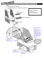
Step 5 :
Screw theBBBFFBFF Base holders & Front net stander bridge(short)step
by step as drawing.
Assembly parts
2C Front net stander
bridge(short)
2E 2 Front net stander
bridge(long)
4A Base holder BF
4B Base holder FB
4C Base holder FF
4D Base holder BB
4E Base holder FF
(Bottom)
BF
FB
screw (M6×26)×2
nut (M6)×2
screw (M6×48)×6
nut (M6)×6
(short)
screw (M6×48)
×9
nut (M6)×9
washer(M6.5×13.5)×9
FF
(long)
BB

- 12 -
Step 6 :
Screw the 5A Wooden base A type5B Ball holder kit5C Ball guide kitsstep by step
as drawing.
Wooden base A type
Ball holder kit
Ball guide kits
screw (M6×26)×12
nut (M6)×12
washer(M6.5×13.5) ×12
screw (M6×26) ×6
nut(M6) ×6
washer(M6.5×13.5) ×6
6ERubber pad
Assembly parts
5A Wooden board A type
5B Ball holder kit
5C Ball guide kits
6E Rubber pad
6ERubber pad

- 13 -
Step 7 :
1. Screw6A Ball net holder kit.
2. Screw6B Main partMetal Shelf (optional).
Assembly parts
6A Ball net holder kit
6B Main part
Metal Shelf (optional)
Ball net holder kit
Metal Shelf (optional)
Main part
screw (M8×90)×4
nut(M8)×4
sleeve(Ø15×43)×4
screw (M8×16)×4
nut (M8)×4
washer(M10×20)×4
Hexagonal Phillips
screw with 2
Washers included 2
on each side.
Tighten the screws
through the metal
shelf against the side
panel until the shelf
cannot be easily
moved.

- 14 -
Step 8 :
1.Fix the 3 main cords as the following drawing.
2.Run the IC board plug and the ball holder kit plug located underneath the front of
the ball net holder, through the hole in back of the main part.
3.Now connect plugs as shown in drawing.
Ball holder kit
Ball holder kit plug
IC board plug
Power plug
Main cords
Open main box
base a cover

- 15 -
Step 9 :
ScrewTop cover(optional)step by step as drawing.
Step 10 :
1.connect the I/O control board with Top cover.
2.Now connect plugs as shown in drawing.
Assembly parts
Top cover(optional)
Top cover(optional)
I/O control Board
Top cover
Insert position
screw (M5×38)×4
Nut(M5)×4

- 16 -
2. Assembly and disassembly for Half-Assembly type
Step 1 :
Turn the left and right frame180°to the position as drawing picture . connect with
screw & fixed it as drawing.
screw (M8×70)×4
nut (M8)×4

- 17 -
Step 2 :
Screw the base frame FB and base frame FF as drawing picture.
Assembly parts
4B Base holder FB
4C Base holder FF
FB
FF
screw (M6×26)×2
nut (M6)×2
screw (M6×48)×2
nut (M6)×2

- 18 -
Step 3 :
Screw the 5B Ball holder kit and 5C Ball guide kits as drawing picture.
Assembly parts
5B Ball holder kit
5C Ball guide kits
Ball holder kit
Ball guide kits
screw (M6×26)×12
nut (M6)×12
washer(M6.5x13.5)×12

- 19 -
Step 4 :
1. Screw6A Ball net holder kit.
2. Screw6B Main partMetal Shelf (optional).
Assembly parts
6A Ball net holder kit
6B Main part
Metal Shelf (optional)
Ball net holder kit
Metal Shelf (optional)
Main part
screw (M8×90)×4
nut(M8)×4
sleeve(
Ø
15×43)×4
screw (M8×16)×4
nut (M8)×4
washer(M10×20)×4
Hexagonal Phillips
screw with 2
Washers included 2
on each side.
Tighten the screws
through the metal
shelf against the side
panel until the shelf
cannot be easily
moved.

- 20 -
Step 5 :
1.Fix the 3 main cords as the following drawing.
2.Run the IC board plug and the ball holder kit plug located underneath the front of
the ball net holder, through the hole in back of the main part.
3.Now connect plugs as shown in drawing.
Ball holder kit
Ball holder kit plug
IC board plug
Power plug
Main cords
Open main box
base a cover
Page is loading ...
Page is loading ...
Page is loading ...
Page is loading ...
Page is loading ...
Page is loading ...
Page is loading ...
Page is loading ...
Page is loading ...
Page is loading ...
Page is loading ...
Page is loading ...
Page is loading ...
Page is loading ...
Page is loading ...
Page is loading ...
Page is loading ...
Page is loading ...
Page is loading ...
Page is loading ...
Page is loading ...
Page is loading ...
Page is loading ...
Page is loading ...
Page is loading ...
Page is loading ...
-
 1
1
-
 2
2
-
 3
3
-
 4
4
-
 5
5
-
 6
6
-
 7
7
-
 8
8
-
 9
9
-
 10
10
-
 11
11
-
 12
12
-
 13
13
-
 14
14
-
 15
15
-
 16
16
-
 17
17
-
 18
18
-
 19
19
-
 20
20
-
 21
21
-
 22
22
-
 23
23
-
 24
24
-
 25
25
-
 26
26
-
 27
27
-
 28
28
-
 29
29
-
 30
30
-
 31
31
-
 32
32
-
 33
33
-
 34
34
-
 35
35
-
 36
36
-
 37
37
-
 38
38
-
 39
39
-
 40
40
-
 41
41
-
 42
42
-
 43
43
-
 44
44
-
 45
45
-
 46
46


Ask a question and I''ll find the answer in the document
Finding information in a document is now easier with AI
Related papers
Other documents
-
GoldenEar Technology 317SAT50TS User manual
-
 Skee Ball HOT SHOT Operating instructions
-
 Namco Bandai Games Welder 90500019 User manual
-
DSE DK-BK1 Owner's manual
-
 Bay Tek Games Chameleon Paradize User manual
-
 Universal Space Extreme Hoops Operating instructions
-
 Tecway Kidde Dozer User manual
-
Bandai Namco 20211027 Ball Madness User manual
-
 Bay Tek Games Arctic Chomp User manual
-
AMI 26685001 Installation guide


