Page is loading ...

ATR144
User manual / Manuale d’uso
Controller / Regolatore


Table of contents
1 Introduction ............................................................................................................. 6
2 Safety guidelines .................................................................................................... 6
2.1 Environmental policy / WEEE ................................................................. 7
3 Model identification ..............................................................................................7
4 Technical data .......................................................................................................... 7
4.1 General features .......................................................................................... 7
4.2 Hardware features ...................................................................................... 8
4.3 Software features ........................................................................................9
4.4 Programming mode ..................................................................................9
5 Dimensions and installation ............................................................................10
6 Electrical wirings ...................................................................................................10
6.1 Wiring diagram .......................................................................................... 11
7 Display and key functions ................................................................................. 16
7.1 Numeric indicators (display).................................................................16
7.2 Meaning of status lights (Led) ............................................................. 17
7.3 Ke ys ................................................................................................................. 17
8 Controller Functions ...........................................................................................18
8.1 Modification of main and alarm setpoint value ........................... 18
8.2 Automatic Tune..........................................................................................18
8.3 Manual Tune ................................................................................................ 19
8.4 Tuning performed once ......................................................................... 19
8.5 Synchronized Tuning ...............................................................................20
8.6 Digital input functions ............................................................................21
8.7 Automatic / Manual regulation for % output control ................23
8.8 Loop Break ...................................................................................................24
8.9 Dual Action (Heating-Cooling) ............................................................ 25
8.10 Funzione LATCH ON .................................................................................28
8.11 Soft start function .....................................................................................29
8.12 Pre-programmed cycle ...........................................................................30
9 Serial communication ........................................................................................31
9.1 Slave................................................................................................................31
9.2 Master ............................................................................................................39
10 Reading and configuration through NFC ................................................... 42
11 Access configuration ...........................................................................................44
11.1 Loading default values ...........................................................................45
11.2 Parameters list functioning ..................................................................45
12 Table of Configuration Parameters ...............................................................46

13 Alarm Intervention Modes................................................................................80
13.1 Alarms label .................................................................................................84
14 Table of anomaly signals ...................................................................................85
Indice degli argomenti
1 Introduzione ...........................................................................................................92
2 Norme di sicurezza ..............................................................................................92
2.1 Tutela ambientale e smaltimento dei rifiuti / Direttiva WEEE 93
3 Identificazione di modello................................................................................93
4 Dati tecnici ..............................................................................................................93
4.1 Caratteristiche generali ..........................................................................93
4.2 Caratteristiche Hardware.......................................................................94
4.3 Caratteristiche software.........................................................................95
4.4 Modalità di programmazione ..............................................................95
5 Dimensioni e installazione ...............................................................................96
6 Collegamenti elettrici .........................................................................................96
6.1 Schema di collegamento .......................................................................97
7 Funzione dei visualizzatori e tasti .............................................................. 102
7.1 Indicatori numerici (display) .............................................................. 102
7.2 Significato delle spie di stato (Led) ................................................. 103
7.3 Tasti .............................................................................................................. 103
8 Funzioni del regolatore................................................................................... 104
8.1 Modifica valore setpoint principale e di allarme ...................... 104
8.2 Tuning automatico ................................................................................ 104
8.3 Tuning manuale ...................................................................................... 105
8.4 Tuning once .............................................................................................. 106
8.5 Tuning sincronizzato ............................................................................ 106
8.6 Funzioni da Ingresso digitale ............................................................ 107
8.7 Regolazione automatico / manuale del controllo % uscita.. 109
8.8 Loop Break .................................................................................................110
8.9 Funzionamento in doppia azione (caldo-freddo) ..................... 111
8.10 Funzione LATCH ON ............................................................................... 113
8.11 Funzione Soft-Start ................................................................................114
8.12 Ciclo pre-programmato .......................................................................115
9 Comunicazione Seriale ....................................................................................116
9.1 Slave..............................................................................................................116
9.2 Master ......................................................................................................... 125
10 Lettura e configurazione via NFC ............................................................... 128

11 Accesso alla configurazione .......................................................................... 130
11.1 Caricamento valori di default ............................................................131
11.2 Funzionamento della lista parametri .............................................132
12 Tabella parametri di configurazione ..........................................................132
13 Modi d’intervento allarme ............................................................................. 168
13.1 Label allarmi ............................................................................................. 172
14 Tabella segnalazioni anomalie..................................................................... 173
Index des sujets
1 Introduction ........................................................................................................ 180
2 Consignes de sécurité...................................................................................... 180
2.1 Politique environnementale / DEEE ............................................... 181
3 Identification du modèle................................................................................ 181
4 Données techniques ........................................................................................ 181
4.1 Caractéristiques générales ................................................................ 181
4.2 Caractéristiques Hardware ................................................................ 182
4.3 Caractéristiques Software .................................................................. 183
4.4 Mode de programmation ................................................................... 183
5 Dimensions et Installation ............................................................................. 184
6 Raccordements électriques .......................................................................... 185
6.1 Plan des connexions ............................................................................. 186

6 - ATR144 - User manual
1 Introduction
PID Controller ATR144 relies on Pixsys flagship programming
mode by NFC/RFID technology with dedicated App MyPixsys
for Android devices (same already used for Pixsys signal
converters and STR indicators) not requiring wirings and
power supply, allowing quick set-up/updates on site.
Availability include a model with dual analogue input and
dual analogue output for maximum flexibility of applications.
It is possible to achieve two separate heating/cooling PID
control loops in one device or to handle mathematical
operations between two process values.
The outputs can be selected as command/multiple alarm
modes/analogue retransmission. Serial communication
standard is RS485 (isolated) with Modbus RTU Master/Slave
protocol. Power supply with extended range 24 to 230V AC/
DC with galvanic insulation from the network.
2 Safety guidelines
Read carefully the safety guidelines and programming
instructions contained in this manual before connecting/
using the device. Disconnect power supply before
proceeding to hardware settings or electrical wirings to avoid
risk of electric shock, fire, malfunction.
Do not install/operate the device in environments with
flammable/explosive gases.
This device has been designed and conceived for industrial
environments and applications that rely on proper safety
conditions in accordance with national and international
regulations on labour and personal safety. Any application
that might lead to serious physical dama ge/ life risk or involve
medical life support devices should be avoided.
Device is not conceived for applications related to nuclear
power plants, weapon systems, flight control, mass transpor-
tation systems.
Only qualified personnel should be allowed to use device
and/or service it and only in accordance to technical data
listed in this manual. Do not dismantle/modify/repair any

User manual - ATR144- 7
internal component. Device must be installed and can
operate only within the allowed environmental conditions.
Overheating may lead to risk of fire and can shorten the
lifecycle of electronic components.
2.1 Environmental policy / WEEE
Do not dispose electric tools together with household waste
material. According to European Directive 2002/96EC on
waste electrical and electronic equipment and its implemen-
tation in accordance with national law, electric tools that have
reached the end of their life must be collected separately and
returned to an environmentally compatible recycling facility.
3 Model identification
The ATR144 series includes 2 versions:
Power supply 24..230 VAC/VDC ±15% 50/60 Hz – 5 Watt/VA
ATR144 -ABC 1 analogue input + 2 relays 5 A + 1 D.I/O
ATR144 -ABC-T 1 analogue input + 1 relays 5 A + 1 D.I/O
+ RS485
4 Technical data
4.1 General features
Displays 4 digits 9.6 mm (0.38 pollici), 5 digits 7.1
mm (0.28 pollici)
Op. conditions Temperature: 0-45° C -Humidity 35..95 uR%
Sealing IP65 front panel (with gasket)
IP20 box and terminals
Materials Box and front panel: PC UL94V2 self-
extinguishing
Weight Approx. 120 g

8 - ATR144 - User manual
4.2 Hardware features
Analogue
input
AI1:
Configurable via software.
Input: Thermocouple
type K, S, R, J,T,E,N,B.
Automatic compensation
of cold junction from
-25…85° C.
Thermoresistances: PT100,
PT500, PT1000, Ni100,
Ni120, PTC 1K, NTC 10K (β
3435K and β3694K), NTC
2252 (β3976K)
Input V/mA: 0-1 V, 0-5 V,
0-10 V, 0-20 o 4-20 mA,
0-60 mV.
Pot. Input: 1...150 KΩ.
Tolerance (25° C)
± 0.2% ± 1 digit
(on F.s.) for
thermocouple,
thermoresistance
and V/mA.
Cold junction
accuracy 0.1° C/°C.
Impedence:
0-10 V: Ri>110 KΩ
0-20 mA: Ri<5 Ω
0-40 mV: Ri>1 MΩ
Relay
outputs
Configurable as command
and alarm output.
Contacts:
5 A - 250 VAC
Resistive load.
SSR
outputs
Configurable as command
and alarm output. 12 V, 25 mA.
Power-
supply
Extended power-supply
24..230 VAC/VDC ±15%
50/60 Hz
Consumption: 5
Watt/VA

User manual - ATR144- 9
4.3 Software features
Regulation
algorithms
ON-OFF with hysteresis.
P, PI, PID, PD with proportional time
Proportional
band 0..9999°C o °F
Integral time 0,0..999,9 sec (0 exclude)
Derivative time 0,0..999,9 sec (0 exclude)
Controller
functions
Manual or automatic Tuning, selectable
alarm, protection of command and
alarm setpoints.
4.4 Programming mode
by keyboard ..see paragraph
software
LabSoftview
..on “Download section” of official pixsys
site: www.pixsys.net
App MyPixsys
..through download the App on Google
Play Store®, see paragraph
When activated by a reader/
interrogator supporting NFC-V protocol,
controller ATR244 is to be considered
a VICC (Vicinity Inductively Coupled
Card) according to ISO/IEC 15693 and it
operates at a frequency of 13.56 MHz

10 - ATR144 - User manual
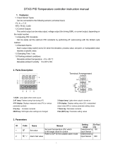
5 Dimensions and installation
+V
8 9 10 11 12
1 2 3 4 56 7
5A 230V
Resistive
1/8HP
Q2
Cla ss 2
sou rc e
24...230V
AC/DC
5A 23 0V
Resistive
1/8HP
Q1
DI/ O1
(NPN)
PTC
NTC
-
+
Tc
IV/I
+
-
PT/ NI1 00 /1K
2 wir e 4/20m A
Power
ATR144-ABC
MADE IN
EU
ATR144
FNC
SET
77 mm 953 mm
35 mm
Gasket for 32x74
Guarnizione per 32x74
Cod. 1600.00.082 (optional)
Suggested thickness
Spessore suggerito
2 ÷ 8 mm
Memory Card USB
(optional)
Cod. 2100.30.013
Frontal panel cut-out
Dima di foratura
28.5 x 70.5 mm
6 Electrical wirings
This controller has been designed and manufactured in
conformity to Low Voltage Directive 2006/95/EC, 2014/35/
EU (LVD) and EMC Directive 2004/108/EC, 2014/30/EU (EMC).
For installation in industrial environments please observe
following safety guidelines:
• Separate control line from power wires.
• Avoid proximity of remote control switches, electroma-
gnetic contactors, powerful engines.
• Avoid proximity of power groups, especially those with
phase control.
• It is strongly recommended to install adequate mains fi lter
on power supply of the machine where the controller is

User manual - ATR144- 11
installed, particularly if supplied 230 VAC.
The controller is designed and conceived to be
incorporated into other machines, therefore CE marking
on the controller does not exempt the manufacturer
of machines from safety and conformity requirements
applying to the machine itself.
• Wiring ATR244-12ABC, use crimped tube terminals or
flexible/rigid copper wire with diameter 0.14 to 2.5 mm2
(min. AWG26, max. AWG14). Cable stripping lenght 6 to 8
mm.
• It is possible to connect on a single terminal two wires with
same diameter comprised between 0.14 and 0.75mm.
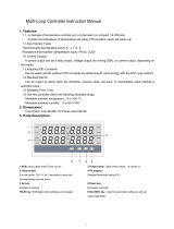
6.1 Wiring diagram
ATR144-ABC ATR144-ABC-T
+V
8 9 1 0 11 12
1 2 3 4 56 7
5A 230V
Resistive
1/8HP
Q2
Clas s 2
sour ce
24...230V
AC/DC
5A 23 0V
Resistive
1/8HP
Q1
DI/O1
(NPN)
PTC
NTC
-
+
Tc
IV/I
+
-
PT/NI100 /1 K
2 wire 4/20m A
Power
+V
8 9 1 0 11 12
1 2 3 4 56 7
Clas s 2
sour ce
24...230V
AC/DC
5A 23 0V
Resistive
1/8HP
Q1
DI/O1
(NPN)
PTC
NTC
-
+
Tc
IV/I
+
-
PT/NI100 /1 K
2 wire 4/20m A
Power
-
+
RS485
6.1.a Power supply
1
2
Class 2 source
24...230 VAC/DC
Switching power supply 24..230 VAC/
VDC ±15% 50/60 Hz - 5 Watt/VA.
Galvanic insulation.

12 - ATR144 - User manual
6.1.b Analogue input AI1
Shield/Schermo
TC
11
12 +
-
For thermocouples K, S, R, J, T, E, N, B.
• Comply with polarity
• For possible extensions, use
compensated cable and terminals
suitable for the thermocouples used
(compensated).
• When shielded cable is used, it should
be grounded at one side only.
PT/NI100
Shield/Schermo
10
11
12
For thermoresistances PT100, Ni100.
• For the three-wire connection use
wires with the same section.
• For the two-wire connection short-
circuit terminals 10 and 12.
• When shielded cable is used, it should
be grounded at one side only.
RED/ROSSO
RED/ROSSO
WHITE/BIANCO
Shield/Schermo
PTC/NTC
10
11
For thermoresistances NTC,
PTC, PT500, PT1000 and linear
potentiometers.
• When shielded cable is used, it should
be grounded at one side only to avoid
ground loop currents.
Shield/Schermo
+V V/I +-
9
10
11
12
For linear signals in Volt and mA
• Comply with polarity
• When shielded cable is used, it should
be grounded at one side only to avoid
ground loop currents.

User manual - ATR144- 13
6.1.c Examples of connection for linear input
0...10V
1211
For signals 0..10V
• Comply with polarity
0/4...20mA
B
C
11
9
12 +
+
-
For signals 0/4..20mA with three-wire
sensor
• Comply with polarity
C = Sensor output
B = Sensor ground
A = Sensor power supply (12V/30mA)
In the picture: pressure sensor.
P
N
0/4...20mA
B
C
11
12 +
-
For signals 0/4..20mA with external
power of sensor
• Comply with polarity
C = Sensor output
B = Sensor ground
In the picture: pressure sensor. Connect
the external power supply to pins P
and N.
0/4...20mA
A
C
9
12
For signals 0/4..20mA with two-wire
sensor
• Comply with polarity
C = Sensor output
A = Sensor power supply (12V/30mA)
In the picture: pressure sensor.

14 - ATR144 - User manual
6.1.d Digital input 1
+V
DI/O1
(NPN)
8
9
Digital input can be enabled by
parameter.
Close pin 8 “DI/O1” on pin 9 “+V” to
enable digital input.
6.1.e Digital input 2
10
11
Digital input can be enabled by
parameter. Not available when a
resistive sensor (thermoresistances or
potentiometers) is selected.
Close pin 10 on pin 11 to enable digital
input.
6.1.f Serial input (only on ATR144-ABC-T)
- +
Shield/Schermo
RS485
6
7
Modbus RS485 communication.
RTU Slave with galvanic insulation.
It is recommended to use the twisted
and shielded cable for communications.
6.1.g Digital output
+V
DI/O1
(NPN)
8
9
Digital output NPN (including SSR) for
command or alarm.
Range 12 VDC/25 mA.

User manual - ATR144- 15
6.1.h Relay output Q1
3
4
5
5A 230V
Resistive
1/8HP
Q1
Capacity 5 A / 250 VAC for resistive
loads.
See chart below.
6.1.i Relay output Q2 (only on ATR144-ABC)
6
7
5A 230V
Resistive
1/8HP
Q2 Capacity 5 A / 250 VAC for resistive
loads.
See chart below.
Contact Q1 e Q2:
• Rating (resistive): 250 VAC/30
VDC, 5A
• Maximum switching power:
1250 VA/150W
Life:
• Mechanical: min. 5x10⁶
operations
• Electrical: min. 100x103
operations

16 - ATR144 - User manual
7 Display and key functions
ATR144
FNC
SET
23 1
456
9
10
12
11
8 7
7.1 Numeric indicators (display)
1123.4
Normally displays the process. During
the configuration phase, it displays the
parameter groups or the parameter
being inserted.
2PRo b e
Normally displays the setpoint. During
the configuration phase, it displays the
parameter value being inserted.

User manual - ATR144- 17
7.2 Meaning of status lights (Led)
3 C
ON when the command output 1 is active. In
case of motorized valve control it is ON during
valve opening and flashes during valve closing.
4A1 ON when alarm 1 is active.
5A2 ON when alarm 2 is active.
6 T ON when the controller is executing an
auto-tuning cycle.
7 M ON when “Manual” function is active.
8 R
ON when the controller communicates through
serial. Flashes when the remote setpoint is
enabled.
7.3 Keys
9
• Increases the main setpoint.
• During configuration allows to scroll the
parameters or the groups of parameters.
• Increases the setpoints.
10
• Decreases the main setpoint.
• During configuration allows to scroll the
parameters or the groups of parameters.
• Decreases the setpoints.
11 SET
• Allows to visualize command and alarm
setpoints.
• During configuration allows to enter the
parameter to be modified and confirms the
variation.
12 FNC
• Allows to enter the Tuning launch function,
automatic/manual selection.
• During configuration works as exit key
(ESCAPE).

18 - ATR144 - User manual
8 Controller Functions
8.1 Modification of main and alarm setpoint
value
Setpoint value can be modified from keyboard as follows:
Press Display Do
1
Value on display 2
changes.
Increases or decreases
the main setpoint
value.
2SET
Visualizes the other
setpoints on display
1. Display 2 shows the
setpoint type.
3
Value on display 1
changes.
Increases or decreases
the alarm setpoint
value.
8.2 Automatic Tune
Automatic tuning procedure allows a precise regulation
without detailed knowledge of PID regulation algorithm.
Selecting Auto on par. 36 t u n .1 , the controller analyzes the
proces oscillations and optimizes the PID parameters.
Led T flashes.
If the PID parameters are not yet selected, at the device
switch-on, the manual tunig procedure described in the
next paragraph will be launched described into the next
paragraph.

User manual - ATR144- 19
8.3 Manual Tune
Manual procedure allows the user greater flexibility to decide
when to update
PID algorithm parameters. During the manual tuning, the
device generates a step to analyze the system inertia to be
regulated and, according to the collected data, modifies PID
parameters.
After selecting Manu. on par. 33 t u n .1 , the procedure can be
activated in three ways:
• Running Tuning by keyboard:
Press FNC until display 2 shows tunE with display 1 on di s .
and then press SET: display 1 shows En a b . Led T switches
ON and the procedure starts.
• Running Tuning by digital input:
Select tunE on par. 94 d.i.1.F. or on par. 101 d .i .2. F.. At first
activation of digital input (commutation on front panel)
led T led switches on and at second activation switches off.
• Running Tuning by serial input:
Write 1 on word modbus 1210: led T switches ON and the
procedure starts. Write 0 to stop the tuning.
To avoid an overshoot, the treshold where the controller
calculates new PID parameters is determined by this
operation:
Tune threshold = Setpoint - “Set Deviation Tune” (par. 37
s.d.t.1)
Ex.: if the sepoint is 100.0 °C and the Par. 37 s.d.t.1 is 20.0 °C the
threshold to calculate PID parameters is (100.0 - 20.0) = 80.0°C.
For a greater precision on PID parameters calculation it is
suggested to start the manual tuning procedure when the
process is not close to setpoint value.
8.4 Tuning performed once
Set once on parameter 36 t u n .1 , or on parameter 98 tu n .2.
Autotuning procedure is executed only once at next ATR144
restart. If the procedure doesn’t work, it will be be executed
at next restart.

20 - ATR144 - User manual
8.5 Synchronized Tuning
Set sYNch . on parameter 36 t u n .1 .
This procedure has been conceived to calculate correct PID
values on multi-zone systems, where each temperature is
influenced by the adjacent zones.
Writing on word modbus 1210 the controller works as follows:
Word
value Action
0Tune off
1Command output OFF
2Command output ON
3Tune active
4Tune completed: command output OFF (read only)
5Tune not available: softstart function enabled (only
reading)
Here below the functioning for regulation loop: the master
switches-off or turns-on all zones (value 1 or 2 on word 1210)
for a time long enough to create inertia on the system.
At this point the autotuning is launched (value 3 on word 1210).
The controller executes the procedure for the calculation of
the new PID values. When the procedure ends, the controller
switches off the command output and selects the value 4 on
word 1210. The Master, always reading word 1210, will control
the various zones and when all will have finished, it will set to
0 the value of word 1210: the various devices will regulate the
temperature independently, with the new calculated values.
N.B. The master must read the word 1210 at least every
10 seconds or the controller will automatically exit the
autotuning procedure.
/