Page is loading ...

ATR226
Controller / Regolatore
User manual / Manuale installatore


User manual - ATR227 - 3
Index
1 Safety guide lines ..........................................................................................................................................5
2 Model Identication .....................................................................................................................................5
3 Technical Data ...............................................................................................................................................5
3.1 General Features ..................................................................................................................................5
3.2 Hardware Features ..............................................................................................................................6
3.3 Software Features ...............................................................................................................................6
4 Dimensions and Installation ......................................................................................................................7
5 Electrical wirings ...........................................................................................................................................7
5.1 Wiring diagram ....................................................................................................................................8
6 Display and Keys Functions ........................................................................................................................9
6.1 Numeric Indicators (Display) ......................................................................................................... 10
6.2 Meaning of Status Lights (Led) ..................................................................................................... 10
6.3 Keys ....................................................................................................................................................... 10
7 Controller Functions .................................................................................................................................. 10
7.1 Modifying Main Setpoint and Alarm Setpoint Values ............................................................ 10
7.2 Auto-Tuning ........................................................................................................................................11
7.3 Manual Tuning ...................................................................................................................................11
7.4 Automatic Tuning ..............................................................................................................................11
7.5 Soft-Start ..............................................................................................................................................11
7.6 Automatic/Manual Regulation for % Output Control ............................................................11
7.7 Digital input functions .....................................................................................................................12
8 Conguration ...............................................................................................................................................12
8.1 Loading default values ....................................................................................................................13
9 Table of Conguration Parameters ........................................................................................................13
10 Alarm Intervention Modes ........................................................................................................................19
11 Table of Anomaly Signals......................................................................................................................... 22
12 Conguration EASY-UP ............................................................................................................................ 22
13 Summary of Conguration parameters .............................................................................................. 23

4 - ATR227 - Manuale d’uso
Sommario
1 Norme di sicurezza .................................................................................................................................... 25
2 Identicazione del modello ..................................................................................................................... 25
3 Dati tecnici ................................................................................................................................................... 25
3.1 Caratteristiche generali .................................................................................................................. 25
3.2 Caratteristiche Hardware ............................................................................................................... 26
3.3 Caratteristiche Software ................................................................................................................ 26
4 Dimensioni ed installazione .................................................................................................................... 27
5 Collegamenti elettrici................................................................................................................................27
5.1 Schema di collegamento ................................................................................................................ 28
6 Funzione dei visualizzatori e tasti .......................................................................................................... 29
6.1 Indicatori numerici (Display) ........................................................................................................ 30
6.2 Signicato delle spie di stato (Led) .............................................................................................. 30
6.3 Tasti ...................................................................................................................................................... 30
7 Funzioni del regolatore .............................................................................................................................31
7.1 Modica valore setpoint principale e setpoint di allarme......................................................31
7.2 Auto-Tuning .......................................................................................................................................31
7.3 Lancio del Tuning Manuale ............................................................................................................31
7.4 Lancio del Tuning Automatico .......................................................................................................31
7.5 Soft-Start ..............................................................................................................................................31
7.6 Regolazione automatico / manuale per controllo % uscita ................................................. 32
7.7 Funzioni da Ingresso digitale ........................................................................................................ 32
8 Accesso alla congurazione .................................................................................................................... 33
8.1 Caricamento valori di default ....................................................................................................... 33
9 Tabella parametri di congurazione .................................................................................................... 34
10 Modi d’intervento allarme ....................................................................................................................... 40
11 Tabella segnalazioni anomalie .............................................................................................................. 43
12 Congurazione EASY-UP .......................................................................................................................... 43
13 Promemoria congurazione ................................................................................................................... 44

User manual - ATR227 - 5
Introduction
Thank you for choosing a Pixsys controller.
With the ATR226 Pixsys model Pixsys makes available in a single device multiple
options related to sensor input and actuators command in addition to the extended
power range 24..230 Vac/Vdc. With the various selectable sensors and the output con-
gurable as relay or SSR command, the user or retailer can reduce stock by rationalising
investment and device availability.
1 Safety guide lines
Read carefully the safety guidelines and programming instructions contained in
this manual before using/connecting the device. Disconnect power supply before
proceeding to hardware settings or electrical wirings. Only qualied personnel should
be allowed to use the device and/or service it and in accordance to technical data and
environmental conditions listed in this manual. Do not dispose electric tools together
with household waste material. In observance European Directive 2002/96/EC on
waste electrical and electronic equipment and its implementation in accordance with
national law, electric tools that have reached the end of their life must be collected
separately and returned to an environmentally compatible recycling facility.
2 Model Identication
Power supply 24..230 Vac/Vdc +/-15% 50/60 Hz – 5,5 VA
ATR226-12ABC 2 Relays (2A) + 1 SSR + D.I.
3 Technical Data
3.1 General Features
Displays 4 0,40 inch displays+ 4 0,30 inch displays
Operating temperature 0-45 °C - Humidity 35..95 uR%
Sealing IP65 front panel (with gasket)
IP20 box and terminals
Material PC ABS UL94VO self-extinguishing
Weight 130 g

6 - ATR227 - User manual
3.2 Hardware Features
Power supply 24..230 Vac/Vdc ±15%
50/60 Hz Consumption: 5.5 VA.
Analogue input
AN1. Congurable via
software. Thermocouple
type: K, S, R, J. Automatic
compensation of cold jun-
ction from 0°C to 50°C.
Thermoresistance: PT100,
PT500, PT1000, Ni100,
PTC1K, NTC10K (β 3435K).
Tolerance (25 °C)
+/-0.3% ±1 digit (su F.s.)
Cold junction accuracy 0.1 °C/°C.
Relay outputs
2 relays congurable as
command and/or alarm
output.
Contacts
2 A - 250 V~.
Resistive loads.
SSR output
1 SSR (ATR226-12ABC).
Congurable as command
output and/or alarm
output.
12V/30mA.
3.3 Software Features
Regulation
algorithms
ON-OFF with hysteresis.
P, P.I., PID, P.D. with proportional time.
Proportional band 0..9999 °C o °F
Integral time 0,0..999,9 sec. ( excluded)
Derivative time 0,0..999,9 sec. ( excluded)
Controller functions Manual or automatic Tuning, protection of command and alarm
setpoints, activation of functions via digital input.

User manual - ATR227 - 7
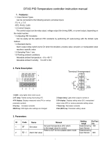
4 Dimensions and Installation
51 mm
51 mm 90 mm
7
MAN TUN REM
C 1
A 1
A 2
PTC
NTC
Dima di foratura
46 x 46 mm
Frontal panel
cut-out
Trou de panneau
Spessore suggerito 2 ÷ 6 mm
Suggested thickness 2 ÷ 6 mm
USB
ATR226
5 Electrical wirings
Although this controller was designed to resist electromagnetic interferences
in industrial environments, please observe following safety guidelines:
t 4FQBSBUFUIFDPOUSPMMJOFGSPNUIFQPXFSXJSFT
t "WPJEQSPYJNJUZPGSFNPUFDPOUSPMTXJUDIFTFMFDUSPNBHOFUJDDPOUBDUPSTQPXFSGVM
engines and in all instances use specic lters.
t "WPJEQSPYJNJUZPGQPXFSHSPVQTFTQFDJBMMZUIPTFXJUIQIBTFDPOUSPM

8 - ATR227 - User manual
5.1 Wiring diagram
ATR226-12ABC
Power Supply
Switching power supply with extended range 24..230 Vac/dc
±15% 50/60 Hz – 5,5 VA (galvanically insulated).
AN1 Analogue Input
For thermocouples K, S, R, J, T, E, N, B.
t $PNQMZXJUIQPMBSJUZ
t 'PSQPTTJCMFFYUFOTJPOTVTFDPNQFOTBUFEDBCMF
and terminals suitable for the thermocouples
used(compensated)
t 8IFOTIJFMEFEDBCMFJTVTFEJUTIPVMECFHSPVOEFEBUPOF
side only
For thermoresistances PT100, NI100
t 'PSUIFUISFFXJSFDPOOFDUJPOVTFXJSFTXJUIUIFTBNF
section
t 'PSUIFUXPXJSFDPOOFDUJPOTIPSUDJSDVJUUFSNJOBMTBOE
t 8IFOTIJFMEFEDBCMFJTVTFEJUTIPVMECFHSPVOEFEBUPOF
side only
RED
ROSSO
RED
ROSSO
WHITE
BIANCO
3
2
1
For thermoresistances NTC, PTC, PT500, PT1000 and linear
potentiometers
t 8IFOTIJFMEFEDBCMFJTVTFEJUTIPVMECFHSPVOEFEBUPOF
side only to avoid ground loop currents

User manual - ATR227 - 9
Relay Q1 - Q2 Output
Contacts capacity 5 A / 250 V~ resistive loads.
NB: see graphic below.
Electrical endurance Q1 / Q2.
2 A, 250 Vac, resistive load, 105 operations.
20/2 A, 250 Vac, cosφ = 0.3, 105 operations.
SSR output
SSR command output 12 V / 30 mA.
Digital Input
Digital input according to parameter
G*WL
.
To activate the digital input, shortcircuit pins 4 and 5.
6 Display and Keys Functions
A1
C2
C1
A2
1
3
4
8
9
2
5
6
7
10

10 - ATR227 - User manual
6.1 Numeric Indicators (Display)
1
Normally displays the process. During conguration phase, it
displays the parameter being entered.
2
Normally displays the setpoint. During conguration phase, it
displays the parameter value being entered.
6.2 Meaning of Status Lights (Led)
3C1 ON when the output command is on.
4A1 A2 ON when the corresponding alarm is active.
5MAN ON when the “Manual” function is on.
6TUN ON when the controller is running an “Autotuning” cycle.
7REM ON when the controller communicates via serial port (USB).
6.3 Keys
8
t Increases main setpoint.
t During conguration phase, allows to slide through parameters.
Together with SET it modies them.
t Pressed after
SET
increases alarm setpoint.
9
t Decreases main setpoint.
t During conguration phase, allows to slide through parameters.
Together with SET it modies them.
t Pressed after
SET
decreases alarm setpoint.
10 SET
t "MMPXTUPEJTQMBZBMBSNTFUQPJOUTBOESVOTUIF5VOJOH
function.
t "MMPXTUPNPEJGZDPOöHVSBUJPOQBSBNFUFST
7 Controller Functions
7.1 Modifying Main Setpoint and Alarm Setpoint Values
Setpoint value can be modied by keyboard as follows:
Press Display Do
1 or Value on display 2 changes. Increase or decrease main
setpoint.
2SET Visualizes alarm setpoint on
display
3 or Value on display changes .Increase or decrease the
alarm setpoint value

User manual - ATR227 - 11
7.2 Auto-Tuning
Tuning procedure to calculate regulation parameters can be manual or automatic accor-
ding to selection on parameter 8 (
3LG
).
7.3 Manual Tuning
Manual procedure allows the user a greater exibility to decide when to update PID
algorithm parameters. After selected
0$Q
on parameter 8 (
3LG
), the procedure can be
activated in two ways:
t Running Tuning by keyboard:
Press SET until display 1 shows the writing
WXQ(
with display 2 showing
R))
, press ,
display 2 shows
RQ
.
TUN led switches on and the procedure starts.
t Running Tuning by digital input:
Select
WXQ(
on parameter 25
G*WL
.
At rst activation of digital input (commutation on
front panel)
TUN led
switches ON while at second activation switches o.
7.4 Automatic Tuning
Automatic tuning procedure has been conceived to give user the possibility to have
a clear regulation also without knowledge of PID regulation algorithm. Setting
$XWR
on parameter 8
3LG
, the controller will check process oscillations and will modify PID
parameters.
7.5 Soft-Start
At starting the controller can follow a gradient expressed in units (ex. Degree/Hour) to
reach the setpoint.
Enter this gradient on parameter 21
6)W*
with the chosen units/hour: at next activation
the controller will execute the Soft-Start function.
If parameter 24
6WL0
is dierent from 0, after switch-on and elapsing of the time set
on parameter 24 , setpoint does not follow the gradient anymore, but it reaches nal
setpoint with maximum power.
7.6 Automatic/Manual Regulation for % Output Control
This function allows to select automatic functioning or manual command of the
output percentage.
By parameter 69
$XPD
it is possible to select two modes:
1 First selection (
HQ
) pressing SET display 1 shows
S
, while on display 2 appears
DXWR
Press to select
PDQ
mode; it is now possible to modify the output percentage
using and . To back to automatic mode, using the same procedure, select
DXWR
on display 2: MAN led switches o and functioning backs to auomatic.
2 Second selection (
HQVW
) enables the same functioning, but with two important
variants:
t If there is a temporary power failure or after switch-o, manual functioning as well as the

12 - ATR227 - User manual
previous output percentage value will be maintained at restarting.
t If the sensor breaks during automatic functioning, controller moves to manual mode
while maintaining the output percentage command unchanged as generated by the PID
immediately before breakage.
Ex: on an extruder the resistance percentage command (load) is kept also in case of
input sensor failure.
7.7 Digital input functions
On ATR226 digital input can be enabled by parameter 25
G*WL
t
63Y
: Switch between two setpoint thresholds: with digital input active ATR226
regulates on SET2, otherwise on SET1;
t
UXQ
: Regulation is enabled only with digital input active;
t
WXQH
: Enables/disables Tuning, if parameter 8
3LG
is set on
PDQ
;
t
DXPD
: (Automatic/Manual) if par. 19
DXPD
is set on
HQ
or
HQVW
, ATR226 regulates in
manual mode if digital input active, otherwise the regulation is automatic..
t
$FWW
: (Action Type) heating regulation with inactive digital input; Cooling
regulation with active digital input;
t
RU6W
: (Outputs Reset) allows to reset the outputs if Manual reset should be
congured for command output and/or alarm outputs.
8 Conguration
For conguration parameters see par. 10.
Press Display Do
1 SET
for 3 sec.
Display 1 shows
with
the 1st digit ashing, while
display 2 shows
3$66
.
2 or
Modify the ashing digit
and move to the next one
pressing SET .
Enter password
.
3SET
to conrm
Display 1 shows the rst para-
meter while display 2 shows
the value
4 or Slide up/down through
parameters.
5SET
or
Increase or decrease the
visualized value pressing SET
and an arrow key
Enter the new data which
will be saved on releasing
the keys. To change another
parameter return to point 4.
6 +
togheter
End of conguration parame-
ter change.
The controller exits from
programming.

User manual - ATR227 - 13
8.1 Loading default values
This procedure allows to restore factory settings of the device.
Press Display Do
1SET
for 3 sec.
Display 1 shows
with
the 1st digit ashing, while
display 2 shows
3$66
2 or
Modify the ashing digit
and move to the next one
pressing SET .
Enter password
.
3SET to conrm The device loads default
settings.
Turn o and restart the
device.
9 Table of Conguration Parameters
The parameters list below can be entered by passwords 1234 (for standard) and 5678
(for advanced). Enter password 1357 to access the complete list.
1 6(1 Sensor (Password 1234)
Analogue input conguration
7F.
Tc-K (Default) -260 °C..1360 °C
7FV
Tc-S -40 °C..1760 °C
7FU
Tc-R -40 °C..1760 °C
7FM
Tc-J -200 °C..1200 °C
7FW
Tc-T -260 °C..400 °C
7F(
Tc-E -260 °C..980 °C
7FQ
Tc-N -260 °C..1280 °C
7FE
Tc-B 100 °C..1820 °C
3W
Pt100 -100 °C..600 °C
3W
Pt100 -100 °C..140 °C
QL
Ni100 -60 °C..180 °C
QWF
NTC10K -40 °C..125 °C
3WF
PTC1K -50 °C..150 °C
3WV
Pt500 -100 °C..600 °C
3WN
Pt1000 -100 °C..600 °C
2 G3 Decimal Point (Password 1234)
Select number of displayed decimal points
Default
1 Decimal
3 GH*UDegree (Password 1234)
Select degree type
aF
Celsius (Default)
aI
Fahrenheit

14 - ATR227 - User manual
6 FRXW Command Output (Password 1234)
Select command output type
FR
Command on Q1 relay output Default. (Q2->AL1; SSR->AL2)
F66U
Command on SSR output (Q1->AL1; Q2->AL2)
FR
Command on Q1 and Q2 output (Q1 n.o.; Q2 n.c; SSR->AL1)
7 $FW W Action type (Password 1234)
+HDW
Heating (N.A.) (Default)
FRR/
Cooling (N.C.)
8 3L G PID (Password 1234)
Select functioning (on/o or PID) and autotuning type
GL6
Disabled (on/o) (Default)
$XWR
Automatic (P.I.D. automatic calculation of parameters))
X6(5
User (P.I.D. parameters calculated by manual tune or tune once)
RQFH
Once (P.I.D. parameters calculation only once at starting)
0DQ
Manuale (P.I.D. automatic parameters calculation by keyboard)
9 /R /6 Lower Limit Setpoint (Password 1234)
-999..+9999 [digit1] (degrees.tenths for temperature sensors), Default: 0.
10 XS/6 Upper Limit Setpoint (Password 1234)
-999..+9999 [digit1] (degrees.tenths for temperature sensors), Default: 1750.
11 RF$/ Oset Calibration (Password 5678)
Value added/subtracted to the process value (ex: usually correcting the ambient
temperature value).
-999..+1000 [digit1] for linear sensors and potentiometers.
-200.0..+100.0 (degrees.tenths for temperature sensors),
Default 0.0.
12 * FD/ Gain Calibration (Password 5678)
Value multiplied to the process value to calibrate the working point.
Ex: to correct the range from 0...1000°C showing 0...1010°C, set the
parameter to -1.0
-99.9%..+100.0%, Default: 0.0.
13 F+< Command Hysteresis (Password 1234)
Hysteresis in ON/OFF
-999..+999 [digit1] (degrees.tenths for temperature sensors). Default 0.2.
14F/GCommand Led (Password 5678)
State of the OUT1 led corresponding to the relevant contact
RF
ON with open contact
FF
ON with closed contact (Default)

User manual - ATR227 - 15
15 F6 H Command State Error (Password 5678)
State of contact for command output in case of error
RF
Open contact (Default)
FF
Closed contact
16FV S Command Setpoint Protection (Password 1234)
Allows/denies modications of command setpoint value
IUHH
Modiable by the user (Default)
/RFN
Locked
17 FUH Command Reset (Password 5678)
Type of reset for command contact (always automatic in P.I.D. functioning)
DUH
Automatic Reset (Default)
PUH
Manual Reset
PUHV
Manual Reset Stored (keeps relay status also after an eventual power
failure)
18 FG H Command Delay (Password 5678)
Command delay (only in ON / OFF functioning).
-900..+900 seconds. Default: 0.
Negative: delay in switching o phase.
Positive: delay in activation phase.
19 DXPD Automatic / Manual (Password 1234)
Enables automatic/manual selection.
GLV
Disabled (Default)
(Q
Enabled
(Q6W
Enabled stored
21 6IW* Softstart Gradient (Password 5678)
Rising gradient for Soft-Start
0 Disabled. Default
1-9999 (degrees/hour)
24 6 WL P Softstart Time (Password 5678)
Max. Softstart duration: the process will follow the gradient only for the time set
on parameter, than moves to the max. power.
00.00 Disabled. Default
00.01-24.00 hh.mm
25 G*WL Digital Input (Password 1234)
Digital input functioning (see par. 7.7)
GLV
Disabled (Default)
6SY
2 setpoint thresholds
UXQ
Run

16 - ATR227 - User manual
WXQ(
Tune (impulsive digital input). Parameter 8
3LG
must be set as
0$Q
$X0$
Automatic/Manual
$FWW
Regulation type
RU6W
Output reset (impulsive digital input)
26 GLFW Digital Input Contact Type (Password 1234)
Select the digital input inactive contact.
RF
Open contact (Default)
FF
Closed contact
27 $/ Alarm 1 (Password 1234)
Alarm 1 selection.
GLV
Disabled (Default)
$$/
Absolute / threshold, referring to process
E$/
Band alarm
+G$/
Upper deviation alarm
/G$/
Lower deviation alarm
28 $, RAlarm 1 State Output (Password 1234)
Alarm 1 output contact and intervention type
QRV
(N.O. Start) Normally open, active at start (Default)
QFV
(N.C. Start) Normally closed, active at start
QRW
(N.O. Threshold) Normally open, active on reaching alarm 1
QFW
(N.C. Threshold) Normally closed, active on reaching alarm1
29 D+\ Alarm 1 Hysteresis (Password 1234)
-99.9..99.9 °C/°F. Default: 0.5.°C
30 D/G Alarm 1 Led (Password 5678)
Denes the state of A1 led corresponding to the relative contact
RF
ON with open contact
FF
ON with closed contact (Default)
31 DVH Alarm 1 State Error (Password 5678)
State of contact for alarm 1 output in case of error.
RF
Open contact (Default)
FF
Closed contact
32 DVS Alarm 1 Setpoint Protection (Password 1234)
Does not allow the user to modify setpoint.
IUHH
Modiable by the user (Default)
/RFN
Locked
+LGH
Locked and hidden
1 On activation, the output is inhibited if the controller is in alarm mode. Activates only if alarm
condition reappers, after that it was restored.

User manual - ATR227 - 17
33 D U H Alarm 1 Reset (Password 5678)
Type of Reset for contact of alarm 1.
DUH
Automatic Reset (Default)
PUH
Manual reset
SET
PUHV
Manual Reset Stored (keeps relay status also after an eventual power
failure)
34 DGH Alarm 1 Delay (Password 5678)
-900..+900 seconds. Default: 0.
Negative: delay in alarm output phase
Positive: delay in alarm entry phase.
35 $/ Alarm 2 (Password 1234)
Alarm 2 selection.
GLV
Disabled (Default)
$$/
Absolute / threshold, referring to process
E$/
Band alarm
+G$/
Upper deviation alarm
/G$/
Lower deviation alarm
36 $ RAlarm 2 State Output (Password 1234)
Alarm 2 output contact and intervention type.
QRV
(N.O. Start) Normally open, active at start (Default)
QFV
(N.C. Start) Normally closed, active at start
QRW
(N.O. Threshold) Normally open, active on reaching alarm2
QFW
(N.C. Threshold) Normally closed, active on reaching alarm2
37 D+\ Alarm 2 Hysteresis (Password 1234)
-99.9..99.9 °C/°F. Default: 0.5.°C
38 D/G Alarm 2 Led (Password 5678)
Denes the state of A2 led corresponding to the relative contact
RF
ON with open contact
FF
ON with closed contact (Default)
39 DVH Alarm 2 State Error (Password 5678)
State of contact for alarm 2 output in case of error
RF
Open contact(Default)
FF
Closed contact
2 On activation, the output is inhibited if the controller is in alarm mode. Activates only if alarm
condition reappers, after that it was restored.

18 - ATR227 - User manual
40 DVS Alarm 2 Setpoint Protection (Password 1234)
Does not allow the user to modify setpoint
IUHH
Modiable by the user (Default)
/RFN
Locked
+LGH
Locked and hidden
41 DUH Alarm 2 Reset (Password 5678)
Type of Reset for contact of alarm 2.
DUH
Automatic Reset (Default)
PUH
Manual reset
SET
PUHV
Manual Reset Stored (keeps relay status also after an eventual power
failure)
42 DGH Alarm 2 Delay (Password 5678)
-900..+900 seconds. Default: 0.
Negative: delay in alarm output phase
Positive: delay in alarm entry phase.
48 S E Proportional Band (Password 5678)
Process intertia in °C/°F.
0 ON / OFF if t.i. is equal to 0 (Default)
1-9999 °C/°F
49 LW Integral Time (Password 5678)
Process inertia in seconds.
0.0-999.9 secondi (0 = integral disabled), Default 0.0
50 GW Derivative Time (Password 5678)
Normally ¼ of integral time.
0.0-999.9 seconds (0 = derivative disabled), Default 0.0
51 GE Dead Band (Password 5678)
0-1000 [digit1] (degrees.tenths for temperature sensors) (Default: 0)
52 F W Cycle Time (Password 5678)
(for P.I.D. on remote control switch 15 sec., for P.I.D. on SSR 1 sec.)
1-300 seconds (Default:15s), If par.6
FRXW
is set as
F66U
(Default:2s)
53 // R 3 Lower Limit Output Percentage (Password 5678)
Selects min. value for command output percentage.
0..100%, Default: 0%.
54 8/ R S Upper Limit Output Percentage (Password 5678)
Selects max. value for command output percentage.
0 – 100%, Default: 100%.

User manual - ATR227 - 19
55 VGWX Setpoint Deviation Tune (Password 5678)
Selects the deviation from the command setpoint for the threshold used by
autotuning to calculate the P.I.D. parameters.
0.0-500.0°C/°F. Default: 30.0.
56 P*WX Max Gap Tune (Password 5678)
Selects the max. process-setpoint gap beyond which the automatic tune
recalculates PID parameters.
0.1..50.0°C/°F. Default: 1.0°C
57 PQSE Minimum Proportional Band (Password 5678)
Selects the min. proportional band value selectable by the automatic tune.
0.0..100.0°C/°F. Default: 5.0°C
58 PDSE Maximum Proportional Band (Password 5678)
Selects the max. proportional band value selectable by the automatic tune.
0.0..300.0°C/°F. Default: 50.0°C
59 PQLW Minimum Integral Time (Password 5678)
Selects the min. integral time value selectable by the automatic tune.
0.0..999.9 seconds. Default: 40.0s.
10 Alarm Intervention Modes
Absolute Alarm or Threshold Alarm (D$/ selection)
1
Alarm Spv
Pv
O
On On
O
Hysteresis
parameter
$+< > 0
Time
Alarm
output
Absolute alarm with controller in
heating functioning (Par. 7
$FWW
selected
+HDW
) and hysteresis value greater than “0”
(Par.29
$+<
> 0).*
2
Alarm Spv
O
On On
O
Hysteresis
parameter
$+< < 0
Time
Alarm
output
Absolute alarm with controller in heating
functioning
(Par.7
$FWW
selected
+HDW
) and hysteresis
value less than “0” (Par.29
$+<
< 0).*

20 - ATR227 - User manual
3Alarm Spv
Pv
On On
Hysteresis
parameter
$+< > 0
Time
Alarm
output
Absolute alarm with controller in cooling
functioning
(Par.7
$FWW
selected
&RR/
) and hysteresis
greater than “0” (Par.29
$+<
> 0).*
4
Time
O O
On On
Alarm Spv
Pv
Hysteresis
parameter
$+< < 0
Alarm
output
Absolute alarm with controller in cooling
functioning
(Par.7
$FWW
selected
&RR/
) and hysteresis
value less than “0”(Par.29
$+<
< 0).*
Band alarm (ED/ selection)
1
Pv
Alarm Spv
O O
On On On
Hysteresis
parameter
$+< > 0
Time
Alarm
output
p
Band alarm hysteresis value greater
than “0” (Par.29
$+<
> 0).*
2
Pv
Alarm Spv
O O O
On On On
Hysteresis
parameter
$+< < 0
Hysteresis
parameter
$+< < 0
Time
Alarm
output
p
Comand Spv Band alarm hysteresis value less than “0”
(Par.29
$+<
< 0).*
* The example refers to alarm 1; the function can also be enabled for alarm 2
/