Page is loading ...

IMPORTANT: Read all the instructions carefully before using this product. Retain
this owner’s manual for future reference.
The specifications of this product may vary from this photo and, subject to change without
notice.
Air Elliptical
equipment
1307.8-042517


1
TABLE OF CONTENT
SERVICE ------------------------------------------------------------------------------ 2
LABEL PLACEMENT ---------------------------------------------------------------- 3
IMPORTANT SAFETY GUIDELINES ------------------------------------------ 4
OVERVIEW DRAWING ------------------------------------------------------------ 6
PARTS LIST -------------------------------------------------------------------------- 7
HARDWARE & TOOLS PACK --------------------------------------------------- 9
ASSEMBLY --------------------------------------------------------------------------- 10
CONSOLE ---------------------------------------------------------------------------- 22
OPERATIONS & ADJUSTMENTS ---------------------------------------------- 23
TRANSPORTATION ------------------------------------------------------------------ 25
STORAGE & MAINTENANCE -------------------------------------------------- 26
TROUBLESHOOTING -------------------------------------------------------------- 27
WARRANTY --------------------------------------------------------------------------- 29
PARTS REQUEST FORM -------------------------------------------------------- 30

2
SERVICE
IMPORTANT: FOR NORTH AMERICA ONLY
For damaged or defective product, questions, replacement parts or any other service
support, please contact our customer service department by the below methods:
For The Best Service, please Email:
service@paradigmhw.com
Response Time: 1-2 Business Days
Emailing us with the information above will be the best method to receive a response during
peak business hours
Website:
www.paradigmhw.com
Toll-Free:
1-844-641-7920
(8:00 AM - 5:00 PM Pacific Standard Time, Daily)
Response time may vary via calling
Please have the following information ready when requesting for service:
Your name
Phone number
Model number
Serial number
Part number
Proof of Purchase
For damaged or defective product please contact our customer service before returning to
the store.
Paradigm Health & Wellness, Inc.
1189 Jellick Ave.
City of Industry, CA 91748, USA

3
LABEL PLACEMENT

4
IMPORTANT SAFETY GUIDELINES
Basic precautions should always be followed, including the following safety guidelines
when using this equipment. Read all of the guidelines before using this equipment.
Before exercising and to avoid injuring your muscles, it is highly recommended that you perform
warm-up exercises for each muscle group.
1. Make sure all the components are not damaged and are in working order before using. This
equipment should be placed on a stable, flat surface. Using a mat or similar, covering material
on the ground is recommended.
2. Wear proper fitness apparel when using this equipment. Do not wear loose clothing or
accessories that may get caught by any part of the equipment.
3. Make sure all the components are not damaged and are in working order before using this
equipment.
4. Remember to tighten the pedaling straps. Keep dry. Do not operate the equipment in wet or
moist condition.
5. Do not use the equipment outdoors. This equipment is for household use only.
6. Only perform maintenance or adjustments that are instructed in this manual. Should any
problems arise, discontinue usage of the equipment and consult with our customer service.
7. Only one person should be on the equipment at a time. Keep children and pets away from the
product at all times. This machine is designed for adults only.
8. Be careful to always hold onto the handlebars when you’re mounting and dismounting. Be
careful to have the pedals at their lowest point when stepping off.
9. Hold onto the handlebars and use both the pedals in tandem to ensure a smooth, effective
workout.
10. This product requires a minimum of 6 square feet around for safe operation.
11. If you feel any chest pains, nausea, dizziness, or shortness of breath, you should stop
exercising immediately, and consult your physician before continuing.
12. DO NOT pedal in reverse.
13. ASSEMBLY ALL HARDWARE IN THE ORDER THAT IS SHOWN IN THE ILLUSTRATIONS
14. WARNING: Before beginning any exercise program consult your physician. This is
especially important for the people who are over 35 years old or who have pre-existing
health problems.
15. Warning: - Risk of Personal Injury – Do not allow children to use this machine.
16. Warning: - Risk of Personal Injury - Keep children under the age of 13 away from
the machine.
17. Warning: - Risk of Personal Injury – Keep body parts, hair, loose clothing, and jewelry
clear of all moving parts.
18. Warning: - Risk of Personal Injury - Do not attempt to service the unit yourself. Discontinue
use and contact customer service.
19. Warning: - To Reduce The Risk Of Personal Injury - Read And Understand All Read The
Instructions Before Using the Bike. Retain this Owner’s manual for future reference.

5
IMPORTANT SAFETY GUIDELINES
Do not use this equipment if you have any of the following conditions or ailments:
Pregnancy
Extreme obesity
Middle ear infection
Hiatus hernia or Ventral hernia
Glaucoma, retinal detachment or conjunctivitis
Use of anticoagulants including Aspirin in high doses.
Spinal injury, Cerebral Sclerosis, or acutely swollen joints
Heart or circulatory disorders for which you are being treated
High blood pressure, Hypertension, Recent stroke or Transient Ischemic attack
Bone weaknesses including Osteoporosis, Unhealed fractures, Modular pins, or surgically implanted
orthopedic supports.
Do not exceed the maximum rated weight (load):
The Maximum Weight Capacity for this product is 275lbs/125kgs.
Retain this owner’s manual and keep the original purchase receipt
for future reference.
SAVE THESE GUIDELINES

6
OVERVIEW DRAWING

7
PARTS LIST
No.
Description
Qty
No.
Description
Qty
1
Handrail Arm End Cap Ø25
2
23
Bolt M8x43
4
2
Right Handrail Arm
Ø25x1.8x990
1
24
Washer Ø8
8
3
Handrail Arm Foam Grip
Ø24xØ34x280
2
25
Nylon Nut M8
4
4
Handrail Arm Plastic Bushing
Ø32x1.5
2
26
Right Crank 6.7"
1
5
Bolt M10x18
2
27
Spring Washer Ø20xØ13x2
2
6
Spring Washer Ø10xØ18x3
2
28
Right Nylon Nut Crank 1/2”
1
7
D Washer Ø28xØ16xδ5
2
29
Computer Console M1202
1
8
Powder Metal Bushing
Ø24.5xØ16x14
10
30
Hand Pulse Handlebar End Cap
Ø25x1.5
2
9
Right Handrail
1
31
Hand Pulse Sensor
2
10
Extension Sensor Wire
L=650 mm
1
32
Hand Pulse Handlebar Foam Grip
Ø24xØ30x240
2
11
Bolt M10x55
2
33
Hand Pulse Handlebar
1
12
Handrail End Cap Ø32x1.5
2
34
Wire Grommet Ø12.1
2
13
Serrated Lock Washer External
Teeth Ø10
2
35
Hand Pulse Sensor Wire
L=500 mm
2
14
Nylon Nut M10
6
36
Spring Washer Ø8
4
15
Foot Bar End Cap 30x30x1.5
2
37
Tension Control Knob
1
16
Powder Metal Bushing
Ø14xØ10x10
4
38
Bolt M5x15
2
17
Right Foot Bar
1
39
Carriage Bolt M8x35
2
18
Foot Pedal Support Bracket
245x38xδ3.0
2
40
Bottle Holder
1
19L
Left Foot Pedal 349x150x56
1
41
Hand Pulse Handlebar Support
Frame
1
19R
Right Foot Pedal 349x150x56
1
42
Hand Pulse Handlebar Support
Frame End Cap 30x20x2.0
2
20
Bolt M10x45
4
43
Cover Cap Ø25
2
21
Right Crank Bolt
Ø16x89xL23
1
44
Eyebolt M6x33
2
22
Wave Washer Ø28xØ17x0.3
4
45
Nut M10x1xB5
2

8
PARTS LIST
No.
Description
Qty
No.
Description
Qty
46
Tension Bracket
2
75
Left Crank 6.7"
1
47
Bolt M8x38
8
76
Left Foot Bar
1
48
Nut M6
2
77
Left Handrail
1
49
Fan Wheel Ø503x85
1
78
Sensor with Wire L=900 mm
1
50
Fan Wheel Axle
M10x1xL150xL25xL40
1
79
Tension Cable L=1020 mm
1
51
Spacer Ø16xØ10x20
1
80
Cap Nut M8
6
52
Bolt M10x57
4
81
Big Curve Washer Ø8xØ20x2
6
53
Front Stabilizer End Cap Ø50
2
82
Flange Nut M10x1xB10
2
54
Front Stabilizer Ø50x1.5
1
83
Right Cover 705x362
1
55
Curve Washer Ø10xØ25x2
4
84
Left Cover 705x362
1
56
Cap Nut M10
4
85
Chain
1
57
Adjustable Leveler M8x45
2
86
Screw ST4.2x20
2
58
Nut M8
2
87
Left Nylon Nut 1/2”
1
59
Mainframe
1
88
Nut Cap S16
4
60
Rotation Rod Ø15.8x376
1
89
Small Magnet Ø15x7
1
61
Rear Stabilizer End Cap Ø50
2
90
Left Handrail Arm Ø25x1.8x990
1
62
Rear Stabilizer Ø50x1.5x540
1
91
Crank Cover Ø22
2
63
Tension Strap 1150x18
1
92
Bolt M6x45
2
64
Left Crank Bolt Ø16x89xL23
1
93
Transport Wheel Ø23xØ6x32
2
65
Screw ST4.8x40
7
94
Nylon Nut M6
2
66
Phillips Self Drilling Screw
ST4.8x20
3
95
Plastic Clip 20
1
67
Chain Pulley
1
96
Flange Nut M10x1.25
2
68
Washer Ø40x24x3
1
97
Nut Cap S18
2
69
Bearing Nut II 15/16"
1
98
Spring Ø12x1.8x32
1
70
Bearing
2
99
Round Plug Ø25x1.5
4
71
Bearing Cup
2
100
Cross Recessed Pan Head Screw
M5x15
1
72
Bearing Nut I 7/8"
1
101
Clip
1
73
Washer Ø34.5x23x2.5
1
74
Nut 7/8"
1

9
HARDWARE & TOOLS PACK

10
ASSEMBLY
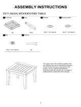
STEP 1
1A Installing The Front Stabilizer: Ensuring that the ARROW STICKER IS POINTING UP so that
the Transport Wheels (93) are parallel to the floor, align the holes of the Front Stabilizer (54) to
the curved bracket at the front end of the Mainframe (59). Insert two Bolts (52) through the Front
Stabilizer (54) and secure with two Curve Washers (55) and two Cap Nuts (56). Using the
Open-Ended Flat Wrench, tighten the Cap Nuts (56) until they are secure.
1B Installing The Rear Stabilizer: Align and attach the Rear Stabilizer (62) to the bracket located
at the bottom of the back end of Mainframe (59) with two Bolts (52). Secure the two Bolts (52)
with two Curve Washers (55) and two Cap Nuts (56). Using the Open-Ended Flat Wrench,
tighten the Cap Nuts (56) until they are secure.
HARDWARE PACK
Multi Hex Tool with Phillips Screwdriver
S8, S13, S14, S15
1 PC
(52) Bolt
4PCS
(55) Curve Washer
4PCS
(56) Cap Nut
4PCS
TOOLS
Open-Ended Flat Wrench

11
ASSEMBLY
STEP 2
2A Greasing The Rotation Rod: Remove the Pre-Assembled two Bolts (5), two Spring Washer
(6), two D Washers (7), two Wave Washer (22) from the Rotation Rod (60). Use the Grease
provided to lubricate a thin, even coat of grease onto the Rotation Rod (60). The Grease will be
used in future steps. Insert the Rotation Rod (60) into the top of the Main Frame (59).
2B Installing The Handrails: Install the Right Handrail (9) onto the right end of the Rotation Rod
(60) with one Wave Washer (22), one D Washer (7), one Spring Washer (6), and one Bolt (5).
Repeat this step for the Left Handrail (77). Be sure the D Washers (7) sit properly along the
Rotation Rod (60). Simultaneously tighten both Bolts (5) with the 6mm Allen Wrench and 6mm
Allen Wrench With Phillips Screwdriver.
2C Installing The Foot Bars: With the bend going downwards install the Right Foot (17) to the
bottom end of the Right Handrail (9) with one Hex Head Bolt (11) and one Nylon Nut (14).
Simultaneously tighten the Hex Head Bolt (11) and Nylon Nut (14) with the Multi-Hex Tool With
Phillips Screwdriver and Open-Ended Flat Wrench. Repeat this process for the Left Foot Bar
(76). Cover the Nylon Nuts (14) and the Hex Head Bolts (11) with Nut Caps (88).
PRE-INSTALLED HARDWARE
(22) Wave Washer
2PCS
(7) D Washer
2PCS
(6) Spring Washer
2PCS
(5) Bolt
2PCS
6mm Allen Wrench with
Phillips Screwdriver
TOOLS
6mm Allen Wrench
Multi-Hex Tool With
Phillips Screwdriver
Open-Ended Flat
Wrench
(11) Hex Head Bolt
2PCS
(14) Nylon Nut
2PCS
HARDWAREWARE PACK
Grease
1PC

12
ASSEMBLY
STEP 3
3A Foot Pedal Support Bracket and Right Crank Bolt Installation: Attach the Foot Pedal
Support Bracket (18) onto the right side of the Right Foot Bar (17) using two Bolts (23), two
Washers (24), and two Nylon Nuts (25). Use the Open-Ended Flat Wrench and 6mm Allen
Wrench to tighten the Foot Pedal Support Bracket (18) to the Right Foot Bar (17).
3B Inserting The Right Crank Bolt Through The Right Foot Bar: Lubricate the Right Crank
Bolt (21) with some of the Grease provided. Insert the Right Crank Bolt (21) and one Wave
Washer (22) through the outside holes of the Right Foot Bar (17).
3C Installing The Right Crank Bolt: Make sure the Right Crank Bolt (21) is perfectly level and
straight as you insert it into the Right Crank (26), through the Right Foot Bar (17) in a
CLOCKWISE direction. Use the 8mm Allen Wrench to tighten the Right Crank Bolt (21). Put one
Spring Washer (27) and one Right Nylon Nut (28) onto the threaded end of the Right Crank Bolt
(21) in a COUNTER-CLOCKWISE direction. Use the Open-Ended Wrench on the Right Nylon
Nut (28) and the 8mm Allen Wrench on the Right Crank Bolt (21) simultaneously to tighten the
Right Nylon Nut (28). Cover the Right Nylon Nut (28) with one Nut Cap (97).
Read the note on next page regarding tightening guidelines. Refer to the illustration
showing the correct installation of the Right Crank Bolt (21). See Figure A on the next page.
Important:
Installing right bolt into right
crank can only be done by
turning right (CLOCKWISE).
R for right bolt
TOOLS
6mm Allen Wrench
Multi-Hex Tool With
Phillips Screwdriver
Open-Ended Flat
Wrench
8mm Allen Wrench

13
Figure A
Note: Figure A shows the correct installation of the
Right Crank Bolt
(21). Keep the bolt perfectly straight when the bolt goes through the
Right Foot Bar (17), and is being screwed into the Right Crank (26).
If the bolt is screwed into the crank at an angle, this may damage the
equipment. Only screw the Right Crank Bolt (21) in a CLOCKWISE
manner.
Make sure that the Right Crank Bolt (21) is used with the Right
Crank (26) only and the left bolt is for the left crank only. If done
incorrectly, the bolts and/or cranks may be damaged or stripped.
(21) Right Crank Bolt
1PC
(23) Bolt
2PCS
(24) Washer
2PCS
(25) Nylon Nut 2PCS
(27) Spring Washer
1PC
(28) Right Nylon Nut
1PC
(97) Nut Cap
1PC
ASSEMBLY
HARDWARE PACK
(22) Wave Washer
1PC
Grease
1PC

14
ASSEMBLY
STEP 4
4A Foot Pedal Support Bracket and Left Crank Bolt Installation: Attach the Foot Pedal
Support Bracket (18) onto the left side of the Left Foot Bar (76) using two Bolts (23), two
Washers (24), and two Nylon Nuts (25). Use the Open-Ended Flat Wrench and 6mm Allen
Wrench to tighten the Foot Pedal Support Bracket (18) to the Left Foot Bar (76).
3B Inserting The Left Crank Bolt Through The Right Foot Bar: Lubricate the Left Crank Bolt
(64) with some of the Grease provided. Insert the Left Crank Bolt (64) and one Wave Washer (22)
through the outside holes of the Left Foot Bar (76).
3C Installing The Left Crank Bolt: Make sure the Left Crank Bolt (64) is perfectly level and
straight as you insert it into the Left Crank (75), through the Left Foot Bar (76) in a
COUNTER-CLOCKWISE direction. Use the 8mm Allen Wrench to tighten the Left Crank Bolt
(64). Put one Spring Washer (27) and one Left Nylon Nut (87) onto the threaded end of the Left
Crank Bolt (64) in a CLOCKWISE direction. Use the Open-Ended Wrench on the Left Nylon Nut
(64) and the 8mm Allen Wrench on the Left Crank Bolt (64) simultaneously to tighten the Left
Nylon Nut (64). Cover the Left Nylon Nut (64) with one Nut Cap (97).
Read the note on next page regarding tightening guidelines. Refer to the illustration
showing the correct installation of the Left Crank Bolt (64). See Figure A on the next page.
L for left bolt
Important:
Installing left bolt into left
crank can only be done
by turning left
(COUNTER-CLOCKWISE).
TOOLS
6mm Allen Wrench
Multi-Hex Tool With
Phillips Screwdriver
Open-Ended Flat
Wrench
8mm Allen Wrench

15
ASSEMBLY
(64) Left Crank Bolt
1PC
(22) Wave Washer
1PC
(23) Bolt
2PCS
(24) Washer
2PCS
Figure A.
Note: Figure A shows the correct installation of the Left Crank Bolt
(64). Keep the bolt perfectly straight when the bolt goes through the
Left
Foot Bar (76), and is being screwed into the Left Crank (75). If the bolt
is screwed into the crank at an angle, this may damage the equipment.
Install the Left Crank Bolt (64) ONLY in the COUNTER-CLOCKWISE
direction.
Make sure that the Left Crank Bolt (64) is used with the Left Crank
(75) only and the left bolt is for the left crank only. If done
incorrectly, the bolts and/or cranks may be damaged or stripped.
(25) Nylon Nut
2PCS
(27) Spring Washer
1PC
(87) Left Nylon Nut
1PC
(97) Nut Cap
1PC
HARDWARE PACK
Grease
1PC

16
ASSEMBLY
STEP 5
5A Right Pedal Installation: Attach the Right Foot Pedal (19R) onto the top of the right side Foot
Pedal Support Bracket (18) located on the Right Foot Bar (17) with two Bolts (20) and two
Nylon Nuts (14). Tighten the Nylon Nuts (14) using the Open-Ended Flat Wrench provided.
5B Left Pedal Installation: Attach the Left Foot Pedal (19L) onto the top of the left side Foot
Pedal Support Bracket (18) located on the Left Foot Bar (76) with two Bolts (20) and two Nylon
Nuts (14). Tighten the Nylon Nuts (14) using the Open-Ended Flat Wrench provided.
TOOLS
Open-Ended Flat Wrench
(20) Bolt
4PCS
(14) Nylon Nut
4PCS
HARDWARE PACK

17
STEP 6
6A Right Handrail Arms Installation: Insert the Right Handrail Arm (2) with the handlebar grip
bent outwards into the Right Lower Handrail (9) and align the holes. Secure the Right Handrail
Arm (2) using two Big Curve Washers (81), two Bolts (47), and two Cap Nuts (80). Tighten the
Cap Nuts (80) and Bolts (47) using the 6mm Allen Wrench and Open-Ended Flat Wrench
simultaneously.
6B Left Handrail Arm Installation: Insert the Left Handrail Arm (90) with the handlebar grip
facing outwards into the Left Lower Handrail (77) and align the holes. Secure the Left Handrail
Arm (90) using two Big Curve Washers (81), two Bolts (47), and two Cap Nuts (80). Tighten the
Cap Nuts (80) and Bolts (47) using the 6mm Allen Wrench and Open-Ended Flat Wrench
simultaneously.
(47) Bolt
4PCS
(81) Big Curve Washer
4PCS
(80) Cap Nut
4PCS
ASSEMBLY
6mm Allen Wrench
Open-Ended Flat Wrench
TOOLS
HARDWARE PACK

18
STEP 7
7A Support Frame Handlebar Installation: As you begin to mount the Hand Pulse Handlebar
Support Frame (41) to the Mainframe (59), insert the Tension Cable (79) through the bottom
opening in the shaft of the Hand Pulse Handlebar Support Frame (41) and pull it out through the
shaft opening located midway up the support frame. See Figure B.
7B Installing The Hand Pulse Handlebar Support Frame: Fully mount the Hand Pulse
Handlebar Support Frame (41) to the Mainframe (59). After being mounted, secure the Hand
Pulse Handlebar Support Frame (41) onto the Mainframe (59) with four Bolts (47), four Spring
Washers (36), and four Washers (24). Use the 6mm Allen Wrench with Phillips Screwdriver to
tighten the Bolts (47) until they are firm and secure.
7C Installing The Sensor Wires To The Mainframe: Connect the Sensor Wire (78) attached to
the Mainframe (59) to the Extension Sensor Wire (10) coming from the bottom end of the Hand
Pulse Handlebar Support Frame (41). Make sure the connectors “click” when connected. See
Figure C.
Multi Hex Tool with Phillips
Screwdriver
TOOLS
6mm Allen Wrench with
Phillips Screwdriver
ASSEMBLY
Figure B
Figure C
(47) Bolt
4PCS
(24) Washer
4PCS
(36) Spring Washer
4PCS
HARDWARE PACK
/