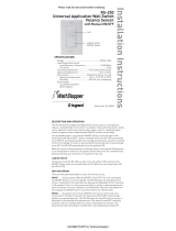
Legrand UT-300-1-U Operating instructions

Type
Operating instructions
Wattstopper
®
Ultrasonic Low Voltage Occupancy Sensor with Manual On Feature,
Light Level and Isolated Relay (version 3)
Détecteur de présence à ultrasons basse tension avec marche en mode manuel,
contrôle du niveau de luminosité et relais isolé (v3)
Sensor de ocupación ultrasónico de bajo voltaje con función de encendido manual,
nivel de luz y relé aislado (v3)
Installation Instructions • Instructions d’Installation • Instrucciones de Instalación
No: 24877 – 1/19 rev. 1
Catalog Numbers • Les Numéros de Catalogue • Números de Catálogo: UT-300-1, UT-300-2, UT-300-3
Country of Origin: Made in China • Pays d’origine: Fabriqué en Chine • País de origen: Hecho en China
Models ending in -U are BAA and TAA compliant (Product produced in the U.S.)
SPECIFICATIONS
Voltage ................................18-28VDC/VAC, half wave rectified AC
Current Consumption ...............................................................25mA
Power Supply ...........................................Wattstopper Power Packs
Operating Temperature .............................32° to 131°F (0° to 55°C)
Time Delay Adjustment ............................30 seconds to 30 minutes
Walk-Through Mode .......... 3 minutes if no activity after 30 sec.
Test Mode .................................... 5 sec. upon DIP switch reset
Ultrasonic Coverage
Model UT-300-1 ..................................................... up to 500 ft
2
Model UT-300-2 ................................................... up to 1000 ft
2
Model UT-300-3 ................................................... up to 2000 ft
2
Sensitivity Adjustment ............. Minimum to Maximum (trimpot)
Frequency .......................................................................40kHz
UL & CUL Listed for use with Wattstopper Power Packs
U.S. Patents: 7,277,012
DESCRIPTION AND OPERATION
The Wattstopper UT-300 sensors turn lighting systems on and off
based on occupancy and ambient light levels. The light level feature
keeps lights from turning on if the ambient light level is sufficient.
The UT-300 can be configured to turn lighting on, and hold it on as
long as it detects cccupancy. After no movement is detected for a user
specified time (5 to 30 minutes) the lights are switched off. A “walk-
through” mode can turn lights off after only 3 minutes, if no activity is
detected after 30 seconds of an occupancy detection.
The UT-300 operates on 24V supplied by Wattstopper Power Packs.
The sensors can operate on 24VDC, 24VAC, or half wave rectified AC.
COVERAGE PATTERN
The UT-300 is available in 3 models. Each model has a different size
coverage pattern. The coverage shown represents walking motion at a
mounting height of 8 to 10 feet. For building spaces with lower levels of
activity or with obstacles and barriers, coverage size may decrease.
0
5'
12'
16'
23'
0
5'
16'23'33' 12'
12'
16'
23'
12' 16' 23' 33'
UT-300/305-3
UT-300/305-2
UT-300/305-1
UT-300/305-3
HALLWAY
APPLICATIO
N
PLACEMENT GUIDELINES
Depending upon obstacles such as furniture or partitions, the area
of coverage may be less or more than the sensing distances shown
in the coverage pattern. This must be considered when planning the
number of sensors and their placement. It is also recommended to
place the sensor 4 to 6 feet away from air supply ducts.
Mount the sensor to the ceiling. The UT-300 is designed for a
ceiling height of about 8-10 feet. Mounting above or below this range
will significantly affect the coverage patterns. As a general rule, each
occupant should be able to clearly view the sensor.
Open Office Area Coverage: To get complete coverage in an open
office area, install multiple sensors so that there is approximately
20% overlap with each adjacent sensor’s ultrasonic coverage area.
2QH87
&RYHUDJH$UHD

8OWUDVRQLF
2YHUODS
2
LVS-1
Load
Rear Housing
Depluggable
Te
rminal
Front Cover
Ceiling
Spring Clips (2)
Blue
Control Out
Black
+24V
Low Voltage
Class 2
Line Voltage
Line
Neutral
Feed Through
Power Pack
Man. Switch
Red
UT-300
Common
For low voltage
momentary switch, set
DIP switch #6 ON
Man.Switch
+24V
Jumper
Back
of
LVS-1
Load #1
Load #2
(Optional)
UT-300
Rear Housing
Depluggable
Te
rminal
Front Cover
Ceiling
Spring Clips (2)
Blue
Control Out
+24V
Common
Low Voltage
Class 2
Line
Voltage
Line
Neutral
Feed Through
Power Pack
Black
Red
#1 #2
Line Voltage
Switches
WIRING DIRECTIONS
Each Wattstopper BZ series power pack can supply power for 5 UT-300
sensors. When using more sensors than this, multiple power packs are
required.
Refer to the wiring diagram for the following procedures:
Connect the low voltage:
RED wire (+24VDC) from power pack to the +24V terminal on the sensor.
BLACK wire (Return) from power pack to Common terminal on the sensor.
BLUE wire from power pack to Control Out terminal on sensor.
To add a manual switch such as the LVS-1 Momentary Toggle Switch, or
RS2-3 Low Voltage Momentary Switch to the above applications–connect:
Wire from one side of switch to +24V terminal on sensor.
Wire from other side of switch to Man Switch terminal on sensor.
Wiring the Isolated Relay: (The Isolated Relay is rated for 1A@30VAC/VDC)
Connect the wires necessary to the application that requires this output:
Relay Common (must be used for proper operation).
N.O. (Normally Open)–Closed when occupancy is detected.
N.C. (Normally Closed)–Open when occupancy is detected.
WARNING: TURN THE POWER OFF AT THE
CIRCUIT BREAKER BEFORE WIRING.
UT-300
Ultrasonic
Occupancy Sensor
U.S.Patents:
5,640,113
Patent Pending
40kHz Ultrasonic
+24VDC/VAC
Connect to WattStopper
Class 2 Power Packs
For Indoor Use Only
03620r2
Relay Com.
N.O.
N.C.
Control Out.
Man. Switch
+24V
Common
LISTED
88T9
Appliance
Control
V3
Wiring
terminals
CONNECTING WIRES
Care should be taken to separate high voltage power from low voltage (Class 2) control wiring.
All connections to sensor are low voltage, Class 2.
Standard wiring with local off switch Manual-On wiring with low voltage momentary switch
MOUNTING THE SENSOR
Directly to Ceiling
1. Attach the plastic spring clips to the edge of the sensor in the slots provided.
2. Cut a 3.5” to 4” round hole in the acoustic ceiling tile at the mounting location. A 3.5”
hole is recommended for a secure fit.
3. Pull the low voltage wire from the power pack to the sensor through the hole.
4. Connect the low voltage wires to the appropriate terminals on the sensor.
5. Push the sensor up through the hole until the Spring Clips hold the sensor securely in
place.
6. Snap the front cover onto the sensor.
5HDU
KRXVLQJ
'HSOXJJDEOHWHUPLQDO
)URQW
FRYHU
&HLOLQJ
6SULQJFOLSV
Ceiling Mount
3
Using an Octagonal J-Box
1. Pull the low voltage wires from the power pack into the J-Box through the conduit
knockout.
2. Connect the low voltage wires to the appropriate terminals on the sensor.
3. Loosen the appliance mounting screws attached to the J-Box
4. Align the sensor in the J-Box so that the mounting screws on the box match the key
holes on the sensor’s rear housing.
5. Push the sensor up into the J -Box and twist it so that the mounting screws are seated
in the keyhole slots.
6. Tighten the two screws to secure the sensor to the J-Box.
7. Snap the front cover onto the sensor.
Rear
Housing
Depluggable
Terminal
4" Octagonal J-Box
(at least 1.5" deep)
Front
Cover
Ceiling
Screws
J-Box Mount
SENSOR ADJUSTMENT
NOTE: This unit is pre-set for basic operation as described in this guide. Adjustment is optional.
The sensors are factory preset to allow for quick installation in most applications.
Verification of proper wiring or coverage, or customizing the sensor’s settings can
be done using the following procedures. To make adjustments, open the Front
Cover with a small screwdriver.
Before making adjustments, make sure the office furniture is installed, lighting
circuits are turned on, and the HVAC systems are in the overridden/ on position.
VAV systems should be set to their highest airflow. Set the Time Delay to the
desired settings. See DIP Switch Setting.
To Test Occupancy Sensors
1. Ensure the Time Delay is set for Test Mode* using the “Test Mode/20
minutes” setting. (DIP Switches 1, 2, & 3 are OFF).
2. Ensure that the Ultrasonic Sensitivity trimpot is set to about 70%, clockwise.
3. Remain still. The LED should not flash. The lights should turn off after 5 seconds. (If not, see Troubleshooting.)
4. Move about the coverage area. The lights should come ON. Adjust the Ultrasonic Sensitivity as necessary to provide the desired
coverage (Green LED indicates activation from the ultrasonic sensor).
When testing and adjustment are complete, reset DIP Switches to the desired settings, and replace the cover on the sensor.
*Test Mode is a temporary state that starts when you first set the sensor’s DIP Switches for the “Test Mode/20 minutes” (Switches 1, 2,
3 OFF). If you need to invoke the Test Mode and the DIP Switches are already set for Test Mode/20 minutes, toggle DIP Switch 1 ON,
then back to the OFF position. This provides a 10 minute test period. During the test period, the Time Delay is only 5 seconds.
LIGHT LEVEL FEATURE
The Light Level feature holds lights off upon initial occupancy if adequate ambient light exists. It will not turn the lights OFF if they are
ON. The default setting is for maximum, meaning that even the brightest ambient light will not hold the lights OFF.
Notes on Functionality
Avoid mounting the sensor close to lighting fixtures.
Adjust during daylight hours when ambient light in the area is at desired level.
Light Level cannot be enabled while Test Mode is active. Either wait for Test Mode to expire or select any of the other Time Delay
settings before enabling the Light Level feature.
PIR occupancy indicator LED may still respond when lights are being held OFF. LED will also flash periodically to indicate the
sensor has Light Level enabled.
Light Level settings are only saved in the event of a power loss. Disabling Light Level and then reenabling it will not return it to
previous settings.
If Test Mode is enabled after Light Level has been set, Light Level functionality will cease to function throughout the duration of Test
Mode. When Test Mode period expires, the Light Level functionality will resume, even if the DIP Switches remain set to Test Mode.
Setting Light Level
1. Make sure Test Mode is not active.
2. Toggle the state of the sensor, by briefly pressing the Light Level button, to include or exclude the lighting load from the light level
calibration. Open the Front Cover and locate the Light Level pusbbutton. See Sensor Adjustment.
3. Press and hold the Light Level button for 2 or more seconds, or until the detection LED turns ON. Do not exceed 5 seconds.* The
sensor enters setup mode, as indicated by the rapidly flashing LED. The LED will flash throughout the setup process. Occupancy
indication from the LED is disabled during setup.
4. Move away from the sensor to avoid interference with light level detection. The sensor measures the light level for a 10 second
period, then averages the readings and automatically sets the level that will be used as the new setting. The sensor will hold lights
off when the ambient light exceeds this setting.
5. When the LED stops flashing, replace the Front Cover.
*Disabling Light Level
Pressing the pushbutton for 5 seconds or more resets the light to default (maximum).
Press and hold the Light Level button for 5 seconds or until the detection LED turns ON and then OFF. The LED flashes rapidly for
10 seconds after the setting has changed.
.H\KROHVORWV
IRUPRXQWLQJWR
RFWDJRQDOER[
'RXEOHJDQJ
PXGULQJ
PRXQWLQJKROHV
',3VZLWFKHV
21
(&(
8OWUDVRQLF
WUDQVGXFHU
FRQHV
8OWUDVRQLF
DFWLYLW\
/('*UHHQ
/LJKWOHYHO
SXVKEXWWRQ
8OWUDVRQLF
VHQVLWLYLW\WULPSRW
4
DIP SWITCH SETTING
Time Delay: Switches 1, 2, 3
The sensor will hold the lights ON as long as occupancy is detected. The time delay countdown starts when no
motion is detected. After no motion is detected for the length of the time delay, the sensor will turn the lights OFF.
Walk-Through Switch 4
Walk-Through mode turns the lights OFF three minutes after the area is initially occupied, if no motion is
detected after the first
30 seconds. If motion continues beyond the first 30 seconds, the selected time delay applies.
Service: Switch 5
To override all sensor functions, set DIP Switch 5 to the ON position. The green LED will come on and stay on
for the duration of the override. This bypasses the occupancy control functions of the sensor, but still allows
the lights to be manually controlled with a light switch, if one is installed.
On Mode: Switch 6
The Manual ON function is facilitated by installing a momentary switch such as a Wattstopper LVS-1
Momentary Toggle Switch, or RS2-3 Low Voltage Momentary Switch. This switch connects to the sensor’s
Manual (Man.) Switch and +24V terminals as shown in the wiring diagram. Each time the switch is pressed,
the load changes state. The sensor’s operation as related to the manually operated switch is determined by
the setting for DIP Switch 6.
Manual On: In this mode, the switch is required to turn ON the load. The sensor is then used to keep the load
on, based on occupant activity. After the time delay ends, if there is no movement detected within the
30 second re-trigger period the manual switch must be used to turn ON the load.
Automatic On: This mode uses occupancy as well as switch activation to turn the load ON. A manual switch
provides the following additional functionality:
1. The load can be turned ON by manual switch activation and it stays on as long as occupancy is detected. The sensor time delay
operates as programmed. When the load turns OFF due to lack of occupancy detection, the load can be turned ON again by
occupancy detection or switch activation.
2. Activating the manual switch while the load is ON turns the load OFF.
When the load is turned OFF manually, as long as the sensor continues to detect occupancy the load stays OFF. For the
selected time delay, the lights stay OFF and the sensor reverts to the automatic-on mode.
When the load is turned OFF manually, pressing the switch again turns the load ON and the sensor reverts to the automatic-on mode.
Once the sensor returns to automatic-on mode, either the switch or occupancy detection can turn the load ON.
OVERLOAD PROTECTION
The occupancy sensor has a built in overload protection function that will automatically turn OFF the control output when the load
current exceeds 200mA. The sensor LED will then blink rapidly (~ 10Hz) to provide a visual indication of an overload condition. When
the load current is corrected or returns to normal, the control output will turn back ON.
TROUBLESHOOTING
For any unexpected operation:
1. Check DIP switch settings.
2. Make sure the switches are set according to the defined settings in the DIP Switch Setting chart.
Lights do not turn on with occupancy, and the LED does not ash:
1. Check that the circuit breaker has been turned back on.
2. The Ultrasonic Sensitivity setting may need to be increased.
3. Turn clockwise as needed.
4. Check all sensor and power pack wire connections.
5. Check for 24V input to the sensor.
If 24V is present, replace the sensor.
If 24V is not present, check that high voltage is present to power pack.
If it is, replace power pack.
Lights do not turn off automatically:
1. The sensor may be experiencing activations from outside the controlled area or from some type of interference (see “Unwanted
Sensor Activations” below).
2. Check all sensor wire connections.
3. Disconnect power pack’s blue wire:
If the lights do not turn off, replace power pack. Reconnect blue wire.
If the lights turn off, the problem may be in the sensor–to check:
Reconnect the blue wire.
Turn sensitivity and time delay to minimum and allow the sensor to time out.
If the lights turn off, the sensor is working properly (see number 1, above, and “Sensor Adjustment” for readjustment of sensor).
4. Set sensitivity and time delay to minimum and allow the sensor to time out.
If the lights turn off, the sensor is working properly (see number 1, above, and “Sensor Adjustment” for readjustment of sensor).
Switch#
5 minutes
10 minutes
15 minutes
20 minutes
25 minutes
30 minutes
30 seconds
123
Time Delay
Test Mode/20 min
5
Auto On
Manual On
6
Normal
Service
Service
= ON
= OFF
= Factory Setting
4
Disabled
Enabled
Walk-Through
On Mode
5
Unwanted Sensor Activations (LED ashes):
Possible causes
1. The ultrasonic sensitivity may be too high causing detection outside of desired coverage area.
2. Sensor located too close to HVAC or VAV vents with heavy air flow.
3. If LED is flashing rapidly (~10Hz), an overload condition exists. When this is corrected, the sensor will return to normal operation.
Possible solutions
1. Reduce the ultrasonic sensitivity (counterclockwise) as needed (see “Sensor Adjustment”).
2. Relocate the sensor.
3. Check the blue wire connection. If necessary, replace the power pack.
ORDERING INFORMATION
Catalog# Description
UT-300-1 Ultrasonic Occupancy Sensor, up to 300 sq ft coverage, Low Voltage w/Isolated Relay and Manual On Feature
UT-300-2 Ultrasonic Occupancy Sensor, up to 1000 sq ft coverage, Low Voltage w/Isolated Relay and Manual On Feature
UT-300-3 Ultrasonic Occupancy Sensor, up to 2000 sq ft coverage, Low Voltage w/Isolated Relay and Manual On Feature
BZ-50 Power Pack: 120/277VAC, 50/60Hz, 20A ballast or incandescent
BZ-150 Power Pack: 120/277VAC, 50/60Hz, 20A ballast or incandescent, with Hold-On and Hold-Off capability
BZ-200 Power Pack: 120/277VAC, 50/60 Hz, 20A Ballast/ELV/MLV/Incandescent/LED, 16A, E-Ballast/CFL/Plug Load
BZ-250 Power Pack: 120/277VAC, 50/60 Hz, 20A, Ballast/ELV/MLV/Incandescent/LED, 16A E-Ballast/CFL/Plug Load,
with Hold-On/Hold-Off capability
BZ-250-347 Power Pack: 120/347VAC, 50/60 Hz, 16A Ballast/ELV/MLV/Incandescent/LED/ E-Ballast/CFL, 15A Plug Load,
with Hold-On/Hold-Off capability
Sensors are White. BZ series power packs supply power for up to 5 UT-300 sensors.
INSTRUCTIONS EN FRANÇAIS
CARACTÉRISTIQUES TECHNIQUES
Tension .................18-28 VCC/VCA, courant alternatif redressé mono alternance
Consommation actuelle .................................................................................25mA
Alimentation électrique .......................................Blocs d'alimentation Wattstopper
Température de fonctionnement ..................................0 ° à 55 °C (32 ° à 131 °F)
Réglage de la temporisation.........................................30 secondes à 30 minutes
Mode passage .................................. 3 minutes si aucune activité après 30 s
Mode test .......................................5 s après activation de l'interrupteur DIP
Couverture ultrasonique
Modèle UT-300-1 ....................................................... jusqu'à 47 m2 (500 pi
2)
Modèle UT-300-2 .................................................... jusqu'à 93 m2 (1 000 pi
2)
Modèle UT-300-3 .................................................. jusqu'à 186 m2 (2 000 pi
2)
Réglage de la sensibilité .................... Minimum à maximum (potentiomètre)
Fréquence ............................................................................................40kHz
UL & CUL listés pour une utilisation avec les blocs d'alimentation Wattstopper
Brevets américains : 7 277 012
DESCRIPTION ET FONCTIONNEMENT
Les détecteurs Wattstopper UT-300 allument et éteignent
les systèmes d'éclairage selon la détection de présence.
Le détecteur UT-300 peut être configuré pour allumer
l'éclairage et le maintenir ainsi tant qu'il détecte une
présence. Si aucun mouvement n'est détecté pendant
une durée spécifiée par l'utilisateur (5 à 30 minutes), les
lumières sont éteintes. Le mode « passage » permet
d'éteindre les lumières au bout de 3 minutes seulement
si aucun mouvement n'est détecté 30 secondes après la
détection d'une présence.
Le modèle UT-300 fonctionne avec un courant de 24V
fourni par les blocs d'alimentation Wattstopper. Les
détecteurs peuvent fonctionner avec un courant 24VCC,
24VCC ou un courant alternatif redressé mono alternance.
PORTÉE
Le détecteur UT-300 est disponible en 3 modèles. Chaque
modèle possède un schéma de portée de taille différente.
La portée indiquée dans le schéma représente un
mouvement de marche à une hauteur de 2,4 à 3 mètres
(8 à 10 pieds) Pour les bâtiments avec une activité plus
faible ou avec des obstacles et barrières, la zone de
portée risque de diminuer.
0
1.5m
3.7m
4.9m
7m
0
1.5m
4.9m7m10.1m 3.7m
3.7m
4.9m
7m
3.7m 4.9m 7m 10.1m
UT-300/305-3
UT-300/305-2
UT-300/305-1
UT-300/305-3
APPLICA
TION
EN COULOIR
  • Page 1 1
  • Page 2 2
  • Page 3 3
  • Page 4 4
  • Page 5 5
  • Page 6 6
  • Page 7 7
  • Page 8 8
  • Page 9 9
  • Page 10 10
  • Page 11 11
  • Page 12 12
  • Page 13 13
  • Page 14 14
  • Page 15 15
  • Page 16 16

Legrand UT-300-1-U Operating instructions

Type
Operating instructions

Ask a question and I''ll find the answer in the document

Finding information in a document is now easier with AI